For effective business use of Gazelle cars, all engine systems must work properly. One of the key elements that ensures efficiency and maximum engine performance is the mass air flow sensor. This device is known to motorists under the abbreviation DMRV, or in the English version MAF. A malfunction or incorrect operation of this sensor will in any case lead to additional costs: increased fuel consumption or the purchase of a new mass air flow sensor for your Gazelle car. Therefore, the driver must ensure conditions under which the flow meter will last as long as possible.
Operating principle of the air flow sensor
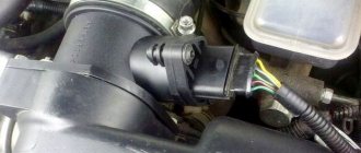
The device is installed between the air filter and the throttle valve. It determines the amount of air flowing into the engine intake manifold.
There are two design solutions:
- Mechanical (vane type) works using a plate of a certain size connected to a variable resistor. Under air pressure, the plate deflects, the resistance changes, and the electronic engine control unit receives information for the correct formation of the fuel mixture.
- The electronic sensor can be wire (platinum is used) or film. It is these options, depending on the environmental class of the car, that are used on Gazelle Business. Let's take a closer look at the scheme of its operation.
The device is an air duct, the diameter of which corresponds to the air line of the vehicle’s intake system. Inside there are a number of electronic components.
The operating principle is “thermo-anemometric”. What does this mean in practice?
The main element of the mass air flow sensor is an element whose resistance depends on temperature. Its value is constantly (in real time) compared with a reference constant resistor, which operates under the same conditions (located in close proximity). Air passes through the temperature-sensitive element, and depending on the intensity of the flow, cooling occurs. The resistance changes, the element has to be heated with electric current to match the reference resistor. That is, we get a linear dependence of current and voltage on the volume of air passing through the mass air flow sensor. It is this value that is analyzed by the sensor control module. The information is transmitted to the ECU, as a result of which the electronic brain of the engine selects the optimal composition of the fuel-air mixture.
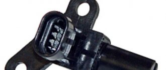
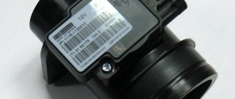
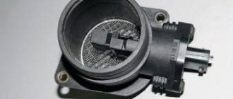
The operating algorithm seems complicated at first glance, but in fact this is the most reliable and inexpensive implementation of an air flow sensor. The main heat-sensitive element can be wire (platinum-iridium alloy) or film. The second option is more accurate and is used on Gazelle cars with a higher environmental class Euro 3. For example, Siemens mass air flow sensor (in the illustration).
Information: when using simpler (filament) flow sensors, manual adjustment of the CO level in the exhaust gases is possible. More modern (film) mass air flow sensors do not require such adjustment; exhaust toxicity is maintained at a safe level automatically.
Possible controller malfunctions
The following errors may indicate device malfunctions:
- P0131, P0132. These errors indicate that the signal level from the oxygen sensor is too low or too high.
- P0134. The control unit did not detect the activity of the lambda probe.
- P0135. This error may indicate an open circuit connecting the sensor, as well as a possible short to power or ground.
- P0133. Controller response is too slow.
- P0137, P0138. Very low or high signal from the second lambda probe.
- P0141. The malfunction also concerns the second oxygen sensor, in this case we are talking about an open circuit or short circuit (the author of the video is the Lty D channel).
Where to buy car accessories
Spare parts and other products for the car are easily available for purchase at auto stores in your city. But there is another option that has recently received significant improvements. You no longer need to wait a long time for a parcel from China: the AliExpress online store now offers the opportunity to ship from transshipment warehouses located in various countries. For example, when ordering, you can specify the “Delivery from the Russian Federation” option.
Follow the links and choose:
| DVR, Dual, 1080P, 4G, Android 8.1, 10-inch | Charger with two USB ports, 5 V | AUTOOL X95 car compass, horizontal inclinometer, speedometer |
| 12V car heater | HD night vision camera with 360 degree viewing angle | Karadar G820STR radar detector with GPS |
Sequence of actions when calling
- Before you test the circuit with a multimeter, you need to turn the handle of the device to the desired position.
- Install the ends (measuring leads) into the appropriate sockets. The black wire goes into the socket marked COM (sometimes it can be marked with “*” or a ground sign), and the red wire goes into the socket where the Ω sign is indicated (sometimes it can be marked with an R sign). It is worth noting that the Ω sign can be applied either separately or in combination with the designations of other units of measurement (V, mA). This is the correct position of the test leads, which will allow you to maintain polarity when making further measurements. Although if only the integrity of the wires is checked, their relative position will not affect the result obtained.
- Turn on the device. A separate button may be provided for this, or activation may occur automatically when the knob is turned to the desired position when selecting measurement limits or operating modes.
- Connect the measuring ends to each other. If a signal sounds, it means that the device is operational and ready for use.
- Take the cable or wire being tested (its ends must first be stripped of insulation, stripped to a metallic shine, and dirt and oxides removed from the surface). Touch the test leads to the exposed areas of the conductor.
- In case of continuity, a signal will sound, and the device readings will either be 0 or indicate the resistance value. If the display shows 1 and there is no beep, the tested conductor is broken.
https://youtube.com/watch?v=EIyKzTBhyBA
https://youtube.com/watch?v=EIyKzTBhyBA
What can break in the air flow sensor
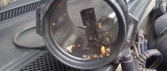
- Trivial clogging of the flow meter. During severe operation in city mode or on dusty country roads, the air filter may not cope and allow the smallest particles to enter the channel. The sensors can be cleaned with compressed air or a special aerosol product if the problem is not severe.
- Ingress of return gases from the intake manifold (incorrect operation of the USR) onto the sensitive elements. The problem is typical for cars with a high Euro environmental class.
- Physical damage to the temperature sensitive element. It can deteriorate from normal wear and tear or from foreign objects (including oil or moisture). The element itself cannot be repaired (at least the labor costs are higher than the actual cost of a new AFMV). Therefore, it would be wiser to simply replace the entire flow meter.
- Mechanical damage to the body of the measuring channel (dents, cracks). Plastic can be restored if the internal geometry is not damaged. A similar “fault” is that the housing does not fit tightly to the air duct flange or throttle body.
- Destruction of the contact group (connector) or oxidation of contacts. The air flow sensor is installed in a place exposed to negative environmental influences (humidity, temperature changes, etc.)
Broken contacts can be determined visually, or by ringing using a tester. If the contact group on the wiring harness connector is broken, it can be replaced. The contacts in the mass flow sensor housing are more difficult to restore. Oxidation can be eliminated by simple cleaning with a stiff brush. Then you need to apply a special lubricant to the contacts. - Broken power or signal wire. Even a completely serviceable mass air flow sensor will not work if there is no contact or a damaged cable. The malfunction can be easily fixed using a soldering iron.
Tip: Do not twist broken wires together. In conditions of the engine compartment, such a joint will not last long.
Checking the regulator for functionality
Diagnostics of the oxygen sensor is carried out as follows:
- First, the device must be inspected. If visual diagnostics made it possible to identify defects in the device, then most likely it was the damage that caused its failure. If so, then the device changes.
- If the error shows an open circuit, then you need to try to find a break in the wiring or damage to the electrical circuit.
- Disconnect the device from the power connector, perform a visual check of both plugs - the sensor itself and the connection circuit. If there are traces of rust or deposits or oxidation on the connectors, you can try to clean them. If the marks are strong and cannot be cleaned off, or if you damaged the contacts while cleaning, they should be replaced.
- If these steps did not help you identify problems, then you will need a tester to proceed further. Get your multimeter ready, reconnect the sensor, start the engine and warm it up to operating temperature, then turn it off.
- Then the oxygen controller will need to be disconnected from the connector again, after which it will connect to the tester.
- The car engine starts again, now you need to sit in the driver's seat and press the gas to increase the speed. The revolutions should be kept around 2500 per minute.
- Look at the multimeter screen - if the value is close to 0.9 W, this indicates that the lambda probe is in good condition and does not require replacement. If the readings do not rise above 0.8 W, this indicates the need to replace the regulator. Then all you have to do is dismantle it and replace it with a new one.
Pinout and connection of the Gazelle mass air flow sensor
To find out where the contact is missing, or to measure the supply and signal voltage, a diagram is needed. Consider the option for a film mass air flow sensor from Siemens.
A slight digression from the topic
The illustration shows how tightly the mass air flow sensor is integrated into the control system of the electronic engine unit. The slightest failure in data exchange will instantly disrupt the formation of the fuel-air mixture. The result is a loss of power and increased fuel consumption.
It is important to know: a breakdown or even complete removal of the mass air flow sensor from the ECU system will not lead to the car stopping. However, prolonged operation without a sensor has a detrimental effect on engine life, not to mention ongoing financial losses.
Briefly about the renovation
As a rule, MAF sensors that have become unusable cannot be repaired, except in cases where they require washing and cleaning.
In some cases, it is possible to repair the volumetric air flow sensor board, but this process will not prolong the life of the device for long. As for the boards in film sensors, without special equipment (for example, a programmer for a microcontroller), as well as skills and experience, it is pointless to try to restore them.
Internal combustion engines in cars operate by supplying not only gasoline alone, but a combustible fuel mixture into the combustion chamber. The concept of fuel mixture refers to a certain amount of gasoline and air. If on the predecessors of the UAZ Patriot SUVs, air supply adjustment was the responsibility of the driver, now a special sensor known as the mass air flow sensor is responsible for this. The mass air flow sensor determines the required amount of air that is required to be supplied to the cylinders along with fuel. Thus, a malfunction of this device leads to improper operation of the engine, so you need to know how to troubleshoot the product, as well as troubleshoot and replace the product on a UAZ Patriot SUV.
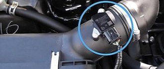
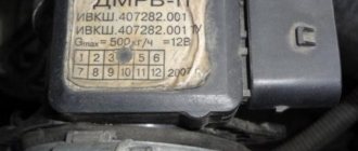
The mass air flow sensor on the UAZ Patriot SUV is a plastic pipe, the functioning of which is carried out by changing the value of internal resistance. Power is supplied to the sensor via wires. The product is located under the hood of the car after the air intake filter on the intake manifold between the air filter and the exhaust pipe. The photo below shows the location of the product.
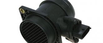
UAZ Patriot SUVs are equipped with two types of mass air flow sensors type HFM5-4.7 with number 0280218037 from Bosch or mass air flow sensor from Siemens type 20.3855. The main purpose of the sensor is to determine the volume of air that passes through it. But, in addition, the mass air flow sensor allows you to determine the temperature of the incoming air, as a result of which the controller calculates the exact volume of air required to create the air-fuel mixture. The temperature of the incoming air is controlled by means of a sensor installed in
thermister. In the event of a product failure, the controller receiving the signals takes a fixed air temperature value of 33 degrees. The cost of the product is about 3000-5000 rubles, which depends on the manufacturer of the product. Let's look at the main types of malfunctions of the mass flow sensor on the UAZ Patriot SUV.
Types of faults
A faulty mass air flow sensor leads to disappointing consequences, so it is very important to ensure its performance. Malfunctions of these devices may manifest themselves in the following ways:. What does the sensor consist of?
What does the sensor consist of?
- The first factor indicating a malfunction of any element on the car is the illumination of the Check Engine indicator.
- At the same time, an increase in fuel consumption is observed.
- The UAZ Patriot car cannot be started after the engine has warmed up.
- While the car is moving, the driver can feel the UAZ Patriot “stupid”.
If the above symptoms are detected, you should immediately proceed to correct the breakdown. To do this, the first step is to remove the mass air flow sensor and inspect it. Let's look at what the process of removing the mass air flow sensor on a UAZ Patriot Euro-3 SUV is like.
Removal and replacement
The process of removing the product is not difficult and does not take more than 10-15 minutes. All you need to remove the sensor is a 10mm wrench and a Phillips screwdriver. The first step is to de-energize the car by removing the negative terminal from the battery. After this, we proceed to the direct process of removing the sensor from the UAZ Patriot SUV:
Disconnect the hoses from the sensor
- From the bottom of the device, you need to press the plastic clamp of the terminal block and remove it from the sensor.
- Next, loosen the clamps using a Phillips screwdriver.
- Now you can remove the rubber pipes from the product and remove the released element.
This is actually the mass air flow sensor of the UAZ Patriot SUV Euro-3 and Euro-4. After removal, you can check its serviceability. How the mass air flow sensor is checked is discussed below. If this device becomes unusable, it must be replaced with a new part. The process of installing the mass air flow sensor on a UAZ Patriot SUV is performed in the reverse order of removal.
How to check the serviceability of the mass air flow sensor
First of all, you need to regularly carry out computer diagnostics of your car, even in a garage, using basic car scanners. Any version of the Gazelle car is equipped with an OBD-II port, with which you can obtain detailed information about the operation of the engine’s electronic systems.
The initial parameters of the air flow sensor (we first select the model and type of engine on your car) are programmed into the diagnostic program. So a deviation from the norm will be recorded, and advanced programs will also suggest the probable cause of the breakdown.
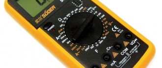
However, there is a more primitive method that you can use if you don’t have a diagnostic scanner at hand. Every car enthusiast has a digital multimeter in their garage. The main thing is that its error is low: the voltage readings at the information contact of the mass air flow sensor vary within hundredths of a volt, and it is precisely this minimum range of values that the ECU is designed for.
The illustration shows the pinout of a sensor from Siemens, or its Russian analogues Avtel and Elkar.
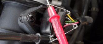
- First of all, we check the integrity of the wiring harness and cable contact group. To do this (having first disconnected the negative terminal of the battery), disconnect the connector and connect the battery back. Turn on the ignition without turning the starter. There should be 12 volts on pin #2. Not 13.5, as on the battery, but precisely 12, after the voltage regulator. At pin No. 4 the sensor is supplied with 5 volts.
- Then we connect the connector back (remembering to temporarily disconnect the battery ground). We check the most important sensor signal: thermistor compensation voltage. With the ignition on, this value should be in the range of 0.99 - 1.02 volts. 1.03 - 1.05 volts are allowed, but such a mass air flow sensor will not last long. Any other value, even with a tolerance of 0.01 volts from the nominal value, indicates a breakdown.
What you need to know about the device to connect wires
dialing mode
If you plan to test the wiring in your apartment, you need to know several fundamentally important facts about multimeters. First of all, it is worth noting that you can check the wire with the simplest device. An inexpensive Chinese model with minimal capabilities is quite suitable.
But at the same time, it is most convenient to use a device that has the dialing function itself. In order to set the device handle to the appropriate position, you need to turn it in the direction of the diode icon (as an option, an image of a sound wave can additionally be applied). This means that when checking the integrity of the wire, a sound signal will sound when the contacts are closed.
But the presence of sound is completely optional for testing wires with a multimeter. The fact that the circuit is broken will be indicated by a unit on the display, indicating that the resistance level between the probes is higher than the measurement limit. If there is no damage in the area under study, the resistance value will be displayed on the screen, which ideally should tend to zero (subject to operation in short-distance household networks).
Tags: zmz 406
Comments 26
My consumption at XX is generally 0.9-1) Thanks DBP) But in general, the normal consumption for the mass flow sensor is 1.2. If it is too high, it means that the injectors are not topped up, the injectors open more strongly, and from here the instantaneous flow rate is taken based on the opening time. It's either the injectors or the fuel pump. In general, it would be flashed for 580 at least. In terms of temperature - well, it’s not at work. It should be approximately above 80 for various corrections to cease to apply. For 406, the normal temperature is 87 where RCOD RCOK - suspiciously the same - set it according to the gas analyzer. Leave the correction at -2 if you drive at a good 92m. I drove the 95 at -5
I just measured these parameters at 80. and so the fan on 87 turns on. 580 how to flash? Are there any pitfalls? MAF Siemens 20.3855. you need to look at the markings exactly. RCOD RCOK approximately what should they be? Are they exposed to a hot internal combustion engine?
Only the gas valve at operating temperature will tell you approximately; if it is not there, I recommend setting it to zero.
It's not difficult to flash, do you have an adapter for diagnostics? I can upload the firmware slightly corrected
I know how to flash it, and I corrected the old firmware in the fuel supply mode at start-up. otherwise it flooded from -5 degrees and below.
Then there is no reason to worry at all - feel free to upgrade to 580
My consumption at XX is generally 0.9-1) Thanks DBP) But in general, the normal consumption for the mass flow sensor is 1.2. If it is too high, it means that the injectors are not topped up, the injectors open more strongly, and from here the instantaneous flow rate is taken based on the opening time. It's either the injectors or the fuel pump. In general, it would be flashed for 580 at least. In terms of temperature - well, it’s not at work. It should be approximately above 80 for various corrections to cease to apply. For 406, the normal temperature is 87 where RCOD RCOK - suspiciously the same - set it according to the gas analyzer. Leave the correction at -2 if you drive at a good 92m. I drove the 95 at -5
hi, I accidentally came across your comment. Similar shit is happening to me, but I didn’t find any answers, and your comment seems to be close to me... I have 1.4-1.5 on the xx, but sometimes with the tank filled more than half you can see 1.2-1.3 in traffic jams. There is no traction... the engine you accelerate... you get this feeling when you are driving at lower speeds. And there is no carbon deposits on the spark plugs; on the contrary, they are slightly white. Like when depleted. In the summer I changed the throttle, and the spark plugs eliminated the leaks in the engine for a while so I didn’t feel the weight of the car. Like a feather. And then somehow it started to work again... now I’m thinking about the injectors to clean them individually at the stand. Do you think this will increase the filling of the cylinders or should I look elsewhere? I was in diagnostics, the pump presses normally, the phases are not knocked down, the injectors are not clogged. but for some reason on their computer the hourly consumption shows 1.2 and my onboard one is 1.4-1.5
source
Rules for safe calling using a multimeter
testing the network cable with a multimeter
Working with electricity does not allow for unprofessionalism, so a certain list of rules has been developed that make it possible to make it as accurate, fast and safe as possible.
When making calls, it is most convenient to use special tips at the ends of the measuring wires, which are more commonly known as “crocodiles”. They will make the contact stable and free your hands when taking measurements. When testing, the circuit being tested must always be de-energized (even low-current batteries must be removed). If there are capacitors in the circuit, they must be discharged by short-circuiting
Otherwise, the device will simply burn out during work. Before checking the integrity of a long length of conductor when taking measurements, it is important not to touch its bare ends with your hands. This is due to the fact that the resulting readings may be incorrect.
When testing a multi-core cable, it is necessary to separate and strip all existing cores from both ends. After this, you need to check the circuit for the presence of short circuits in it: to do this, a “crocodile” is attached to each core in turn, and all the remaining ones are touched with the other measuring end in all possible combinations.
Check to see if there is a short circuit between the cable cores. If the indicator shows “1” and there is no sound signal, then everything is in order, otherwise there is a short circuit.
In this case, a sound signal will indicate the presence of a short circuit between the tested conductors
This may not be of practical importance for small cross-section multi-core cables operating in low-current networks, but when working with high voltages it is fundamentally important
We call the cable cores. There is a sound signal - everything is fine, otherwise the core is damaged.
To determine the integrity of the cores, the same operation is performed, only at one end of the cable all stripped cores are twisted together
When searching for a break, it is important to consider that the absence of a sound signal at either end will indicate a violation of the integrity of the conductor