The diode bridge of the generator on VAZ 2110 cars very often fails. Its malfunction can be indicated by rapid and strong heating of the car generator.
Today we will talk about how to check a diode bridge with your own hands, while saving money and time on a trip to specialists at a car service center. I once wrote about why the generator heats up on VAZ cars , this time we will talk specifically about the diode bridge, or more precisely about how to check and replace it at home.
It’s probably not worth talking about the role of a generator in a car; everyone knows that this is a very important part, without which one cannot imagine an engine. The service life of the battery, which receives charging from the generator, largely depends on the performance of the generator.
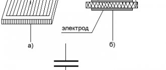
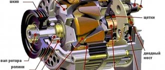
A diode bridge consists of four or six diodes that convert alternating current into direct current according to the principle of a bipolar rectification method. The rectifier diodes of the generator play the role of a gateway that allows current to flow in only one direction, preventing current from the vehicle’s on-board electrical network from passing to the stator windings. The diodes are located on the generator body and tend to burn out, there are several reasons for this.
How to test a car alternator with a multimeter
Stable and correct operation of the car’s electronics largely depends on the serviceability of the generator. It provides power to all devices and also helps start the engine. In this regard, it is important to monitor its serviceability, and if necessary, know how to check a car generator with a multimeter.
This element is directly connected to the battery, which also often causes problems. And if it is necessary to connect new devices and various devices to the standard on-board network, you should check the serviceability of the generator, since it is the source of the standard current. In other words, this is one of those parts that needs to be checked regularly.
Beginning of work
To start checking, no special preparations are required. You just need to prepare the multimeter itself. It is also advisable to check the generator - inspect the generator stator, diode bridge, voltage regulator, etc. This makes it possible to identify faults at an early stage. In addition, an external inspection of other elements of the vehicle's electrical circuit should be carried out. No further work may be required.
So, the verification includes several stages:
- Inspection of the relay regulator.
- Checking the diode bridge.
- Checking the stator.
- Checking the rotor.
Relay regulator
The relay regulator maintains the optimal voltage value in the standard electrical circuit. In fact, it is precisely this that prevents the voltage from increasing to critical values. To carry out the test, start the engine, connect the multimeter and set the “voltage measurement” value.
After this, it is necessary to measure the power supply of the on-board network directly at the battery terminals or at the contacts of the generator itself. The values should be between 14–14.2 V.
Then you need to press the accelerator and take the measurement again.
Note! The readings should not change by more than 0.5 V. Otherwise, this will indicate incorrect operation.
What malfunctions can occur in the generator?
What could be the problem with the generator when, when you turn on the ignition, the light flashes or does not turn on at all and the control devices do not function? You should check to see if the fuse located in the mounting block is ok. If there is a break in the power supply, the following may occur:
- the “O” wire with the wires from the mounting block to the devices is broken;
- there was a breakdown of the “GP” wire with the wires from the ignition switch to this unit.
If the battery is discharged, the generator voltage will not give the desired figure.
And the reason may lie in the fact that the control lamp has burned out, or perhaps the socket contacts are not pressed sufficiently against the printed circuit board. In this case, the lamp or faulty contacts are replaced.
You should look to see if there is an open circuit in the circuit connecting plug “D” of the generator and the devices. If this is exactly the case, then you need to look at the “KB” connections.
A lot also depends on the brushes if the VAZ 2110 generator does not produce the required power. They can wear out, freeze, the contact rings can oxidize, then you need to replace the entire brush holder along with the brushes. Oxidized parts are wiped with gasoline.
The terminals of the generator winding may become unsoldered from the slip rings, which need to be soldered or the surface of the generator rotor should be leveled.
A short circuit may occur in the valves, and the rectifier will have to be replaced. If the generator is noisy, it means there is a breakdown - the bearings are damaged; If the generator makes too much noise, you need to check the stator.
But when the generator 2110 does not produce 14.2 V, as it should, you need to start the engine - let it run for a while. In a few minutes, pressing the gas pedal, you need to increase the crankshaft speed to 3000 rpm. Now all functions should work, after which the voltage at the battery terminal is measured.
The voltage at this moment should be greater than 13 V. Other numbers indicate that there is a breakdown in the winding, or a short circuit may have occurred. You also need to check the voltage regulator with brushes; Maybe the reason lies in the oxidation of the generator winding rings.
The voltage regulator is checked by turning off all functions, but leaving the high beams on. Now you need to measure the voltage again, observing what it is now. Your mood will improve if the device shows the numbers 13.2-14.7 V.
The generator may be undercharged if the pulley is just spinning, and under heavy loads it begins to spin.
The normal output at idle is 14.2 V. Use a multimeter to take a measurement, but before that you need to check the input and output. Experienced craftsmen advise taking a welding cable, attaching the minus to the motor, and bringing the plus to the generator. If the result is negative, the generator needs to be changed.
Constant undercharging of the battery or its absolute discharge at the most inopportune moment is a headache for many car owners. One source of these problems may be the generator. But how to check it? Perhaps it's not his fault at all? Let's figure out together how much the generator must produce for the normal functioning of all car systems and maintaining the battery in a charged state.
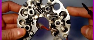
Diode bridge
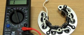
The diode bridge consists of six separate diodes: half of them are positive, the other half are negative. It is necessary to select the “Dial” mode on the multimeter. After this, as soon as the contacts on the tester close, a soft beeping sound will be heard. You need to check in both directions. If a squeak is heard in both cases, then this indicates a breakdown of the diode. Therefore, it needs to be replaced.
We call the diode bridge
When the multimeter probes are positioned as in the following photos, the resistance should be infinite; if the probes are swapped, it should be within 700 Ohms.
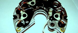
Procedure for checking negative diodes
Checking the positive diodes
Now the auxiliary diodes
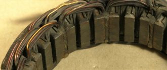
Generator rotor
The rotor is a rod made of metal with an excitation winding. If you look at one of its ends, you can see special contact rings with sliding brushes.
First of all, it is necessary to remove the rod and conduct an external inspection of the winding, as well as the bearings. In some cases, the problem is damage. If everything is in order, then you should proceed to checking with a multimeter.
The device should be set to “Resistance measurement” mode. It should be checked between the slip rings. This value should not be too large - this indicates the serviceability and integrity of the winding.
Note! It is quite difficult to carry out detailed diagnostics of the rotor on your own, so if you suspect any problems, you should contact a car repair shop.
Bearing check
It is also worth checking the bearings, the condition of which determines the life of the future generator. Bad bearings can lead to increased wear of the relay-regulator brushes. If there is something wrong with the bearing, this is usually indicated by an increased hum from the generator or it begins to make noticeable noise. Bearings are checked by external inspection for defects, distortions or contamination. If there are suspicions about their serviceability, then it is better to remove them and meticulously check for the absence of play or wear. The generator usually has two bearings: the first is located in its cover, and the second in its rear part.
Generator stator
The stator looks like a small cylinder with a winding inside it.
Before checking, the stator itself must be disconnected from the diode bridge. First of all, you should carefully inspect the stator, as well as its individual elements, for any damage. Particular attention should be paid to signs of possible burning. Next, you can check with a multimeter by setting the “Resistance measurement” mode. With its help, winding breakdowns are detected. To do this, one contact should be connected to the body, and the other to the winding terminal.
Note! In this case, the resistance must be very high; in fact, it tends to infinite values. If the readings are less than 50 kOhm, then this most likely indicates a malfunction of the stator and the entire generator.
General Tips
Before starting the test, you should always find out in advance which generator set is on the car. For example, depending on the model of the machine, the relay regulator can support different values in the range from 13.6–14.2 V. You need to know this in advance, since in the end all this affects the final result of the test.
Otherwise, there are no particular difficulties, so it is quite possible to identify malfunctions or other problems that happen from time to time with the generator and other elements of the on-board electrical circuit on your own.
If you find an error, please select a piece of text and press Ctrl+Enter.
Source
Generators for VAZ 2106 and 2107
The generator on the VAZ 2106-2107 costs the same as on the VAZ 2101 - G221. If you install additional external current consumers that operate constantly, this will lead to undercharging and insufficient current will be supplied from the relay regulator. These additional devices include:
- powerful audio systems;
- fog lights;
- TV;
- preheater;
- additional heater;
- fridge.
Any similar device will lead to greater power consumption and, consequently, to premature battery discharge, even when the engine is running at high speeds. Standard devices for 2106 were developed a long time ago and are not designed for modern energy-consuming add-ons.
In this case, it is recommended to replace the standard generator with a more powerful unit.
G 222
If you need to increase the current power, then, when deciding which generator is better to install on the VAZ 2106 or 2107, instead of the standard one, take the G 222, which was installed on the VAZ 2105, Nivakh. It would seem that it itself is no better than the standard one on the “six”, but you can take an upgraded version that will be more powerful. Unlike the 221, this unit is designed with a built-in regulator relay, assembled into one unit with brushes. The G 221 gives an output of 42 A, and the 222nd - 50 A. Increasing the cross-section on the rotor winding increases the power, although the design is completely similar to the G 221. However, to install it on the 2106 you will need minor modifications. The easiest way is to install brushes from G 221. They fit perfectly in place of the relay. This modification is quite feasible even for car enthusiasts who do not have the skill.
It can be installed on a VAZ 2106 G222 with a standard regulator, but then it is necessary to change the connection diagram of the electrical machine.
On 2107 everything is installed without problems.
Check the voltage at medium engine speeds at the battery terminals, if it is 14 V at 2500 rpm, then everything is fine. You can drive with a more powerful unit by connecting additional options.
Generator 2108
This installation has greater efficiency, delivering a current of 55 A. It is installed on both 2106 and 2107.
The mount is identical to the standard ones, there are no problems during installation. Just remember to remove the battery terminal. You'll have to tinker with the connection to 2106. There are 4 wires going to the standard device. On the “eight” - three, since the voltage relay is built-in. To get a good result, insulate the black wire, connect the rest according to the standard system. The light bulb - the discharge indicator will light up when the generator is running, and will go out if there is no charging.
It is useful to make some more minor modifications. Instead of the old relay, install a regular power one. Then the light comes on only when the engine starts and at low speeds.
On 2107 you only need to add a power relay.
2107-3701010
An even more powerful installation is from the VAZ 2107i, producing 80 A, which can also be installed on the VAZ 2106–2107. With such equipment it is possible to install any electrical systems. For VAZ 2106 only 2107-3701010 is suitable; You can use any generator of this series for the carburetor “seven”.
When installing this equipment on 2106, it is better to modify it: replace the relay regulator with a similar one from G 222.
Possible faults
Complete or partial jamming of bearings. Symptoms – belt break, incomplete charge of the battery (detected by a warning lamp on the instrument panel, a measuring tester, a load fork).
- visually with the engine running;
- Turn off the engine, remove the belt, and turn the pulley by hand. Failure to rotate freely and evenly indicates the need for repair.
Malfunctions of the stator, rotor. The device is operated in an aggressive environment; dirt and caustic liquids may enter. The insulation of the winding wires is destroyed, causing interturn short circuits to the housing.
Signs – cessation of generation, dim lamp light, indicator light is on, extraneous sounds in the generator. It is checked with the VAZ 2110 generator removed using a multimeter.
The graphite brushes have worn out . Symptoms are the same as in the previous paragraph. Checking and replacement are carried out without removing the equipment. Takes 10 – 15 minutes.
The voltage regulator is not working. Signs:
- Battery charging is insufficient, mains voltage is too low, light bulbs are dim;
- overcharging of the battery, bright light, high voltage, drips of dried electrolyte.
It is tested by measuring the voltage at the battery terminals.
Signs of generator malfunction and ways to eliminate them
The operation of the generator is controlled by a signaling device on the instrument panel. When the ignition is turned on, the window should light up and go out after the engine starts. If this happens, then everything is fine, the generator is working.
Too bright or too weak illumination of the indicator already indicates certain malfunctions of the generator system parts. In any case, insufficient battery charge always indirectly indicates problems with the generator.
The generator does not supply charging current at all
A very common occurrence is low drive belt tension. When it slips, the generator cannot operate at full capacity, and this leads to a gradual discharge of the battery. Belt slipping can also be caused by worn alternator bearings. It must be remembered that the service life of this unit is less than that of the engine, and is about 130-160 thousand km.
If the drive belt tension is weak, the generator cannot operate at full power, which leads to a gradual discharge of the battery
Brush sticking, the second most common problem, is caused by dirt buildup on the brush holder and brushes themselves, as well as weakened brush springs. To solve the problem, it is necessary to clean the above elements and, accordingly, replace the springs with new ones. However, serious wear of the brushes may occur, which will require their replacement.
During intensive use, sometimes the so-called burning of slip rings occurs, as a result of which contact with the generator significantly deteriorates or disappears. This problem can be solved by thoroughly cleaning and grinding the rings or turning them. Additionally, it is worth inspecting the wiring connecting the generator and the battery for breaks.
Also, the reason for the lack of charging current may be a faulty voltage regulator, which must be replaced with a new one. There are frequent cases of breakage of the excitation winding; with some experience in repair work, this can be eliminated. It is also important to pay attention to the fact that there are cases of the rotor touching the surfaces surrounding it. This may lead to partial damage. The cause is usually worn out bearings or seating areas.
When charging current is supplied, but the battery does not charge normally
Often the battery does not take a charge due to poor contact of the “ground” of the generator itself with the “ground” of the voltage regulator
Checking the VAZ 2110 generator with a multimeter on a car
To check the electrical parameters of the car, you will need a combination meter that allows you to set the switch:
- constant voltage within 0 - 30 volts;
- resistance 0 – 5 Ohm, 0 – 200 Ohm, 0 – 2 MOhm.
Step-by-step diagnostic instructions
- Set the switch to DC voltage measurement mode. Use the red probe to touch the positive contacts.
- Measure the battery voltage with the ignition off. The norm is in the range of 12.5 - 12.7 volts.
- Start the engine. Idle speed. Devices and lights are turned off. A value of 13.8 - 14.5 volts is considered normal.
- Turn on power consumers (low beam, fog lights, multimedia devices).
If the equipment is in good working order, the tester will show 13.7 - 14 volts. An on-board voltage below 13V indicates a malfunction of the generator unit. Pressing the gas pedal to increase engine speed should not raise the voltage by more than half a volt. A reading above 15 volts indicates a malfunction of the relay regulator.
Symptoms of malfunction
The following signs may indicate a generator malfunction:
- the warning light on the dashboard is constantly on;
- The battery began to discharge quickly, and recharging does not save the situation;
- there are malfunctions in the functioning of electrical equipment (ventilation and heating, multimedia devices, alarm system and lighting), even if the motor is working properly;
- there was a smell of something burnt in the car interior;
- the generator began to whistle or rustle.
Read also: DIY wooden mechanisms
If you notice these symptoms, you should immediately go to a car service center for a thorough diagnosis. However, you can check the functionality of the generator on your own, especially if you have the skills to use an autotester.
Checking the generator components on the table with a multimeter
Once a malfunction is suspected, the device is dismantled and diagnosed.
- Place the car on a viewing hole or lift the front part with a jack, and place a safety support.
- Loosen the fastening, disconnect the negative terminal from the battery.
- Disconnect the wires from the generator.
- Unscrew the adjusting and mounting bolts.
- Remove the belt.
- Remove the device and disassemble.
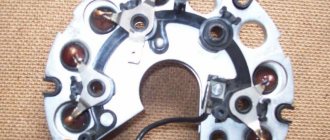
- Checking the diode bridge of the VAZ 2110 generator with a multimeter is performed in resistance measurement mode, range 0 - 2 MOhm. Silicon diodes used in the rectifier circuit, passing a current of up to 80A during operation, heat up. The cooling radiator is a metal mounting ring. Structurally, two types of rectifiers are produced: with an anode and a cathode on the body. Motorists call parts of the first type positive, the second - negative. A working diode in the forward direction shows a resistance of 0 Ohm, in the reverse direction - about 600 kOhm. A zero value in both directions means a breakdown of the device, a high value means a break. Additional diodes are checked in the same way.
- The rotor field windings are tested with a tester at the switch position of 0 - 5 Ohm. Test leads are connected to slip rings. The resistance value ranges from 1.8 – 5 Ohms. Less is a short circuit, more is a gap.
- The stator windings are tested in the range 0 - 200 Ohm. Alternately touching the terminals of two serviceable windings will show units of Ohms on the instrument indicator; the absence of readings means a malfunction.
- The integrity of the winding insulation is measured by touching one probe to the winding contact, the other to the housing. An infinitely large value indicates normality.
The final confidence in the serviceability of the generator will be given by testing on a bench.
Source
Malfunctions of rectifiers on cars
A malfunction of the rectifier bridge can be detected if:
- When the engine is running, the battery icon on the instrument panel lights up or flashes; when you turn on the ignition, the indicator should light up. After starting the engine - go out;
- When the ignition is turned on and after the engine starts, the charging indicator with the battery icon does not light up in both cases;
- The brightness of the headlights directly depends on the engine speed. At the same time, car light bulbs burn out more frequently;
- The starter turns, with difficulty starting the engine, or does not turn at all.
If you encounter the problems described above, this means that it’s time to work on the generator. These are indirect indicators of a malfunction of the diode rectifier, but it is not yet a fact that the bridge is at fault. The culprit in this case may be the relay regulator or the generator itself. Therefore, further verification needs to be carried out.
First of all, check if the belt is loose. Insufficient belt tension causes slippage. And this prevents the generator from working normally. After checking the belt, if everything is fine with it, we check the relay regulator. And only after this we begin to check the rectifier bridge. By the way, be sure to check the battery. The terminals must be clean and the wires securely fastened to them.
How to check a diode bridge with a multimeter
This check can be done without removing the generator from the car. To do this, you will need a multimeter (tester) and free access to the back cover of the generator. If access is difficult, it is better to remove it. In any case, disconnect all external wiring from the generator and remove the voltage regulator.
After that, take a multimeter and set the switch to diode testing mode. If it is not there, then we set the resistance to at least 2 kOhm to measure. Next, we connect one of the probes to the positive terminal 30 of the generator (a stud on which usually two to four wires go and are secured with a nut), and connect the second one to ground (housing). Then we swap the probes. In one case, the measuring device should show a certain resistance, in the second - infinity. This way the entire circuit of the rectifier bridge is checked. If the tester shows the same result in both cases, then the rectifier bridge is faulty.
Checking the bridge using a test light
For further and more accurate checking, it is best to use a test light. If it is not available, we assemble a simple circuit. To do this, you will need two pieces of electrical wire, one meter each, a light bulb (can be removed from the rear light of the car) and a battery. We connect one wire to the negative of the battery. We cut the second one in half and connect a light bulb into the gap. We connect this wire to the battery positive. Our stand is ready for use.
Now you can continue checking. We connect the negative cable of the battery to the generator housing. The positive one with a light bulb - with one of the diode rectifier mounting bolts. If the light comes on, it means there is a malfunction inside the generator.
Then we connect the plus of the battery to terminal 30, and connect the minus to the bridge mounting bolt. If the light is on in this case, this indicates the presence of a short circuit.
How to check the diode bridge of a VAZ-2110 generator with a multimeter
The stable and smooth functioning of the electronic components of the VAZ-2110 largely depends on the performance of the autogenerator. It supplies power to all components of the car and also assists in starting the engine. For this reason, the owner of the car must periodically monitor its performance, and in case of failure, understand how to check the diode bridge of the VAZ-2110 generator with a multimeter.
Testing of the diode bridge (DM) is included in the set of tests for the generator on the VAZ-2110 in case of malfunctions. DM failure is not the only reason for a generator not working. This also includes: voltage regulator, brushes, capacitor, electric stator and rotor windings. All these components can be checked with a regular household multimeter, saving money and time on visiting a car service center.
Selection of diodes for the rectifier bridge
The main thing they look at when choosing a diode is power. It depends on the highest rated current produced by the generator. The higher the generator power, the more powerful the diodes. Diodes for the rectifier bridge are conventionally divided into categories:
· low power diodes, current 300mA;
· medium power diodes, current 300mA – 10 A;
· high power diodes above 10 A.
Diodes are divided according to the type of material used, these are germanium and silicon. Most manufacturers prefer silicon diodes. The main reasons for choosing silicon diodes:
· low reverse current;
· high permissible reverse voltage up to 1500 V;
· performance of silicon diodes from -60 to +150оС
Germanium diodes have a low reverse voltage value of up to 400V. They operate in the temperature range from -60 to +85°C.
For example, to replace diodes for a Bosch generator with a 140A for a Touring Custom car. For such a generator you need 50A diodes, for example, Cargo 50A 138634 and Cargo 138635, for a 140A generator you will need 12 pieces, for an 80A generator 6 pieces.
The role of the diode bridge and the reasons for its failure
The DM in the design of a car generator converts direct current characteristics into alternating ones; it is also often called a rectifier.
The main purpose of this device is to charge a car battery with operating current parameters.
- Changing current characteristics.
- Blocking the passage of current to the electrostator winding. So it works on the principle of a one-way valve.
- Increasing the electrical power characteristics of the generator.
Factory-made DMs are made in the form of a monolithic structure, which ensures their compactness, reliability and budget cost. However, the non-demountable design also has its disadvantages. If one diode fails, you will need to purchase a new set.
The DM is made of 6 converter diodes with bipolar rectification technology. Rectifier diodes in this bridge design act as an obstacle that passes current in one direction, preventing current from the on-board network from entering the stator windings. Because these diodes operate in a stressful environment, they break down frequently.
The main reasons for diode failure on the VAZ-2110:
- Water penetration during car washing. The most common reason.
- Dust and oil contaminants entering the generator during long trips.
- When a car enthusiast tries to “light the car” when the battery is completely discharged, if he also mixed up “+” and “–”.
Disassembly and removal of the generator
If the generator is not working, in order to diagnose all critical components for operability, you will need to disassemble it.
Algorithm for disassembling the generator for testing for performance with a multimeter:
- Before ringing the generator, disconnect the battery by removing the “–” terminal from it.
- Disconnect the pink wire responsible for starting the generator. Remove the fastening nut from the “+” bolt.
- Slightly loosen the tension of the nuts at the top and bottom, unscrew the tension bolts, and remove the belt.
- Turn the generator at a right angle. After this you can remove the bottom bolt.
- Perform an external inspection of the housing and clean it.
- Before testing the generator, the bridge is dismantled for testing.
Checking status
Checking the diode bridge is quite simple, even on your own. There is no need to go to a service station.
All you need is a multimeter.
We connect the positive probe of the multimeter to the diode bus. Similarly, we connect the negative probe to the negative terminal of the diode bridge. Now let's look at the device readings. If all is well with the rectifier, then you will see readings close to infinity on your multimeter. If none appear, then there are problems with the device and you will have to change it. But that's not all
Now the probes should be swapped, that is, the minus should be connected to the plus, and the plus to the minus. Let's look at our multimeter again. What do you see there? If several hundred ohms, the unit of measurement for resistance, are displayed, then the unit is operating normally and is in good working order. To check the additional diode, if any, repeat the same steps described above in our instructions.
Replacement
If checks show that there is something wrong with the diode bridge, there is nothing left to do but replace the device. There is nothing complicated about this. Especially if you have already had to disassemble the generator or at least remove it.
Follow the proposed algorithm and additionally rely on video instructions. This will help you cope with the task.
- Disconnect the battery. To do this, just remove the negative terminal from it.
- Disconnect the pink wire that turns on the generator. To do this, you will need to unscrew the mounting nut from the positive bolt.
- Loosen the tension of the upper and lower nuts slightly, unscrew the tension bolts, and remove the belt. You can put it aside for now.
- Rotate your alternator 90 degrees so you can remove the bottom mounting bolt.
- Carefully inspect your generator housing. The rectifier housing may need to be cleaned. If there is contamination on it and on the connections, it would be a good idea to clean it. This will allow the new device to function more efficiently and effectively.
- Try to be as careful as possible, but at the same time thoroughly clean the inside of the ring.
- Remove the old diode bridge and then perform the reassembly procedure.
- Start the engine and check the functionality of the new rectifier.
Dismantled element
Reassembly is carried out in strict sequence, taking into account the individual design features of the new generator rectifier.
Based on the materials provided and the replacement instructions, you should be able to complete the task without any problems. But if problems arise, be sure to contact a specialist.
Loading …
Checking the VAZ-2110 generator with a multimeter
Before ringing such a self-oscillator, you need to understand that this process is multi-stage. In fact, it consists of several basic tests: checking the electronic bridge and the regulator relay, as well as additional tests of the stator-armature winding, capacitor and brushes.
Continuity of the diode bridge
The bridge consists of 2 parts: power and auxiliary diodes. A working diode towards the battery should show a resistance of about two to three hundred Ohms, and in the opposite direction it tends to infinity.
- We connect the multimeter probe with o to the “+” diode bus.
- We connect the multimeter probe to the “–” diode bus.
- Analyze the readings of the device: when the value of infinity appears, the diode is working, and if the result is different, it will need to be replaced.
- Change the location of the probes.
- The meter readings are analyzed. If the value on the screen is several hundred ohms, then the diode is working.
Regulator testing
The VAZ-2110 generator voltage regulator is responsible for maintaining a constant output voltage of the generator. When the car is in motion, the rotation speed of the generator shaft changes all the time in the range from 12 to 20 V. The regulator must keep a constant value. The normal charging of the battery and the operation of all electronic components depend on this. Unstable voltage can lead to premature vehicle failure.
Before checking the generator, you need to make sure that the generator relay is working. You can use a multimeter. Connection points for generator output or battery terminals. Checking the generator diode bridge should show a normal voltage of 14 V for any number of crankshaft revolutions.
Before checking the voltage regulator, you will need to invite an assistant to press the accelerator several times. The connected multimeter is turned on in the voltage version. Several measurements are taken to avoid errors. The measurement run-up should not be higher than 0.5 V. Otherwise, the relay will not work correctly.
Trouble-shooting
There are two main options for solving the problem. The first is accurate diagnostics on the bench: after detecting signs of burnt-out diodes, a check is carried out and it is determined which elements have failed. After this, the faulty diodes are soldered off, and new ones are soldered in their place. It is very important to take exactly the same brand; any analogues will not last long.
It is much easier to change the assembly, it is faster and of better quality, since you can be sure that the spare part will last for some time. The price of the part is low, for example, on a VAZ 2110 it is about 650 rubles. Replacement is not difficult and can be done independently.
Identifying a faulty diode bridge and replacing it is not difficult for any car enthusiast with a minimum set of tools. If the check shows a breakdown, it is best to remove the generator and carry out repairs. The process is simple and takes no more than an hour.
Additional testing of generator components faults
The stable operation of this device can be affected not only by the DM and the relay regulator, but also by the electric rotor and stator windings, brushes and capacitor. If the first measurements do not reveal any malfunctions in the operation of the main generator components, then proceed to additional testing of the generator components.
Generator winding testing
This type of measurement is carried out on a dismantled and disassembled generator. You will need to separately check the serviceability of the rotor and stator windings. The meter is set to ohmmeter mode at a value of 200 Ohm.
The main stages of monitoring the electric rotor and stator windings:
- Measure the resistance value on the rotor windings. For this purpose, probes are connected to the outputs of the windings. The normal value is above 5 ohms, if less than 1.9 ohms, there is a turn short on the rotor. Most often, the electrical circuit breaks in the connection areas between the rotor winding and the ring. It is possible to determine the malfunction by moving the wire in the soldering area with a probe. Alternatively, integrity may be compromised here.
- Carefully inspect all connections. It is possible that dark and damaged wire insulation will be detected, which is a consequence of a break and short circuit.
- We call electrical circuits to determine the short circuit on the housing. To do this, the first probe is brought to the rotor shaft, and the second to any ring. If the winding is working properly, the ohmmeter reading will go off scale. If the resistance is low, this winding must be rewound. In this case, perfect balancing must be maintained.
- Before checking the stator, a visual inspection is performed, paying attention to all kinds of external damage to both the housing and the insulator, as well as the places where the wires from the short circuit are burned.
- If a defect is detected, the stator is sent for rewinding.
- If no external abnormalities are found on the stator, examine it with a multimeter.
- The stator must be disconnected from the generator and removed.
- The multimeter is set to resistance control mode. Initially, the probes are installed on the 1st pair of terminals. Then they test a pair of windings “1–3”, and then “3–2”. If the analog multimeter needle goes off the scale, the windings will need to be rewinded.
- To check the generator for the absence of a short circuit between the turns and on the housing. The first probe is connected to the terminal, and the second to the body. If the windings are short-circuited, the multimeter on the scale will show a lower resistance value than on the working ones.
How to determine generator malfunctions
Signs of a faulty generator diode bridge. A car generator and a generator, a household power station are similar. Accordingly, the principles of troubleshooting and repair are the same. The only difference is that the car generator contains a rectifier and a voltage regulator, so the car network is designed for 12 Volts. The article discusses generator malfunctions and how you can fix them yourself. Your vehicle is equipped with a warning light that can alert you that the alternator has lost power. If this happens, you need to make sure that the sensor is working and the lamp is connected correctly.
It often happens that these lamps use a bad connector or the control relay fails. It is also possible that your battery, charging terminals are faulty, or it is simply discharged. When there is a lot of energy consumption, for example, when using lighting devices to the maximum, charging, or leaving the radio on overnight. Generator malfunctions may occur due to increased energy production when the voltage is above 14-15 Volts. The numbers vary depending on the model.
Therefore, if the battery breaks down, you should always check the generator too. Sometimes the generator begins to deliver current below the required limit of 13.2 Volts, then it is urgently necessary to check it for damage.
Before removing the generator, it is necessary to check the tension of the drive belt. Lack of electrically conductive connections between the battery or generator and the car body; voltage may be lost “on the way” to the battery. Also check the bearings for clearances and the integrity of the fuses.
For some types of faults there is no need to remove the generator. If there are knocks or noise during work, it is necessary to disconnect the wires: the noise will disappear - but a short circuit will form, unfortunately, these are expensive repairs, their cost exceeds the price of new equipment.
The noise remains - replace the bearings, they have worn out during use. Check the brushes, maybe it's time to replace them too. The contact brushes and rings may not be pressed well, then the spring should be adjusted. Get rid of dirt and burnt marks on the rings, if any. Sandpaper is the best way to remove scorch marks. If the rings become unusable, the rotor must be replaced. Check the rotor contacts with a multimeter.
Generator malfunctions in the form of a damaged rotor must be removed in the following order. Since a faulty rotor cannot be replaced, it must be completely replaced if it fails. The same applies to the stator. Remember that the rotor and stator must not have electrical contact with the body or other parts of the vehicle. A faulty stator must be replaced. Voltage rectifier diodes should not conduct current in both directions.