Give it a repost, let people read it carefully, it will save nerves, a relatively “large” amount of money to repair the generator (especially “large” when there is no money at all) and the time spent on all this, a drained battery, and God forbid a fire!
The new generator works stably, but the voltage is kept low like all generators similar in design. Without consumers 13.9 volts, headlights 13.7 with the heater at speed 2 (this is not enough), and if the rear window heating is turned on with the heater speed 2 it drops to 13.2 volts. This is an ass. In the summer it may still be normal, but in winter the frozen battery not only does not charge at all for the first 15 minutes in frost minus 25, but such a low voltage is not enough for normal charging. And considering that I go to work like a donkey by 8 am (it’s usually dark here), and I leave work from the office at 5:30 pm, that is, it’s already dark again, then in fact the generator will always produce low voltage due to the headlights, heater and rear window , the battery will not hold its charge and density properly and will gradually run out...
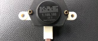
The trick of this regulator is that the voltage regulator on it looks at the voltage not at the + terminal, but at the voltage at 3 additional diodes. I know this problem, and I know how to easily solve it. Thanks for this article. Let's go to the store and buy the CORRECT voltage regulator. I read which ones work better. Exactly the one in the photo. With a square tablet. These brushes are the most stable in terms of quality and stability of work. The trick of this regulator is that it looks at the voltage at the + output of the generator. Among the additional features of this regulator: The charge indication lamp can actually show the absence of this very charge, as well as if there is an overvoltage in the event of damage to the diode bridge, for example. If this chain dies, it will still work normally. The regulator is independent. Another huge plus is that until the generator spins up, it does not get excited. And does not create a load for the engine. That is, until the engine starts, the generator does not provide a load, this is useful during cold starts when every penny of energy counts
Extremely simple installation of this regulator:
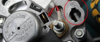
We bite off the tips and connect 2 terminals. The hole that goes to the winding should be 8mm! Read why below. it is important
I was very surprised that the tablet is noname
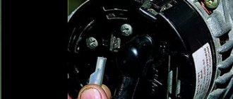
Don’t forget to remove the diodes or cut the jumper
Now I STRONGLY recommend paying attention HERE This applies not only to converted generators, but in general to all generators of a similar design
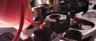
The fact is that these generators often burn. Well, in the literal sense, it also happens, but most often the diode bridge burns in them. As a techie, I quickly realized why. And I was very surprised at how down at the factory they came up with this design. The contact on the diode bridge is a platform. A ring winding contact is placed on top. On many generators it is soldered. Here it’s just a ring on a ring. and the MOST creepy thing is that everything is pressed with a TEXTOLITE WASHER BEHIND ITS CENTER! Moreover, the washer on top is NARROW and thin, bending it inward, and some MORONI stuck a GROVER in there! GROVER CARL! It simply bends both the washer and the tectolite washer, too. Naturally, these generators burn, since the textolite stupidly bends like a satellite dish, the 2 contacts are not pulled together normally on the diode bridge, and they need to be pulled not by the center, where they are not, but by the contacts themselves, and this edges... sort of... and...
The diode bridge just melts.
It’s enough to just walk around with the words “KZATE generator burned out,” “KZATE diode bridge burned out,” and that doesn’t only apply to them. This applies to many...whose windings are not soldered
I decided to solve this problem in advance. A washer with an internal diameter of 8mm is placed on top of these 2 connections. A piece of SOFT plastic tube, approximately 1 mm in size, maybe a little larger in location, is inserted into the washer (for centering so that it does not short to the bolt! This is ATTENTION!). This is done to press on the edges. and not behind the center. A native textolite washer is placed on top of this washer (as an insulator), on top of another metal washer, preferably thicker, with an internal diameter of 6 and an outer diameter of approximately 10. The bolt is simply screwed on top. There shouldn't be ANY GROVERS there. The plastic sleeve is needed so that the washers are centered and the bolt does not touch what is UNDER the textolite washer. That is, we get the design 1. Bridge and contact pad on it 2. Ring contact of the winding (there is an internal 8 external 10) 3. Washer internal 8 external approximately 10 4. Textolite washer 5. another washer only this time internal 6 external 10 6. Insert bolt and tighten it
How to check the operation of the generator
The battery in a car is an important element of the system, which is responsible for providing the car’s on-board network with electricity.
The generator is used to charge the battery while it is active. Unstable operation of a device generating electricity causes a voltage drop in the network and failure to restore the capacity of the power source. Normal generator performance means timely and complete replenishment of the battery charge level, which decreases under load. Checking the battery charge level from the generator is simple and can be done by the car owner himself. Diagnostics of an automotive energy-generating device includes a visual inspection of the unit, its elements and related parts, as well as voltage and current measurements. At least twice a year, you should check the tension of the drive belt, excessive weakening of which leads to a decrease in the performance of the generator, and sometimes can lead to breakdown of the device.
Diagnostics of indicators such as voltage, current, resistance are also necessary twice a year. To carry it out, you will need special devices - a voltmeter, multimeter or load fork.
It is traditionally believed that 13.5-14.5V should be supplied by the generator to the battery and this is absolutely enough to replenish the battery costs.
It is worth considering that using a battery with a higher power in a car than the manufacturer recommends also requires the installation of a more productive generating device.
It is necessary to take into account the load that the generator must withstand - it is calculated based on the maximum indicators of all electrical appliances and car systems.
Do not forget that the charging current from the energy-generating device will allow you to start the car in the cold season. In order to avoid problems with starting the car, we recommend purchasing generating equipment, the charge current of which will be approximately 10% of the capacity of the power source.
That is, a battery of 100 A/h requires a generator that can produce 10A. Please note that for many cars, 100 amp equipment will operate at its maximum capacity, because the power consumption of the automotive system is in the region of 80 amps. Therefore, the choice of a source generating energy must take into account both the battery capacity and network consumption.
The potential difference can be diagnosed in two ways - directly at the generating equipment and through the battery. The generator is directly connected to the power source with a thick wire, therefore, to check the level of potential difference, you can measure the voltage at the power source. To do this, you will need special devices - a voltmeter, multimeter or load plug.
The wires of the first measuring instruments are connected to the battery in any sequence. The plug must be connected to the battery terminals with strict observance of polarity. It is generally accepted that the normal voltage in the network should not be lower than 12 volts. At idle speed without turning on all the electrical appliances of the car, this indicator should be at the level of 13.5-14V. A drop in voltage values to 13.3-13.8 volts is considered acceptable.
At the same time, using conventional testing equipment, you can check the resistance of the generator elements - rotor, stator and diode bridge. Diagnostics of rotary equipment is carried out by its winding. It is necessary to connect the probes of the device with slip rings. If the multimeter gives readings from 2, 3 to 5.1 ohms, then this element is working. The current consumption of the winding should be within 3-4.5 amperes.
Its normal resistance is 0.2 Ohm. The diode bridge is checked by the presence or absence of resistance, the indicators do not matter. The only thing worth considering is that there should not be a zero dimension. Measurements are carried out in pairs - positive output and all plates on this side or minus and all elements.
We remind you that for normal charging of a car battery, the voltage supplied by the generator must be from 13.5 to 14 volts.
The current strength required by the electrical system of each car is individual and depends on the number of electricity consumers and their values. And also the charge current must be sufficient to charge the power source.
Also interesting: Niva Chevrolet installation of air conditioning - Auto magazine MyDucato
It is worth noting that ampere readings appear only when there is a load in the vehicle’s electrical system and, accordingly, the battery is discharged. After starting the car engine, the charging current is about 6-10 amperes and drops over time, because the battery is charging, taking on the main energy consumption. If you turn on additional equipment - headlights, radio or heated mirrors, you can see an increase in the charging current values.
Wiring and connections
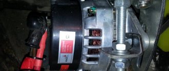
One of the weakest points in the power supply circuit of the Niva (and any other car) is the connection of the power wire to the generator. The device is located low and is practically not protected from water and dirt. Even if this connection looks normal, it makes sense to disassemble it and inspect the contact point. We disassemble, inspect, clean if necessary, apply conductive lubricant, and assemble.
The next weak point is the connection of the negative wire of the battery to the engine. It is not located in the best place and is constantly dirty. As a result, the connection oxidizes and good contact is lost. We do the same thing: disassemble, clean, assemble.
It is also worth inspecting the terminals on the battery terminals. They may be oxidized (white coating) or loose. Clean, apply conductive lubricant, tighten.
Otherwise, the wiring and connections on the Niva behave quite correctly, but this does not mean that all this will last forever. Let's not be lazy, inspect the connections and wires. If necessary, we call.
21.6.3. Removing generator 371.3701
We carry out the work on an inspection ditch or a lift. Use pliers to loosen the clamp of the rubber air intake.
Remove the air intake from the branch pipe of the generator protective casing.
We disconnect terminal “61” of the generator.
Sliding the rubber cover, use a 10mm wrench to unscrew the nut securing the wires to the generator output extension 30.
Using a 17mm socket, unscrew the nut securing the generator to the tension bar.
Using a 19mm spanner, unscrew the nut of the bolt securing the generator to the bracket...
We take the generator out of the engine compartment downwards.
Rubber and metal bushings are installed in the eye of the rear cover of the generator.
Using a “10” wrench, unscrew the nut of the insulating sleeve of the generator output extension “30”.
...and internal insulating sleeves.
Using a slotted screwdriver, unscrew the two screws securing the protective casing to the generator.
Remove the protective cover.
Disconnect the wire from terminal “61”.
Using the “10” key, unscrew the “30” terminal extension.
Disconnect the wire from the voltage regulator.
Using a Phillips screwdriver, unscrew the two screws securing the voltage regulator and brush holder.
Remove the voltage regulator with brush holder.
Using a 19mm wrench, unscrew the generator pulley nut. You can stop the rotor from turning with a screwdriver (do not bend the impeller).
Remove the washer from the shaft...
Use a screwdriver to pry it off and remove the segment key...
...under which there is a washer without a keyway.
Using a 10mm wrench, unscrew the nut securing the capacitor terminal.
We remove the terminal and, using a Phillips screwdriver, remove the capacitor.
Using a sharp scriber or paint, we mark the relative positions of the covers and the stator for subsequent assembly.
Using a 10mm socket, unscrew the four nuts of the coupling bolts.
Remove the front cover.
To replace the bearing, use an “8” key from the outside of the cover to unscrew the four nuts of the screws securing the plates.
Remove the plates with screws.
Use a tool head of a suitable size (or a piece of pipe) to press the bearing out of the cover.
There is a thrust ring located on the rotor shaft.
We screw a nut onto the shaft thread, clamp it in a vice and jerk off the back cover with the stator.
If it is difficult to remove the rotor, tap its end with a soft metal drift through the voltage regulator window.
We disconnect the rotor and stator.
Use a puller to press the bearing off the rotor shaft.
Using the “8” head, unscrew the three nuts securing the stator terminals to the rectifier unit.
Use a screwdriver to pry it off and remove the stator.
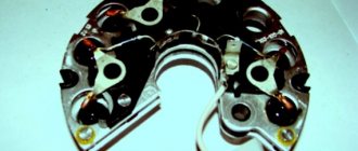
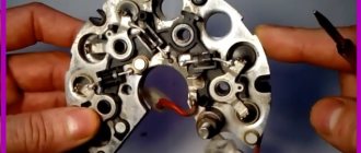
Remove the rectifier block.
Remove the contact bolt from the rectifier block.
A) Belt break.
Carefully examine the presence of a belt on the water pump and generator pulleys. To return it to its destination, you will need socket wrenches 17 or 13, depending on the year of manufacture of the car, as well as a strong flat-head screwdriver.
Disconnect the HF position sensor (for example, at 21213,21214).
Loosen the nuts securing the tension bar and slide it to the side towards the cylinder block.
Put a belt on your professionalism landing place.
After installation is complete, adjust the tension, controlling the deflection when pressing with a huge finger on the clearance of the belt between the generator and pump pulleys - 10-15 mm, pump and crankshaft - 12-17 mm. Failure to comply with this requirement may result in the belt slipping with subsequent damage and rupture.
What is a generator
A generator is an alternating current device that produces electromagnetic excitation during operation. The generator design has a built-in rectifier unit, equipped with diodes made of silicon, as well as an electronic voltage regulator.
Thus, the unit creates electrical energy from mechanical energy and energizes the car’s battery, and also provides energy to its devices and systems. The connection diagram for the generator on Niva-2121, 21213, 21214 is shown in the figure.
Device Description
On Niva 21214 cars there is a generator of type 9412.3701, on VAZ 21213 - type 371.3701, on Niva Chevrolet there is a generator 2123. All of them are alternating current electric machines with electromagnetic excitation, having a built-in rectifier unit with silicon diodes and an electronic voltage regulator.
The maximum current produced by the generator unit type 9412.3701 is 80 A, voltage - 13.2 - 14.7 V, rotation - right. Design of unit 21214
The unit covers are attached to the stator using 4 bolts. The covers have bearings installed. They rotate the rotor shaft. In the front bearing, the inner race is clamped with a nut along with a thrust ring and washer. The 2nd bearing is also pressed into the back cover.
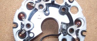
The stator has a 3-phase winding, one of the ends of which is connected to a rectifier unit consisting of 6 diodes. Of these, 3 diodes are negative, 3 are positive. According to the polarity, they are pressed into the plates. The entire structure consists of a rectifier unit, which is located on the back cover of the generator unit covered with a protective casing.
The design of the unit also includes contact rings and brushes. On the back side of the back cover there is a brush holder, which is structurally connected to the voltage regulator. The rectifier contains a capacitor that protects the electrical network from power surges.
The “B” terminal of the generator set must be connected to the positive terminal of the battery, and the negative terminal of the battery to the vehicle ground. If the connection is incorrect, this will lead to breakdown of the diodes.
Generator Niva 21214
Characteristics of the standard generator
The main characteristics of the generator installed by the manufacturer in Niva 21214, 21213, 2121 will be considered using the example of generator type 9412.3701:
And also interesting: Do-it-yourself tuning of the Niva 2121 interior: video instructions
The cost of standard models of electric generators is 5-7 thousand rubles. If the unit breaks down, it is possible to replace its components or completely replace it with the original or analogues. The prices of the most common ones are presented in the table.
| Analogue | vendor code | Cost, in rubles |
| Generator VAZ-2104-21073,21214 | 9412.3701-03 | 5900 |
| Generator VAZ-2104-21073,21214 | 372.3701-03/05 | 3800 |
| Generator VAZ 2121-21213,21214 | 9412.3701 | 5450 |
The table shows that in the process of replacing a generator on a Niva, you can give preference to a cheaper universal analogue.
Signs of a generator malfunction
During the operation of any car, unpleasant situations often arise in the form of failure of one or another element. Niva is no exception, and most often the generator suffers.
If the generator seems to be faulty, it is recommended to check its functionality using a multimeter. To do this, you will need to start the engine and check the voltage at the battery terminals. The standard value that a multimeter should read is 13.6 V.
If the readings during measurement are higher, it means that a break or short circuit in the windings has occurred in the structure. The same can be said about the case when the voltage is below the specified number. This procedure is carried out regardless of the engine: injector or carburetor.
Also, if the breakdown is caused by another reason, you can replace the generator itself. Usually, for replacement, they turn to special service stations, but if necessary, the work can be done with your own hands.
In modern cars, breakdowns of the electrical system are one of the most common. A large number of electronics requires particularly careful monitoring of the operation and condition of the generator and battery, because their failure can immobilize the car. The most common signs of a generator malfunction are:
If you notice incorrect operation of the car, then perhaps the battery charging current from the generator is insufficient.
All malfunctions of electrical equipment, which includes the vehicle’s energy-generating device, are mechanical (deformation or breakage of fasteners, housing, malfunction of bearings, pressure springs, drive belt, etc.) or electrical (winding breaks, diode bridge malfunctions, burnout or wear of brushes , short circuits between turns, breakdowns, etc.).
Don’t write off a non-working generator: find out if there are repair kits and spare parts. Replace them if possible. If you cannot carry out repair work yourself, then take the generator to a workshop. Many craftsmen will be able to restore the unit at no extra cost and in the shortest possible time.
However, some breakdowns require the purchase of a new device that generates electricity. For example, a failing bearing that is soldered into the generator housing cannot be restored or replaced in most cases.
Remember that failure of this unit can be caused not only by wear and corrosion, but also by poor quality of elements and components; excessive load; external influence of salts, liquids, temperatures.
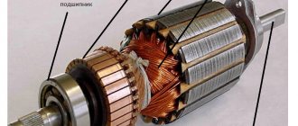
Winding
The stator winding is made of a star, which means a common output of wires, and is three-phase. The reverse part of the winding wires is attached to the rectifier bridge. It is designed in such a way that it contains three negative diodes and three positive ones - a total of 6 silicon valves. They are mounted in arc-shaped plates made of aluminum alloy. The principle of polarity is observed, so the plates and diodes are divided into groups, but in the end they are all connected to the rectifier unit. It is located on the back wall of the device. To get to it, you need to remove the plastic casing and then unscrew the cover bolts. An additional trio of diodes is located on one of these plates. They provide power to the generator excitation winding. The process begins after the device is put into operation.
The generator of the VAZ 21214 car is designed in such a way that the winding is located on the rotor, and its terminals are soldered to the rings. They are mounted on a shaft, in the amount of two pieces, and are made of copper. Two carbon brushes provide power to them.
Among other things, the generator of the VAZ 21214 car has slip rings of reduced size. Due to this, the service life of the brushes increases and the peripheral rotation speed becomes lower. The brushes are fixed in the housing using a special holder, which, in turn, is mounted on the back cover of the device and has a common unit with a voltage regulator. If the regulator breaks down, it must be replaced, since it cannot be repaired. The reason for this is its non-separable body.
Generator VAZ 21214
Nuances
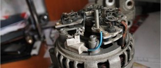
When replacing a generator with a Niva 21213, 2121, 21214, a number of subtleties arise, and one of them is the location of the generator unit. It is located at the bottom of the engine compartment.
Actually, this is why problems arise with the operation of the structure: while driving, various contaminants get on the generator, and coolant drips. If you don’t want to constantly change the generator unit, it is recommended to move it upstairs.
To ensure that no problems arise during the operation of the car, it is important to monitor the condition of the car. First of all, it is recommended to regularly inspect the generator.
So, when the “battery” light blinks on the dashboard, if suspicious noises or creaking sounds occur, you should be wary and think that the generator is not working correctly.
Timely inspection will help to avoid unpleasant situations in the form of breakdowns of the constituent elements of the generator, and as a result, failure of entire electrical systems.
Read news about the new Niva
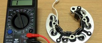
D) Diodes or rectifier unit are faulty
To assess the condition of the mentioned components (negative, positive and additional diodes), arm yourself with a low-power lamp and battery. Diodes are indicated by numbers in the diagram: 1. Positive
Operation is determined by connecting “” to the 30 terminal of the generator (for positive), the bolts of the rectifier block (for negative) or to 61 (for additional), and “-” to its body (for negative) or to any of the bolts of the rectifier block (for positive and additional). The glow of the lamp indicates that the diodes have been shorted, which leads to the conclusion that the diode bridge will have to be replaced. Be attentive to the indications on the instrument panel. Often the icon lights up half-heartedly and is not noticeable in bright light.
Read also: Where Does Engine Oil Go?
Battery charging lamp VAZ 21214
After replacing the alternator belt, charging
, as a result, the battery died and the controller stopped working. The location where the charging relay is located near the Niva is determined by the age of the car. Yes, remote relay
can be found on the right fender liner of a car with a classic engine compartment layout. More modern modifications of generators are equipped with a launch vehicle combined with a brush assembly.
The element is not repaired, but replaced completely. To assess the condition, you will need power supplies of 12-14 V, followed by replacement with 16-22 V, and also an incandescent lamp of 1-3 W. According to the diagram drawing, apply current to the voltage regulator in series. If the first test is characterized by the operation of the lamp, and the second - by the absence of glow, then the LV is working.
If there is a break, the lamp will not light up at all; if there is a breakdown, it will glow constantly. In addition, weak charging, as well as its absolute absence, is often explained by abrasion of the brushes (residual height less than 5 mm) and slip rings of the generator. If the first part is changed along with the brush holder, then the second is restored by grinding, grooving or removing the remains of the old rings and pressing in new ones. It is recommended to supplement the disassembly of the unit with a total cleaning.
Source