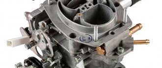
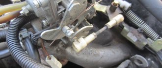
Schematic diagram of a carburetor on a VAZ classic
The correct operation of any automobile internal combustion engine depends entirely on how well the mixture of liquid fuel and air is prepared, and also on how much of this mixture is supplied to the engine. In addition, it is prepared in carburetors. Another important task of these units is the correct and uniform distribution of the fuel mixture among the engine cylinders.
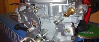
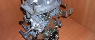
Any DAAZ carburetor has several components in its design. These are a diffuser, jets, a float chamber, and a throttle valve.
Modifications of VAZ carburetors
If the car is equipped with an old engine, then the device is also of an old modification. Newer engines, which have a vacuum ignition corrector in their design, have newer, improved elements installed. This is a DAAZ 1107010 20 carburetor.
The devices are manufactured at the Dmitrov plant, where they produce not only these parts, but also other devices for cars.
Carburetor - complex and precise
The DAAZ carburetor is considered a rather complex device. In its composition you can find many different units and components. An ordinary, and especially a beginner, car enthusiast does not need to know all the elements. This is only necessary for those who provide professional tuning, adjustment, repair and other maintenance services.
But we will not be afraid of the difficulties and the huge number of components and will look at the design of the DAAZ carburetor specifically.
We will consider a device for the VAZ 2107. Among many other parts in the design, the float chamber stands out.
The unit contains such important components as a throttle valve and an air valve. In addition to these components, you will find jets in the design. Liquid fuel is atomized in the unit - special parts are used for this. And the most important components that can be found in the design of this device are diffusers. They are nozzles. With their help, the air flow configuration is created.
Cleaning the jets
Before adjusting the carburetor, it is necessary to clean the channels and jets of dirt and deposits. To do this you need:
- unscrew the fuel and air jets;
- soak them in acetone or some other carburetor cleaner for ten minutes;
- blow out the jets with compressed air;
- Install cleaned and dried jets into the carburetor.
Before adjusting the carburetor, it is necessary to remove and wash all air and fuel jets.
Working with a carburetor is associated with an increased fire hazard. All precautions should be taken before starting work.
The VAZ 2106 carburetor is a rather complex device consisting of many small elements. Nevertheless, any car owner can wash the jets and strainer, as well as adjust the supply of the fuel-air mixture. To do this, you just need to consistently follow the instructions of the specialists.
How does the DAAZ 1107010 carburetor work?
At the moment when the flammable liquid is in the float chamber, the amount of fuel is regulated using the float. When it floats up, the needle valve will block the access for gasoline that wants to get there. In this regard, this camera is similar in principle to a toilet cistern. However, the fuel supply is not instantaneous. First, it must be passed through a series of filter elements. There the liquid can be cleared of various impurities.
The liquid will then enter the fuel chamber. There are two of them in this unit. The DAAZ 2107 carburetor has fuel jets in its design. They are necessary for the passage of fuel.
In addition to fuel jets, there are also air jets through which air flows.
However, this is not the end of the matter of preparing fuel for internal combustion engines. Before the emulsion enters the cylinders, it passes through the econostat. At this stage, the combustible mixture will be enriched.
Now, using the same spray system, fuel is sent to diffusers. This stage is almost the final one. The DAAZ 2107 1107010 carburetor is designed so that drops of fuel in the diffusers are attracted by a powerful air flow. As a result, the mixture of air and flammable liquid will reach the central part of the chamber, where mixing will occur.
The DAAZ 2107 carburetor, among other components, has jets that operate at idle. This mode differs in that the fuel emulsion is consumed only from the first fuel chamber. The design of the unit and the operating diagram of the chambers allow the use of the second chamber only when the motor reaches its operating temperature condition. The need for a second chamber occurs when the engine picks up speed or experiences loads.
Setting the float chamber level
First of all, you need to pay attention to the fuel level in the float chamber.
The adjustment procedure is as follows:
- It is necessary to start the engine and carefully apply gas to check the efficiency of the carburetor;
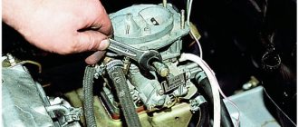
- Remove the air filter from the carburetor and the fuel hose.
- Unscrew the 5 bolts and remove the carburetor cover. Be sure to vertically so as not to damage its floats. Place this cover on a flat surface.
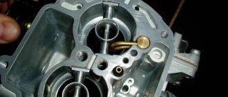
- When removing the carburetor cap, the fuel level should be at the red lines. The fuel depth must be measured. This figure should be about 29 mm. The procedure should be carried out immediately after removing the carburetor cap, since gasoline tends to evaporate.
- The height of the floats needs to be adjusted. We measure the distance from the cardboard gasket of the carburetor cover to the top of each float.
- The recommended figure is 34 mm. If necessary, you need to bend the levers and float tongue.
- Let's start adjusting the full stroke of the floats. The permissible lift of the lower angle of the float is 15 mm, and the full stroke of the float is 25 mm. Make sure that the edges of the floats are parallel to the sealing surface of the cover.
Carburetor DAAZ 4178
This device is used on some UAZ and GAZ vehicles. This series of devices, like VAZ units, performs the same function. The line of models is no different in design. Technologies that have already proven themselves are used here. The design includes float chambers with improved characteristics, as well as sequential throttle valve technology.
In general, this carburetor is built on the same base of standard parts as many others. Therefore, there is no need to consider its design in more detail.
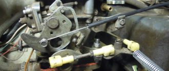
Adjusting the accelerator pump
Accelerator pump metering systems
The main task of the accelerator pump is to supply a smooth and powerful stream of gasoline through the open throttle valve of the carburetor (dripping and sluggish streams are not allowed). The stream of gasoline should enter directly into the manifold, without touching the walls of the diffuser and throttle valve.
Flowing of gasoline down the diffuser stack or throttle valve is not allowed, since the car will become very blunt and jerky when you press the gas sharply.
An accelerator pump with two spouts must be installed in different chambers. You can insert two spouts into the primary chamber - this can increase the agility of the car, but also lead to excessive “overflow”.
Settings
Adjusting the DAAZ carburetor is a complex of simple operations. To start working, you need to warm up the engine to operating temperatures. The screw that regulates the quality of the emulsion in the device should be completely unscrewed. Then it is screwed in about 2.5 turns.
A screw that allows you to adjust the amount of emulsion is necessary to adjust the number of revolutions.
If you notice a decrease in rotation speed, then you have found the transition where you can adjust the enrichment level. Now you just have to tighten the quality screw and forget about it for a long time. You were able to configure the DAAZ 4178 carburetor.
Typical faults
The DAAZ carburetor is distinguished by some typical “diseases”. To successfully configure it, you need to see and remember its problems. This device is responsible for the dynamics characteristics of the car. Therefore, malfunctions manifest themselves in the form of any problems of this nature.
If there is a problem with this device, the engine may have difficulty starting and may sneeze.
If at least one of these problems is observed, then adjustment operations need to be performed.
Adjusting the starter
The adjustment process also includes setting up the starting device.
Adjustment operations are performed with the device removed. Rotate the lever so that it closes the throttle valve. Next, you will need to turn the unit over and measure the gap between the damper and the wall. The normal size is 0.85mm.
Another gap needs to be adjusted as well. It is formed by the channel wall and the edge of the damper in its lowest part. You should close the damper and recess the trigger rod completely. The damper will be able to open, and the permissible size is from 5 to 5.4 mm. To adjust the allowable gap size, turn the adjustment screw.
Adjusting the float mechanism
The operation is carried out in three stages. First, the float is checked to ensure its correct location in relation to the walls of the chamber and its lid. This procedure makes it possible to achieve “ideal” immersion of the float by eliminating the phenomena of deformation of the bracket on which it is mounted. Deformation can be eliminated simply by straightening the fastening element with your fingers.
Secondly, close the needle valve and begin to adjust the 2107 carburetor: put the lid in a vertical position, move the float to the side, and bend the bracket tongue (using a screwdriver). All these operations are performed in order to achieve a gap between the float and the cover at a level of 6–7 mm. Thirdly, open the valve, move the float to the side, and achieve a gap of 15 mm between the needle seat and the float.
As you can see, adjusting the float cannot be considered a very difficult task. Dealing with it is not so difficult, the main thing is to be very careful and careful and not try to do everything quickly.
Adjusting idle speed
First you need to make sure that the ignition is adjusted correctly.
Then turn the quantity screw in a counterclockwise direction. Try to get the crankshaft to spin further. Have you achieved it? Now turn the quality screw until you reach even higher levels.
The point of all this is the minimum quality of the fuel emulsion, but so that the idle speed is from 850 to 900.
This is how the DAAZ carburetor is adjusted.
Carburetor engines of the open joint-stock company "Dimitrovgrad Automobile Unit Plant" have gained popularity among domestic car enthusiasts. Today, the use of carburetors is becoming a thing of the past, as they have been replaced by more modern injection systems. However, for all owners of cars with DAAZ carburetors, the issues of disassembling and assembling the carburetor, the possibility of independent adjustment and repair, remain relevant.
Adjusting the ignition angle
Sluggish acceleration of the car and instability of the idle speed are also often associated with incorrectly set ignition; this procedure is mainly carried out in car repair shops using special equipment. But if you wish, it’s easy to make the adjustment yourself, and without a strobe, and quite accurately:
- with the engine stopped, loosen the three nuts securing the distributor (the third fastening is located at the bottom, it is not visible from above);
- we start the car, turn the distributor-distributor clockwise (to “+”), and if the ignition was late, the idle speed will increase noticeably;
- we select the optimal position of the distributor (the operation of the internal combustion engine should be smooth, without failures), reduce the speed using the quantity screw, turn off the engine, fix the distributor-distributor with one nut for now, and check the results of the ignition adjustment on the fly.
If, under heavy load and sharp acceleration, your fingers begin to noticeably “knock” (engine detonation appears), you should move the distributor a little to “minus”, then check the car again while driving. This way you can set the ignition quite accurately, and sometimes even better than with a strobe light.
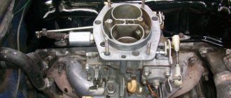
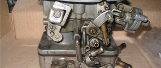
DAAZ 2107 carburetor design
A carburetor produced by DAAZ is installed on some models of Zhiguli cars. In particular, on VAZ 2105, VAZ 2107, Oda, Moskvich, etc.
Carburetors for equipping vehicles are produced here
The unit has two internal combustion chambers that operate sequentially, depending on the opening/closing of the throttle valves. The carburetor structure is determined by the following components:
- first and second chambers;
- fuel mixture dosing systems;
- idle system;
- fuel pump;
- econostat;
- motor starting device;
- economizer (forced idle).
Each of these elements is responsible for a specific area of work:
- dosing systems supply the required amount of fuel to the engine in a timely manner to ensure smooth engine starting;
- The idle system supports the operation of the carburetor power unit when driving at minimum speed or when parked;
- the pumping mechanism ensures a sharp supply of fuel to the cylinders if the road situation requires it (acceleration, overtaking, sudden starting from a standstill);
- The econostat as a device is designed to enrich the air-fuel mixture at maximum engine load;
- The economizer controls the moment of shutting off the fuel supply through the idle system.
The carburetor is equipped with many small elements.
Principle of operation
The DAAZ 2107 carburetor operates in various modes. Depending on the operating mode, certain system components will be used:
Starting the engine “cold”. The procedure is carried out by enriching the air-fuel mixture, which comes from the dosing system. At the same time, the position of the air damper is adjusted to create the necessary air flow into the chamber.
Idling. After the propulsion system warms up, the air damper closes, leaving only the necessary gap for air to enter the combustion chamber of the mixture. In this mode, gasoline is actively transferred from one jet to another, which ensures constant fuel pressure in the engine. The engine will be ready to increase speed at any time.
Medium loads. As the throttle valve opens, the air-fuel mixture is supplied to the second chamber. This reduces the fuel pressure in the system, due to which the engine produces the necessary power to move the car.
Increased loads. In this mode, all components of the motor operate. The pump operates at an accelerated pace to provide the required amount of fuel to the engine. The air damper continuously draws in air for an optimal ratio of the components of the combustible mixture.
Freddy-V8 › Blog › Carburetor adjustment Ozone 2105 and 2107 (modified 07/19/2018)
08/16/2015
Hello everyone!
This post will provide recommendations for setting up the Ozone 2105 and 2107 carburetor for normal operation. The overall success of carburetor tuning lies in the identified serviceability of the associated engine systems. These systems include spark plugs, ignition coil, distributor contacts or hall sensor and switch, phases and clearances in the gas distribution mechanism. The carburetor itself must be technically in good working order. If there is a blockage in the carburetor channels or another factor affecting its proper operation, then it is not recommended to proceed with adjustments. Our tuning example includes a completely washed and blown carburetor, but with incorrect settings of the jets, positions of the adjusting screws and float.
Adjusting the float
Remove the top carburetor cover and place it in a horizontal position with the float up. Measure the gap between the float and the carburetor gasket. The gap should be 4.5 mm. Place the carburetor cover in a horizontal position with the float down.
Measure the gap between the float and the carburetor gasket. The gap should be 12.5 mm. The float stroke should be 8 mm. The distance from the gasket to the bottom edge of the float should not be greater than the depth of the float chamber. The float must not touch the bottom of the float chamber. Adjustment of the float stroke is carried out by its two stops by bending them. Setting the initial position of the throttle valve 1 of the chamber
Screw in the throttle stop screw until the screw begins to touch the throttle stop lever.
After touching the screw, turn the screw 90 degrees clockwise. When tested against light, a thin ring of light should be visible. Setting the initial position of the throttle valve 2.
Screw in the throttle stop screw until the screw begins to touch the throttle stop lever.
After touching the screw, turn the screw 0.5 - 1 degree clockwise so that the screw supports the damper lever, but does not open it. The groove for the screwdriver on the screw must be aligned with the mark on the screw seat. When checking for light, the light ring should not be visible. Adjusting the fuel quantity screw
Adjusting the additional air supply screw
Adjusting the EPHH valve
The EPHH valve must be screwed into the mounting hole until the EPHH nozzle touches the limiter.
This moment can be determined by lubricating the rubber ring with oil and observing the contact of the ring with the mounting hole. The valve must not be overtightened. An overtightened valve may become faulty. Adjusting the carburetor with the engine running
Start the engine.
Adjust the operating speed of the crankshaft using the quantity screw and increase it by 200-400 rpm. Set the position of the throttle valve of the first chamber with the stop screw, by turning the screw 90 degrees counterclockwise, so that the engine does not stall, but runs at a minimum number of revolutions. The groove for the screwdriver on the screw must be aligned with the mark on the screw seat. Adjust the number of revolutions with the quantity screw to 800-850 rpm. Setting the idle speed without instruments
- Use the quantity screw to set the idle speed to 850 rpm.
— Use the quality screw to set the maximum speed to XX. — Use the quantity screw to raise the speed by 100-120 rpm. — Use the quality screw to lower the speed to 850 rpm. By adjusting, you achieve smooth engine operation without shaking or popping in the muffler. Setting the idle speed using the IKS-1 device (instructions for the device)
Start the engine, set the mirror in a position convenient for observation, and use the quantity screw to set the minimum stable engine crankshaft speed. Using a mirror, observe the flame in the cylinder, the color of which depends on the composition of the working mixture. - Slowly turn out the mixture screw until a bright orange flame appears, indicating an overly rich mixture. — Slowly screw in the mixture quality screw until the orange flame disappears and a bright blue flame appears, indicating a normal mixture composition that ensures the best engine performance. — Turn the mixture quality screw another 1/2+1/4 turn and complete the adjustment. To avoid failure of the IKS-1 spark plug, it is forbidden to run the engine at high idle speeds (more than 1200 rpm).
After all the carburetor adjustments, the car should drive without dips or blockages throughout the entire crankshaft speed range, providing maximum power from a healthy engine.
To more accurately adjust the CO level, use the table
09/10/2017
Adjusting the suction damper drive.
07/19/2018
My settings of the OZON-2105 carburetor
All settings are in question, since replacing the UN spout gives a faster access to the maximum speed on the ground. — GTZH 1k — 135. — GVZH 1k — 170. — GTZH 2k — 150. — GVZH 2k — 150. — Spout UN — 5.0. — ZHKH 1k — 6.0. - quantity screw - length 2cm (2 turns). — quality screw — 1 turn (deflection of the screw in any direction reduces the speed). - extra screw air supply - tightened. - float gap - 4.5mm (fuel level above the step). — according to the ICS, fuel combustion is normal (blue flame). — OZ — 8-10 degrees. — spark plug gap — 1mm.
If the carburetor settings provide faster acceleration to 100 km/h, then after that the acceleration drops significantly, almost to zero. If the settings provide stable acceleration after 100 km/h, then acceleration from a standstill turns out to be slower. Apparently, as long as there is no strong air resistance, the fuel burns more efficiently, but with an increase in drag, the fuel burns very poorly, because the carburetor begins to overflow.
Repairing the DAAZ 2107 carburetor yourself
Usually, when it comes to repairing the power unit and its components, car owners prefer to contact specialized service centers. However, the design of the DAAZ carburetor is simple both in design and in routine maintenance. Therefore, in most cases, the owner can perform basic repair work on the carburetor of his car himself.
DAAZ carburetor assembly
How to determine a carburetor malfunction
Depending on the external manifestations of engine operation, it is possible to identify problems that prevent the carburetor from fully performing its functions:
The engine cannot idle, stalls (or extremely unstable engine operation is observed).
The power unit operates normally in idle mode, but the car accelerates very slowly.
When driving above 90 km/h, there is a sharp decrease in engine power or jerking when trying to accelerate.
It is impossible to start the engine “cold”.
The engine cannot be started on the first try.
Fuel consumption while driving has increased significantly.
Thus, if the DAAZ carburetor begins to show one or more signs of these malfunctions, everything indicates that it is necessary to carry out repair work on the mechanism.
As a rule, all these signs are easily identified even by inexperienced drivers, since this does not require special equipment or specific knowledge. You can determine carburetor malfunctions based on your own sensations from driving and operating the car.
Fuel mixture quality adjustment screw Solex 21083
Why do you need a Solex 21083 carburetor quality screw?
The quality screw is necessary to change the composition of the fuel mixture entering the car engine at idle (idle). By turning the screw we lean the fuel mixture, by turning it away we enrich it. In this way, you can adjust the air/gasoline ratio to ensure it operates at a minimum stable idle speed.
Where is the quality screw installed on the Solex 21083 carburetor?
The fuel mixture quality adjustment screw is installed in the lower part of the carburetor body, at the outlet of the emulsion channel. The screw is screwed into a special channel at the bottom of the carburetor body. It changes the flow area of the outlet.
The outlet of the CXX Solex 21083 through which the fuel mixture is sprayed, the composition of which is regulated by a quality screw.
How does a Solex 21083 quality screw work?
The Solex 21083 carburetor quality screw is a metal screw of a certain shape with a thread. A rubber O-ring is installed on it to prevent excess air from entering the CXX channel. One end of the screw has the shape of a needle; the other has a cut for a 3 mm slotted screwdriver. See photo at the beginning of the article.
How does the fuel mixture quality adjustment screw work?
The easiest way to see how the quality screw works is in the Solex 21083 CXX diagram.
Under the number “14” is the quality screw.
A mixture of air and gasoline (fuel emulsion) is formed at the CXX fuel nozzle, where gasoline entering the carburetor CXX from the float chamber and air from the air duct are mixed. Under the influence of vacuum at the edge of the throttle valve of the first chamber, it is pulled through the emulsion channel and the CXX outlet into the engine intake manifold. The engine runs on this fuel mixture.
If we tighten the quality screw all the way, we will completely block the outlet of the emulsion channel of the idle system. Fuel stops flowing into the engine and it stalls.
If you turn the quality screw out a little, fuel will begin to flow into the engine and it will idle.
In order for the car engine to operate stably at idle, you should unscrew the quality screw at least half a turn from the stop and adjust the idle speed with setting the position of the fuel mixture quantity screw. It is necessary to achieve such a mutual position of these two screws that the idle speed is 650-700 rpm and the CO content in the exhaust gases is within normal limits.
Malfunction of the fuel mixture quality screw
There are only two malfunctions: clogging of the idle air system outlet and damage to the rubber O-ring on the screw.
Over time, the idle air system outlet becomes clogged with deposits and soot from the engine intake manifold. The quality screw needle ceases to play the role of a locking device, since the hole is already clogged. Depending on the degree of contamination, the engine begins to idle unsteadily or the idle speed disappears altogether. When turning the quality screw when adjusting the XX speed, the reaction will be weak or not at all.
You can quickly clean the outlet, quality screw and emulsion channel yourself without disassembling the carburetor using a cleaning aerosol. Details about the cleaning procedure: “Cleaning the idle system of the Solex carburetor 2108, 21081, 21083.”
The channel where the quality screw is installed leads directly to the CXX emulsion channel and its outlet. Therefore, this is one of the places where foreign air is likely to “suck” into the carburetor. Foreign air depletes the fuel mixture, as a result of which the engine does not have enough energy to rotate the crankshaft at idle, and it begins to “triple” and tries to stall. The reason for the air leak is a worn rubber o-ring on the quality screw. It may fail due to age or careless repairs.
Replacing the ring with a new one will help correct the problem of air “sucking” into the carburetor and restore normal idle speed of the car engine.
Notes and additions
If, with the quality screw fully tightened, the car engine does not stall, but continues to run, you should look for places where fuel is likely to enter the engine in addition to the carburetor idle system
Or pay attention to the position of the throttle valve of the first chamber. Perhaps it is very slightly open and in addition to the outlet hole of the CXX, underneath it there is an exit slot of the transition system of the first chamber and the fuel is drawn out of it by vacuum
The position of the throttle valve is regulated by the quantity screw, which with its tip rests on the lever on its axis.
How to remove a carburetor: step-by-step instructions
To remove the carburetor from the engine yourself, you will need a simple set of tools and preparation of the workplace. To carry out the procedure for removing the carburetor with your own hands, you must prepare in advance:
3 mm slotted screwdriver;
4 mm cross-head screwdriver;
wrench 7;
wrench 8;
socket wrench 13.
You will need to clear a place near the hood so that nothing interferes with work. To make the procedure easier, it is recommended to unscrew the screws securing the air filter box with a screwdriver and remove it. The following steps are aimed entirely at removing the carburetor:
Reassembling the carburetor in reverse order
After the carburetor has been removed, disassembled and cleaned, it must be reassembled. As owners of carburetor cars note, it is not always possible to do this correctly the first time. The fact is that the order in which certain tubes and hoses are connected is of great importance:
A new gasket is installed at the mounting location. You can install the old one, but only if it is not damaged or deformed.
The carburetor is threaded onto studs and pressed tightly against the gasket.
Using a 13mm wrench, attach four nuts to the studs one by one. After the carburetor takes a stable position at the intake manifold, the nuts are well tightened.
The end of the throttle linkage is screwed to the desired connector with a slotted screwdriver.
Next you will need to connect the ventilation hose, air flow vacuum tube and economizer.
After this, the throttle valve spring is inserted into the cavity of the first combustion chamber and fixed there using clamps.
The air damper drive rod must be screwed with a special screw.
Next, attach the fuel supply hose: it is important to secure the clamp well to the product.
Finally, the tip of the wire is connected, which comes from the solenoid valve.
Thus, if you follow the instructions, it is quite possible to assemble the carburetor with your own hands the first time. For new and inexperienced drivers, it is recommended to mark the hoses and tubes with different colors to make the assembly process easier.
Today, DAAZ carburetors are used less and less, as they are being replaced by more modern and efficient power units. However, the simplicity of the device and the clear operating principle of this mechanism are still popular among experienced drivers.
Setting the transient mode of carburetor operation
At idle speed, the carburetor throttle valves close and a high vacuum area is created under them, which allows gasoline to be “sucked” out of the idle channel through the nozzle. If the damper is opened sharply, the vacuum decreases sharply, which disrupts the normal operation of the main dosing system of the first chamber and a failure appears.
To eliminate these symptoms, adjust the idle jet or accelerator pump nozzles. The adjustment must be made on a warm car engine.
The idle jets or accelerator pump are changed one by one to prevent dips and delays when you press the gas sharply.
You may need to adjust the idle speed a little. Over-enrichment is not transiently displayed as black smoke coming from the exhaust pipe.
Do-it-yourself interior tuning. How to do this and what is needed for this can be found on our unique website.
From here, you can learn how to do tuning a Chevrolet Niva with your own hands.
In this informative article, you will learn how to polish a windshield with your own hands.
It is recommended to install an accelerator pump with 40x40 nozzles, and an idle nozzle with parameters from 35 to 40. If there are dips from a lean mixture and it is not possible to adjust the idle speed due to the idle nozzle being too large, then both accelerator pump nozzles can be placed in the first camera as shown in the picture.