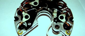
A generator diode bridge is present exclusively in “on-board power plants” of alternating current. Since most passenger cars are equipped with alternating current generators, a rectifier with diodes and a zener diode is present in each of them. Usually this unit is built into the generator, but there are remote diode bridges for convenient service, repair and replacement of diodes.
Rice. 1 The generator rectifier is a diode bridge with a zener diode
Selection of diodes for the rectifier bridge
The main thing they look at when choosing a diode is power.
It depends on the highest rated current generated by the generator. The higher the generator power, the more powerful the diodes. Diodes for the rectifier bridge are conventionally divided into categories: low power diodes, current 300 mA;
medium power diodes, current 300mA – 10 A;
high power diodes above 10 A.
Diodes are divided according to the type of material used, these are germanium and silicon. Most manufacturers prefer silicon diodes. The main reasons for choosing silicon diodes:
· low reverse current;
· high permissible reverse voltage up to 1500 V;
·operability of silicon diodes from -60 to +150оС
Germanium diodes have a low reverse voltage value of up to 400V. They operate in the temperature range from -60 to +85°C.
For example, to replace diodes for a Bosch generator with a 140A for a Touring Custom car. For such a generator you need 50A diodes, for example, Cargo 50A 138634 and Cargo 138635, for a 140A generator you will need 12 pieces, for an 80A generator 6 pieces.
Let's figure out why the diode bridge in a car generator burns
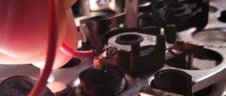
Recently the charger in the car disappeared.
The main component in the electronic system of any vehicle is the generator. Without this unit, a serviceable car, even with a new, one hundred percent charged battery, will not drive for a long time. As follows, this unit must be in working condition at all times, in other words, it must be in good working order.
With all this, initial diagnostics of the car can be carried out without leaving the driver’s seat. But repairs or a detailed check require dismantling the constant current source with its subsequent disassembly in order to open access to the diodes. But before this, the motorist must know the main methods for checking the diode bridge.
Checking the generator on a car
After installing the part in place, you need to start the car engine. Next, you need to turn on the maximum number of electrical appliances available in your vehicle (interior heater fan, wipers, car radio, interior lighting) and turn on the headlights. In this case, even at idle engine speed, the voltage in the on-board network should be 13.8 V. With this indicator, operating the car will not cause any problems.
So, we found out how to change the generator on a Gazelle.
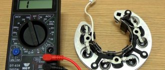
Diagnostics of a diode bridge using a multimeter
DIY xenon ignition unit repair. Possible breakdowns. Replacing the block
Before you understand why the diode bridge may be burning, you first need to dismantle the broken unit. After which a sound indication is installed on the measuring device. If such a function is not provided in the multimeter, then the test takes place in 1 kOhm mode. Individual measurements are carried out for all diodes. In the process of checking with the working contact, you need to touch the ends of the diode several times, while swapping the probes of the device. In one case, the test shows an infinitely high resistance, and in the second, the parameters should fluctuate in the range from 500 to 700 Ohms. If the measurement results turn out to be the same in different directions, this indicates that the diode under test has failed and needs to be replaced.
Diagnostics
Replacing the diode bridge of the generator on a VAZ 2112.
A often burnt-out diode bridge of the generator creates many problems. Because of this, the battery does not receive the required amount of current or, on the contrary, it receives much more of it than it should, and overcharging occurs. Before replacing this component of the generator, it is advisable to carry out proper diagnostics.
Diode bridge diagnostics
Note. It is important to know that alternator rectifier diodes are like a one-way valve that allows charge to flow in only one direction. Thus, the access of current from the on-board network to the starter windings is closed.
- If a semiconductor diode conducts current in both directions or does not conduct charge at all, then it is faulty.
- The cause of diode burnout may be moisture or improper battery charging in the winter.
Check algorithm
Replacing the diode bridge on a VAZ 2112 generator.
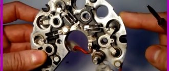
We remove the diode bridge to carry out the test - this is extremely important. How to do this will be described in detail below:
Generator rectifier block
- Take a multimeter and set it to diode test mode.
- First, we connect the plus probe to the common bus of auxiliary diodes. As for the negative terminal, it should be connected to the terminal of the diode being tested.
- The result will be positive (implying the health of the diode) if the device readings tend to infinity.
- Now you need to swap the probes. If the diode is working properly, the multimeter readings will show several hundred ohms.
Note. In the same manner we check two additional diodes of the unit.
- The minus probe is placed on the plate of the diode bridge, in the place where the diode is pressed in. The positive probe should go to the diode terminal.
- The result can be called positive if the diode does not allow charge to pass through, and the multimeter readings tend to infinity.
- Again we swap the probes.
- A positive result if the device shows a resistance of several hundred ohms.
VAZ 2112 diode bridge generator
Note. The remaining power diodes are checked in the same way.
Design features
- In the factory version, diode bridges for the VAZ 2110 are monolithic structures that are distinguished by their reliability, affordability, and compact size;
- The factory diode bridge has only one significant drawback - if one diode burns out, it is not possible to replace one element. You have to buy a new factory rectifier and replace it with the old one;
- If the diode bridge fails, you can try to assemble it yourself from different diodes;
- In the factory version, the rectifier has 4 or 6 diodes, and if you manufacture it yourself, you can add one additional one. Many people do this;
- When installing an additional diode, they do not use factory elements, but more powerful ones. This allows them to not burn out for a longer period of time.
Pinout of Lada Priora comfort block
It is difficult to check the quality of operation of a homemade rectifier, which is why interfering with the factory design can only harm the generator. Then, instead of buying cheap consumables, you will have to change almost the entire assembly.
Location on generator
Signs of diode failure
The main problem in a rectifier bridge is the diodes. You should start checking the unit that generates electricity in the car only after identifying the following indirect problems:
- the voltage at the generator output terminals is below 13.5 Volts;
- the indicator on the instrument panel inside the car continues to light after starting the power unit;
- the arrow on the voltmeter shifts to the red zone when readings are taken;
- The battery indicator does not light up after turning on the ignition.
Similar symptoms are detected when the voltage regulator breaks down; therefore, its serviceability is checked first. There are various reasons why a rectifier bridge fails, which requires its repair or complete replacement.
Symptoms of a problem
The block is equipped with 6 diodes. Failure of even one of them “guarantees” the formation of voltage dips, which begin to deviate from the norm. At the same time, electromagnetic interference is generated. How to determine that the diode bridge of the generator is not working? Main symptoms:
- rapid discharge of the battery (the corresponding lamp on the dashboard flashes or stays on after the engine starts);
- the battery is recharged, leading to boiling off of the electrolyte;
- when driving, the headlights shine dimly;
- The power of the cabin “stove” and air conditioning is clearly not enough;
- The media system operates with distortion.
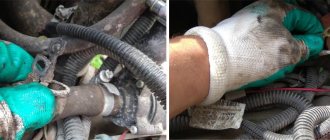
Failure of the diode bridge most often occurs due to water getting inside the generator (do not recklessly force deep puddles!). There is also a possible reason such as incorrect connection of the plus and minus when starting the engine using the “lighting” method.
Purpose of the rectifier
Since alternating current generators are more advanced, compact and repairable compared to direct current modifications, a generator diode bridge is added to the design by default to convert alternating current to direct current.
Rice. 2 Connection diagram of the diode block
In other words, without a rectifier assembly, electricity will be generated by the generator windings, but will become unusable for the on-board network and battery. Headlight lamps, air conditioning compressor windings and electrical circuits of other consumers will burn out, and the engine will not be able to start.
Rectifier block
| Control and signaling panel for the filter unit ARS-250 (400.| Boost-rectifier unit with high-voltage switchgear. |
The rectifier unit is assembled from selenium rectifiers using a single-phase bridge circuit, each arm of which consists of 39 blocks of 70 rectifier washers with a diameter of 30 mm with a permissible voltage of 20 V and a current of 300 mA. The high-voltage switchgear (RU-80), designed for a voltage of 80 kV and a load current of up to 1000 mA, is intended for connecting high-voltage circuits of an electrostatic precipitator. The device body is mounted on the cover of the boost-rectifier unit.
The rectifier unit and transformer are cooled by a fan.
The rectifier unit consists of a transformer with a 110 V primary winding and a selenium rectifier composed of several groups of selenium washers.
| Tractor valve generator. / – regulator block. 2 – stator. 3-rotor. 4-excitation winding. 5 – rectifier block. |
The rectifier unit of a tractor VG with a power of 1 kW or more is fixed on the rear cover and cooled by its own centrifugal fan mounted on the generator shaft.
The rectifier unit, just like a car VG, is fixed in the internal cavity of the generator, and the voltage regulator is on its back cover.
The rectifier block (see Fig. 2.2, block 7) is the main power source for the current circuit of the measuring circuit. It is a full-wave selenium rectifier and consists of a transformer, a selenium column, a U-shaped filter and a switch at the output of the rectifier. The primary winding of the rectifier transformer unit is supplied with a current of 220 V from the ferroresonant stabilizer SNE-05-220.
The rectifier unit includes three monoblocks connected into a full-wave three-phase rectifier circuit. Each monoblock, which is both a radiator and a conductive midpoint clamp, contains two semiconductor silicon washers.
The rectifier unit is designed to control the incandescence of emitters 13, 27 and supply the voltage to the stabilization unit.
The rectifier unit is made according to a three-phase bridge circuit. Due to the presence of a rectifier unit and the supply of constant voltage to the generator lamps, the efficiency of the installation increases.
Rectifier unit 2, mounted in the cover /, differs from traditional ones in that three additional direct conduction diodes are mounted in it (see diagram in Fig. 2.18), through which the excitation winding is powered from the generator. The rectified voltage from the additional diodes is supplied to plug terminal 10, designated pin 61 in the diagrams, and by a conductor to plug terminal / / of voltage regulator 12, which is marked V.
The rectifier unit is made according to a three-phase bridge circuit and consists of three parallel-connected selenium columns with plates measuring 100xx400 mm.
The rectifier unit consists of two rectifiers assembled in a bridge circuit on diodes 6 and 7 (D7Zh) with U-shaped inductor-capacitor filters and electronic voltage stabilizers.
The 1000 A rectifier unit consists of six valve arms. The rectifier unit is made in the form of a cabinet with double-sided doors. The cabinet contains 36 valves with coolers.
Main signs indicating a faulty diode bridge
A normally operating diode conducts current in only one direction. In the event of a breakdown, a current leak appears, which flows from the on-board network to the starter windings. Today, several types of diode bridges are installed on cars:
- diode bridge without additional cooling;
- diode bridge with passive cooling due to special radiators.
In addition, there are different types of connecting windings and connecting bridge platforms: using welding or soldering. The first sign that the generator is operating unstably due to a broken diode bridge is the rapid and frequent discharge of the battery. There are other reasons why you can indirectly determine the combustion of diodes in a rectifier:
- insufficient spark on the spark plugs;
- headlights with dim light during operation of the power unit;
- interruptions in the sound system;
- significant reduction in cooling fan power;
- poor operation of the air conditioning system.
If any of the above-mentioned signs are noticed, there is no need to panic, but it is better to find out why the diodes burned out, for which you should seek help from the service station specialists.
How to remove the generator on a Gazelle?
Now let's consider the issue of dismantling. When carrying out repair operations on a Gazelle car, removal of the generator must be carried out in accordance with all technological instructions and follow safety rules when carrying out work. If the car engine is hot, you need to let it cool down to avoid the possibility of getting burned.
If there is a malfunction of the generator, it is removed from the car engine and diagnostic and repair operations are carried out. To do this, you can contact service workshops or carry out repairs yourself. Many car enthusiasts who encountered this problem for the first time are wondering how to change the generator on a Gazelle. The operation of removing and installing this part is not a complex technological or repair process, and can be done at home. To do this you will need a standard set of tools.
Technical characteristics of the generator 9402.3701
| Maximum output current (at 13 V and 6000 min-1), A | 80 |
| Voltage, V | 13,2–14,7 |
| Direction of rotation (drive side) | right |
The stator and generator covers are secured with four screws. The rotor shaft rotates in bearings installed in the covers. The lubricant placed in the bearings at the factory is designed to last the entire service life of the generator. The rear bearing of the generator 9402.3701 is pressed onto the rotor shaft and is pressed by the rear cover through a plastic sleeve, the front bearing is pressed and rolled into the front cover and can only be replaced together with it. Its inner race, together with the thrust ring and washer, is clamped by a nut between the pulley and the step on the rotor shaft. The front bearing of the generator 37.3701 is secured with four screws between the inner and outer washers and can be replaced separately from the front cover. The rear part of the generator 9402.3701 is closed with a plastic casing with latches.
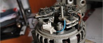
The generator stator contains a three-phase winding made in a star configuration (the terminals of the phase windings have a common point). The second ends of the phase windings are connected to a rectifier bridge consisting of six silicon diodes (valves) - three “positive” and three “negative”. The valves are pressed into two horseshoe-shaped aluminum holder plates in accordance with the polarity (positive and negative - on different plates); one of the plates also contains three additional diodes, through which the excitation winding of the generator is powered after starting the engine. The plates are combined into a rectifier unit mounted on the rear cover of the generator (under the plastic casing of the generator 9402.3701).
The excitation winding is located on the generator rotor, its leads are soldered to two copper slip rings on the rotor shaft.
Power is supplied to the field winding through two brushes. Alternator slip rings (9402.3701) have a reduced diameter to reduce peripheral speed and reduce brush wear. The brush holder is structurally combined with the voltage regulator and is mounted on the back cover of the generator. The voltage regulator is non-separable; if it fails, it is replaced.
Until 1996, for the 37.3701 generator, the brush holder and voltage regulator were separate units (voltage from terminal “30” of the generator was supplied to terminal “B” of the voltage regulator). Now voltage is supplied only to terminal “B” (terminal “B” is missing). According to their characteristics, the new and old voltage regulators are the same and, when assembled with a brush holder, are interchangeable.
To protect the on-board network from voltage surges during operation of the ignition system and reduce interference with radio reception, a capacitor with a capacity of 2.2 ±0.04 μF is connected between the terminals of the “positive” and “negative” valves (between the “+” and “ground” of the generator), located on generator rectifier block 9402.3701 and generator rear cover 37.3701.
When the ignition is turned on, voltage is supplied to the excitation winding of the generator (terminal “D” of generator 9402.3701 and “B” of generator 37.3701) through a control lamp in the instrument cluster (the lamp is lit) and resistors connected in parallel to it. After starting the engine, the excitation winding is powered by additional diodes of the rectifier unit (the control lamp goes out). If the lamp lights up after starting the engine, this indicates a malfunction of the generator or its circuits.
The “minus” of the battery should always be connected to the “ground” of the car, and the “plus” to the “B+” terminal of the generator 9402.3701 (“30” of the generator 37.3701). Switching back on will lead to breakdown of the generator valves.
It is not recommended to disconnect the battery when the generator is running (especially on engines equipped with an injection system). The resulting voltage surges in the on-board network can damage the electronic components of the circuit.
The generator valves (and other devices in the vehicle’s on-board network when the generator is connected) should be checked at a voltage no higher than 15 V; a higher voltage (for example, when checking with a megger) can cause damage to the valves.
If it is necessary to check the insulation of windings with high voltage, the generator should be removed, and the winding terminals should be disconnected from the rectifier unit and voltage regulator
Checking the condition of parts
Regardless of which generator is installed on the Gazelle, the causes of the malfunction, as a rule, can be of the same nature.
The generator brushes should not have chips or cracks; when pressed with a finger, they should freely sink into the channels of the brush holder, and return to their original position under the influence of the spring.
The length of the brushes should not be less than 4 mm, and if there is severe wear, they are replaced with new ones.
The stator is checked for short circuits between the turn windings and the housing.
This is done by connecting one terminal of the control light to the housing, and the second is alternately connected to one of the three terminals of the turns. In this case, if there is a short circuit to the housing, the indicator light will light up. Having discovered this type of malfunction, it is eliminated or the stator is completely replaced.
To check the stator for a short circuit between the turns, a test lamp is alternately connected to the two terminals of the windings. Moreover, if the light bulb lights up, then there is no break in the turns.
The generator rectifier unit should be cleaned of dust and dirt deposits. Next, you should check the diodes using a test lamp. Due to the fact that diodes of different polarities are placed in each section, they are checked with different battery connection polarities. If a faulty diode is detected, the rectifier unit is replaced.
Schemes of rectifier blocks for automobile generators.
In rectifier blocks of domestic automobile generators, diodes D104-20, D104-25, D104-35 are usually used, designed, respectively, for maximum permissible currents of 20, 25, 35 A. In three-phase generators, the maximum generator current should not exceed triple the maximum permissible current through diode. So, if diodes are used with a maximum permissible current of 20 A, then when using a rectifier bridge with six such diodes, the maximum generator current cannot exceed 60 A. If a generator with a higher current is required, then you can use a rectifier unit with diodes for a higher maximum permissible current or a rectifier unit with twelve diodes.
Figure 8.1 – Diagram of a rectifier unit with twelve diodes.
It should be noted that doubling the generator current when doubling the number of diodes does not occur, since the current is distributed unevenly between two parallel diodes. From the rectifier unit shown in Figure 8.1 with 20 A diodes, you can get a current of 90-100 A. In order to provide a larger generator output current, you can increase the number of stator winding phases. The number of phases is chosen odd, for example 5,7,9 and so on. When using an even number of phases, the number of rectified voltage ripples decreases by 2 times compared to an odd number of phases, and their amplitude increases, which negatively affects the quality of the generator output voltage.
On special vehicles, a five-phase generator is used with a five-phase main rectifier bridge and a three-phase additional rectifier to power the field winding.
The currents in the field winding are small, so it is not advisable to use a five-phase rectifier. To power the excitation winding, a three-phase rectifier bridge is used, connected so that the voltage at its output is maximum.
Modern generators sometimes use three-phase rectifier bridges with 4 arms.
The fourth arm is connected by input to the neutral of the stator winding and is used to rectify higher harmonics. The fact is that in a real generator the shape of the phase voltage differs from the sinusoid. It represents the sum of harmonics - the first, the frequency of which coincides with the frequency of the phase voltage, and the highest, for three-phase generators, mainly the third.
Figure 8.2 – Diagram of a rectifier block for a generator with five phases and an additional rectifier.
Figure 8.3 – Features of the operation of a rectifier with an additional arm.
A shift of 120° between the phases of the generator for the first harmonic corresponds to a shift of 360° for the third harmonic, 720° for the sixth harmonic, and so on for harmonics that are multiples of three. Therefore, third harmonics and harmonics that are multiples of three different phases of a three-phase generator have vectors directed equally (Uф1mг and Uф2mг in Figure 8.3, a). In linear voltages, which are the vector sum of two phase voltages, harmonics that are multiples of three are destroyed (Ul = Ul').
Figure 8.4 – Phase voltage as the sum of sinusoids of the first and third harmonics.
A conventional rectifier does not rectify third harmonics as it rectifies line voltage.
In order to use the power developed by the third harmonic, an additional arm is added to the rectifier. This arm is connected to the neutral point of the stator winding (see Figure 5.8, b). Thus, phase voltages are supplied to the input of the rectifier unit, which contain harmonics that are multiples of three. Therefore, the rectifier shown in Figure 5.8b additionally rectifies harmonics that are multiples of three. The use of an additional arm increases the generator power by 5–15%.
Expensive cars are equipped with complex electronics that are very sensitive to overvoltages. To get rid of overvoltages, instead of diodes in the rectifier block, zener diodes are used, the stabilization voltage of which is 1.5 times greater than the generator voltage.
Figure 8.5 – Diagram of a rectifier bridge using zener diodes.
If the instantaneous voltage value at the generator output exceeds three times the rated voltage of the generator, the zener diodes will break through and load the generator with additional current, which will lead to a decrease in the pulse amplitude of the generator output voltage.
How to replace a diode bridge yourself Detailed instructions
- a screwdriver with a ratchet, for a set of various bits;
- 8 mm head;
- extension rod.
- 1. The first step is to remove the terminals from the battery;
- 2. Remove the wires going to the charger;
- 3. Remove the generator block, marked with the letter “D”;
- 4. Remove the plastic cover from the positive charge wires. Unscrew the bolts and disconnect the wires;
- 5. Then remove the casing on the generator body (black). To do this, you need to unclip several fasteners around the circumference of the casing;
- 6. Now comes the dismantling of the device. Unscrew it and remove it;
- 7. Remove the regulator complete with brushes;
- 8. This is where the diode bridge is located. Use a socket or an 8 mm open-end wrench to unscrew it (fastened with 3 bolts);
- 9. Next, we bend several wire outputs to the starter winding, and also bend the capacitor fasteners;
- 10. Then we take out the diode bridge. Unscrew several 10 mm nuts. We take out the bushings from the contact bolt. Now remove the contact bolt from the diode device.
AutoFlit.ru
Disassembly
This section describes a step-by-step process that will help you correctly disassemble the Gazelle generator.
So, first you need to remove the plastic protective cover from the case. Then unscrew the brush block and the voltage regulator, having first disconnected the wiring from it. Next, you should unscrew the four tie rods of the generator housing and remove the housing cover together with the stator. Then, having disconnected the winding terminals from the diode bridge, you need to remove the stator, and, if necessary, the diode bridge itself.
Next, remove the drive pulley and the cover with the rotor bearing from the shaft.
You can carry out the process of diagnosing generator parts using measuring instruments: E236 or a special test light.
Causes of malfunctions
The practice of motorists shows that replacing a diode bridge can be caused by various reasons, but the main one is still a feature of factory production.
Therefore, let's take a closer look at the reasons for rectifier failure, which may lead to the need to replace the device.
| Cause | Peculiarities |
| Factory version | Many manufacturers use aluminum shells for diodes, which are not of high quality and reliability. It is recommended to choose steel shells. The experience of specialists and motorists shows that the best rectifiers today are made in Belarus |
| Moisture | Moisture can penetrate inside the structure and lead to oxidation of the space between the housing and the diodes |
| Oil | Oil also leads to disruption of the functionality of the device if it penetrates inside the generator structure and specifically onto the diode bridge |
| Battery polarity confusion | If, when connecting a battery to a charger or when lighting a cigarette, you accidentally reverse the polarity, this will most likely lead to a breakdown or burnout of the bridge |
| Weak battery | If the battery does not hold power and constantly has a weak charge, the rectifier may be the culprit |
Before you start replacing the device, you must first check the generator and bridge, thereby making sure that the rectifier is the culprit of the problem.
Advantages of a factory rectifier
Many people believe that when repairing a car it is better to use analog spare parts, which are more expensive but of higher quality. This is a fair statement for many spare parts, to be sure.
But if we are talking about a rectifier, then for a VAZ 2110 when replacing it is better to use the factory version, that is, a monolithic diode bridge.
This is explained by several important advantages. Namely:
- Affordable price, which allows you to perform inexpensive repairs yourself;
- Small size, compact device;
- The diodes used interact effectively with each other, their parameters match optimally;
- Due to the high-quality arrangement of diodes, the bridge operates in a single heating mode. This, in turn, allows you to avoid overheating with a high degree of probability;
- Easy to replace and install. The procedure is easy, which allows you to do the repair yourself.
Do-it-yourself removal and disassembly of a VAZ generator
| Generator 2110 is a part without which the operation of the car is impossible. Its condition must be checked every maintenance (15 thousand km). If during the diagnostic process of the generator, comments were identified, they must be addressed urgently. Let's look at how to remove the generator yourself, as well as disassemble it (remove the voltage regulator, diode bridge and bearings). |
Replacing the VAZ 2110 generator
- Disconnect the generator excitation wire.
- Unscrew the nut securing the wires to terminal “B+” using a “10” wrench.
- Remove the “B+” terminal wires.
- Remove the generator tension bar.
- Unscrew the nut of the lower mounting of the generator using a “13” wrench.
- Remove the mounting bolt.
- Remove the tens generator.
Removing the generator voltage regulator
- Release the 3 spring clips and remove the protective cover of the generator diode bridge.
- Unscrew the 2 screws securing the voltage regulator using a Phillips screwdriver.
- Disconnect the block with the wire from the output of the relay-regulator and remove it.
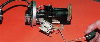
Removing the diode bridge from the generator
- Unscrew the 3 bolts that connect the terminals of the stator windings to the rectifier block (1) using an “8” spanner, and 1 more bolt holding the diode bridge (2). Remember how the isolating and thrust washers are installed.
- Bend the wires of the stator winding leads to the side.
- Unscrew the capacitor mounting screw using a Phillips screwdriver.
- Remove the diode bridge along with the capacitor. Unscrew the 2 contact bolt nuts using a 10mm socket wrench. Remove the spacer and insulating bushings from the bolt, remove the bolt from the diode bridge and the capacitor tip from the contact bolt.
Replacing the front and rear bearings of the generator
- Before removing the front and rear covers of the generator, you should mark their location with a marker.
- Unscrew the 4 bolts using an “8” socket wrench.
- Open the generator covers using a flathead screwdriver.
- Disconnect the back cover from the front along with the stator winding.
- To remove the front bearing of the generator, you need to attach a suitable object to it, for example, a “27” socket. Then knock it out with hammer blows.
- Lubricate the bearing seat.
- The front bearing is installed using the old one. Place it on top and carefully drive the bearing in a circle.
- The front generator bearing is installed.
- If a special puller is not available, then a large open-end wrench will be required. We pick up the rear bearing with a wrench, as shown in the photo.
- Lightly hit the key with a hammer and move it around in a circle to remove the rear bearing of the generator.
- The rear bearing has been removed from the generator rotor shaft.
- Installation of the rear bearing can be done using a piece of pipe of a suitable diameter (for example, a deep “19” socket). Using light blows of a hammer, press the new bearing onto the generator rotor shaft.
xn--2111-43da1a8c.xn--p1ai
More details about replacement
Of course, this procedure can easily be performed by a technician at the nearest service station. However, many car enthusiasts prefer to repair or change parts on their car themselves. If you have knowledge and experience in this matter, then follow this algorithm:
- At the very beginning, you should turn off the power to the VAZ-2110.
- Next you need to disconnect the battery.
- Then pull out the pink wire that turns on the generator. To do this, unscrew the nut from the positive bolt.
- Then you need to loosen the upper and lower nuts and remove the tension bolt. After all this, you need to remove the belt.
- Next, the generator is turned 90 degrees, removing the lower mounting bolt.
- Then all connections need to be cleaned, including the rectifier housing.
- The upper part must be cleaned especially carefully.
- After this, the mechanism is replaced, and all connections are assembled in the reverse order.
- Finally, you need to check how the generator works.
When purchasing a new mechanism, you need to know that it must come with a warranty card. That is why you should buy only in specialized stores. If you find it difficult to replace the diode bridge yourself, then it is better to entrust this work to specialists from the technical service. They will easily perform the replacement, without removing the generator and with a guarantee.
Source