“Car generators come in two types: direct and alternating current,” this phrase can be read in academic publications. In reality, a car with a DC generator today can only be found at a retro technology exhibition.
Since the 60s of the last century, alternating current generators have been installed in cars. A rectification unit is needed to convert alternating current into direct current to power automotive electrical appliances. Why it was necessary to bother so much and what significant advantages alternating current generators have is a topic for a separate article.
What is a diode bridge?
Diode bridge - a unit of a vehicle's electrical generator;
an assembly of semiconductor rectifier diodes that provides rectification of the alternating current generated by the generator. The electrical systems of cars, tractors and other vehicles mainly use three-phase alternating current generators. Such generators are simple in design, reliable and efficient, but they produce three-phase alternating current, which cannot power electrical appliances installed on the car. To obtain direct current from alternating current, generators use a diode bridge or a rectifier module.
The diode bridge is connected to the stator windings of the generator and ensures the conversion of three-phase alternating current to direct current. From the output of the diode bridge, current flows to the battery and to all consumers present in the automotive electrical system. A malfunction of this module often makes the vehicle impossible to operate. In order to properly carry out repairs, it is necessary to understand the types, designs and features of diode bridges of modern generators.
How to replace the diode bridge of a car generator with your own hands? Step-by-step instructions and correct tips
Even if the generator
alternating current built into the
electrical
of a modern car is unusable, then this immediately affects
the start of
the vehicle’s power unit.
Often, this situation arises due to problems that appear in the diode bridge
of the generator.
One of the main indicators
diode bridge
failure is
battery
discharge warning light dashboard
, which may start flashing if the generator
has stopped
recharging the battery.
According to auto experts, in most cases this symptom is directly related to a problem with the voltage regulator
or
diode bridge test
.
According to auto mechanics, replacing a diode bridge
is not a complicated procedure and is accessible to almost every car owner; the main thing in this matter is to follow
the step-by-step instructions
and listen to
the right advice
from experts.
{banner_adsensetext} Before moving on to the step-by-step instructions for checking and replacing the diode bridge, you should first find out what this generator component is. A diode bridge
is a special electronic circuit that is assembled on the basis of rectifier diodes designed to convert the alternating current supplied to it into direct current.
Thus, the diode bridge
, also known as
a rectifier unit
, performs
the function
of converting the alternating current generated in
the stator winding
of the generator into electric current with a constant voltage.
Where is the diode bridge located?
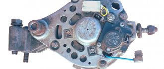
In most standard generators, a diode bridge
(rectifier unit) is installed on the rear of the generator.
Typically found in standard
37
series generators .
3701
, which are installed on many modern domestic passenger cars, for example,
VAZ
(
Lada
), the diode bridge
is attached
to
the rear wall
of this key component of electrical equipment.
{banner_reczagyand}
STEP-BY-STEP INSTRUCTIONS AND CORRECT TIPS FOR REPLACING THE GENERATOR DIODE BRIDGE 1
.
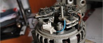
Dismantling the generator
. So, before you can be sure whether there are problems in the rectifier unit, the first step is to carry out an accurate check of the component. To do this, the generator is dismantled, and then it is taken out of the engine compartment, after which it is placed on a bench, if available.
2
.
Tester check
. After dismantling, using a special voltage tester or the simplest version of an ohmmeter, the quality of current flow through the generator circuits is tested. If, as a result of checking these readings, the fact of failure of the semiconductors is confirmed, then the diode bridge will have to be completely replaced.
3
.
Replacing the diode bridge
. If the car owner still has to change the diode bridge with his own hands or he is going to replace its individual components, then you need to be prepared for the fact that this procedure is by no means an easy one, since the operation requires from the performer not only extreme concentration, but also the presence of certain practical skills .
4
.
Preparation for dismantling the diode bridge
. To gain access to the diode mounting area, you will have to remove the brush block from the generator and unscrew the nuts that tighten the front and rear covers together. After this, you can disconnect the unit element with the pulley and rotor from the stator.
5
.
Dismantling the diode bridge
. Next, after part of the generator has been disassembled, it is necessary to unscrew the bolts securing the leads of the stator windings to the rectifier block using a socket wrench. And only when the negative wire from ground has been disconnected can you remove the middle element of the unit by disconnecting it from the back cover, from which the bolts with insulators and the diode bridge itself are then carefully removed.
6
.
Installation of a new diode bridge
. After installing a new rectifier unit instead of the old one, in the free space, the screws with insulators are screwed into the cover again. Next, the leads of the stator windings are screwed onto them again. Subsequently, the screws are finally tightened.
7
.
Assembling generator components
. The rotor along with the front cover is inserted through the stator onto the rear wall of the generator. Next, the generator housing is installed and tightened with screws.
8
.
Final assembly and installation of the generator
. And finally, at the very end of the procedure, the generator brushes are installed and the body of the entire device is checked for reliability. Next, pick up an electrical equipment tester and ring the generator. If, after ringing, no problems are found, then the generator is installed back under the hood of the car, after which the change of the diode bridge is finally completed.
For reference, we note that
the diode bridge of the generator
can be
assembled
not only from
individual
components, but also made in the form of
a monolithic
structure, like
a diode assembly
, where
the diodes
are usually selected according to
parameters
.
Such a diode bridge
is much
easier
to install and
lasts
much
longer
than usual.
According to experts, the main disadvantage
of a diode bridge is the need
to replace
the entire
assembly
, even if
only
one
fails .
Video
:
“How to replace the diode bridge of a car generator without errors? “
In conclusion, we would like to add that there are only two main failures of the diode bridge of the generator - a “break” and/or a “short circuit” of the diodes.
In the case of a “break,” the diode stops passing electric current through itself, and in the case of a “short circuit,” the current, on the contrary, flows in both directions, therefore, the diode is “broken.” In any of the cases, the car generator loses its ability to produce the required amount of electric current and a control indicator lamp lights up on the dashboard, indicating that the battery is low. THANK YOU FOR YOUR ATTENTION
.
SUBSCRIBE TO OUR NEWS
.
SHARE WITH YOUR FRIENDS
.
What you need to know about diode bridges
First, we will look at what they are and what is inside a diode bridge. These circuit elements are available in two versions:
- From discrete (separate) diodes. Usually soldered on the board and connected by tracks in the correct circuit.
- Diode assemblies. The assemblies can be either single-phase bridges for rectifying both half-cycles of alternating voltage, or assemblies of two diodes connected in a circuit by a common cathode or anode, and other connection options.
In any case, the rectifier single-phase diode bridge consists of four semiconductor diodes connected to each other in a series-parallel manner. Alternating voltage is supplied to two points at which the anode and cathode are connected (opposite poles of the diodes). Constant voltage is removed from the connection points of like poles: plus from the cathodes, minus from the anodes.
In the diagram, the connection point for alternating voltage is indicated by the symbols AC or “~”, and the outputs with constant voltage are “+” and “-“. Draw this diagram for yourself, it will be useful to us when checking.
If you imagine a real diode bridge and combine it with this circuit, you get something like:
Video: operating principle of a diode bridge
Practical use
In practice, the diode bridge has a fairly wide range of applications - this includes digital technology, power supplies in personal computers, laptops, various devices, car generators powered by low DC voltage. In addition, they can be found in sound reproduction systems, measuring equipment, television and radio broadcasting, and they are installed in a number of different devices throughout the house. To better understand the role of the diode bridge in these devices, we will look at several specific circuits in which it is used.
Examples of diode bridge circuits and their descriptions
One of the simplest circuits using a diode bridge is a charger used for equipment powered by low voltage. Let's look at one of these options using the following example:
Rice. 5. Charger circuit
As you can see in the figure, from the step-down transformer T1 the voltage from alternating 220V is converted to alternating at a level of 7 - 9V. After this, the reduced voltage is supplied to the diode bridge VD, from which it is rectified through the smoothing capacitor C1 to the KR microcircuit. The rectified voltage from the microcircuit is stabilized and supplied to the connector terminals.
Rice. 6. Flashlight diagram
The figure above shows an example of a flashlight circuit; this model is connected to a 220V household network through a socket, which is represented by connecting connectors X1 and X2. Next, the voltage is supplied to the VD bridge, and from it to the DA1 chip, which, if there is input power, signals this through the HL1 LED. After this, the power supply is supplied to the GB battery, which is charged and then used as the main power source for the flashlight lamp.
Example of a welding unit diagram
Here is an example of a welding unit circuit in which a diode bridge is installed immediately after a step-down transformer to rectify the electric current. Due to the complexity of the circuit, further consideration of the operation of the device is impractical. It is worth noting that there are other devices with an even more complex operating principle - switching power supplies, PWM modulators, converters, etc.
Causes of diode bridge failure and its symptoms
The diode bridge of the generator is structurally designed as a separate module. The forming elements may fail during ongoing operation. This happens for the following reasons:
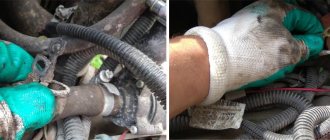
- moisture entering the electrical circuit when washing a car or engine;
- penetration of dirt and oil into the generator housing with broken seals (occurs when driving at high speed on dirt roads);
- reversing the polarity of the battery contacts while “lighting” another car.
Indirect signs of bridge failure are manifested in the fact that
- the voltage at the generator output does not exceed 13.5 V or the ammeter needle is in the red sector;
- spark power decreases;
- the brightness of the headlights changes noticeably with changes in engine speed;
- the performance of the cooling system fan decreases;
- the starter does not develop the required number of revolutions;
- the normal functioning of the on-board air conditioning is disrupted.
Symptoms of a problem
The block is equipped with 6 diodes. Failure of even one of them “guarantees” the formation of voltage dips, which begin to deviate from the norm. At the same time, electromagnetic interference is generated. How to determine that the diode bridge of the generator is not working? Main symptoms:
- rapid discharge of the battery (the corresponding lamp on the dashboard flashes or stays on after the engine starts);
- the battery is recharged, leading to boiling off of the electrolyte;
- when driving, the headlights shine dimly;
- The power of the cabin “stove” and air conditioning is clearly not enough;
- The media system operates with distortion.
Failure of the diode bridge most often occurs due to water getting inside the generator (do not recklessly force deep puddles!). There is also a possible reason such as incorrect connection of the plus and minus when starting the engine using the “lighting” method.
We are looking for a diode bridge on the board
You can check both the diode bridge installed on the board and the one soldered from it; the second option is considered more accurate, since the test is not affected by other circuit elements, but it should be remembered that some testing methods can only be implemented in a working device. If the design of the device is quite complex or the board is overcrowded with parts, it is advisable to look for a diode bridge in the following locations:
- in power supplies;
- in secondary circuits of transformers;
- at the output of generators;
- in front of the batteries.
After detecting a diode bridge, it is necessary to inspect its housing or each diode individually. An experienced electrician will automatically notice the location of the inputs, but if it is difficult for you to focus on memory, you can draw a diagram in relation to your situation. On such a diagram you need to display the positive terminal and the negative terminal, the AC voltage input terminals.
It should also be noted that the malfunction may not only lie in the diode bridges, so during the inspection it is worth carefully inspecting all elements and parts, and when checking, do not exclude the integrity of the object.
Main signs indicating a faulty diode bridge
A normally operating diode conducts current in only one direction. In the event of a breakdown, a current leak appears, which flows from the on-board network to the starter windings. Today, several types of diode bridges are installed on cars:
- diode bridge without additional cooling;
- diode bridge with passive cooling due to special radiators.
In addition, there are different types of connecting windings and connecting bridge platforms: using welding or soldering. The first sign that the generator is operating unstably due to a broken diode bridge is the rapid and frequent discharge of the battery. There are other reasons why you can indirectly determine the combustion of diodes in a rectifier:
- insufficient spark on the spark plugs;
- headlights with dim light during operation of the power unit;
- interruptions in the sound system;
- significant reduction in cooling fan power;
- poor operation of the air conditioning system.
If any of the above-mentioned signs are noticed, there is no need to panic, but it is better to find out why the diodes burned out, for which you should seek help from the service station specialists.
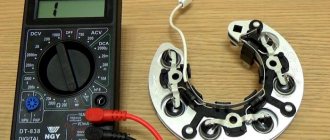
Testing the diode bridge with a multimeter
Any part on the board can be desoldered for testing or ringing without desoldering. However, the accuracy of the check in this case is reduced, because perhaps a lack of contact with the board tracks, with visible “normal” soldering, the influence of other circuit elements. This also applies to the diode bridge; you don’t have to desolder it, but it’s better and more convenient to desolder it for testing. A bridge assembled from individual diodes is quite convenient to check on the board.
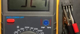
Almost every modern multimeter has a diode test mode, usually it is combined with an audio continuity test of the circuit.
This mode displays the voltage drop in millivolts between the probes. If the red probe is connected to the anode of the diode and the black probe to the cathode, this connection is called forward or conductive. In this case, the voltage drop across the PN junction of the silicon diode is in the range of 500-750 mV, which you can see in the picture. By the way, it shows a test in resistance measurement mode, this is also possible, but there is also a special diode test mode, the results will be, in principle, similar.
If you swap the probes - red to the cathode, and black to the anode, the screen will show either one or a value of more than 1000 (about 1500). Such measurements indicate that the diode is working; if the measurements differ in one of the directions, then the diode is faulty. For example, if the continuity test is triggered - the diode is broken, there are high values in both directions (as with reverse switching on) - the diode is broken.
Important!
Schottky diodes have a lower voltage drop, about 300 mV.
There is also an express check of the diode bridge with a multimeter. The procedure is as follows:
- We place probes at the input of the diode bridge (~ or AC), if the continuity test works, it is broken.
- We put the red probe on “–”, and the red one on “+” - a value of about 1000 appears on the screen, swap the probes - on the screen 1 or 0L, or another high value - the diode bridge is working. The logic of this test is that the diodes are connected in series in two branches, pay attention to the diagram, and they conduct current. If the positive power supply is applied to – (anode connection point), and the power supply minus is applied to “+” (cathode connection point), this is what happens during dialing. If one of the diodes is broken, current may flow through the other branch and you may make erroneous measurements. But if one of the diodes is broken, the voltage drop across one diode will be displayed on the screen.
The video below clearly shows how to check a diode bridge with a multimeter:
Checking the diode - how to do it right
Based on the fact that a diode is a semiconductor device that passes current only in one direction, let’s begin the test.
· The diode bridge must be removed. Diodes need to be checked individually, disconnected from the general circuit. The test must be performed in the “diode check” position.
· We touch the bottom of the diode with one of the probes, and its terminal with the other. The amount of resistance depends on the power of the semiconductor. The resistance should be in the range of 400 - 800 Ohms, that is, the diode passes current in this direction.
· Swap the probes. A unit on the multimeter screen is evidence that there is no conductivity in this direction. This means the diode is locked and intact.
· Otherwise, if the tester shows the presence of resistance (current flow) in both directions during testing, this indicates a diode malfunction.
Important to remember. When checking diodes located on the same plate, the resistance should not differ. The permissible maximum is 5 Ohms, no more. The presence of a diode with a large difference in readings indicates its poor performance and subsequent charging problems. Therefore, it is advisable to change the diode.
Checking diodes with a tester is very conditional; you can more accurately verify the integrity of the diode only under load, for example, by connecting a lamp to the circuit or on a diagnostic test bench at a service station.
Checking with an indicator screwdriver
This is the simplest test option, which will give a general idea of the condition of the diode bridge and the entire circuit as a whole. To operate, you only need an indicator; the entire procedure is performed under voltage, so extreme caution should be used:
- Touch the tip of the screwdriver to each AC voltage terminal of the diode bridge in turn. If the light does not light, this indicates a fault in the circuit up to the diode bridge - a broken winding, a broken charger, etc. If the light is on, then voltage is supplied to the bridge normally.
Rice. 2. Testing with an indicator screwdriver
- Also touch the positive terminal with a screwdriver - if the light comes on, then the diode bridge normally passes positive half-cycles, respectively, there is potential at this pin. If it does not light, there is damage to the diode bridge.
- Repeat the same procedure with the negative terminal. Be sure to divide the test into both terminals of the rectifier unit, since a fault may be present in any diode and in any branch.
As you can see, in this example an insulated blade screwdriver was used. This is due to the need to perform work under voltage, when you can cover different parts of the electrical installation with a metal part, which will entail extremely unpleasant consequences. A significant disadvantage of the method is its low information content and the limitation on the operating voltage - since the indicator is designed for a nominal value of 220 V, it cannot be used for low-voltage circuits.
Video: Diode bridge. Examination
Checking with a light bulb
To implement this method, you need a 12-volt low-power light bulb and three wires 1 meter long. Two of them are used to form the indicator cord. To do this, they are first connected to the contacts of the light bulb, which as a result ends up in their gap. The third wire connects one of the battery contacts to the bridge.
To check the circuit, the bridge body is connected to the battery negative with a third wire. Then one end of the indicator cord is connected to the negative terminal of the bridge, and the other end is connected to pin 30 of the bridge. The light coming on is a sign of a breakdown of the bridge, and its absence indicates a break.
To check the negative diodes, the minus voltage of the battery is applied to the bridge body. The plus of the battery is connected with an indicator cord to the fixing screw of the bridge. If the lamp lights up, it indicates a breakdown; its absence indicates a break. Testing positive diodes begins by applying the battery positive to terminal 30, and the negative is connected through the indicator cord to the bridge mounting screw. If the diodes are working properly, the lamp does not light up.
Something else useful for you:
How to check without dismantling
You can diagnose the device on site without disassembling the generator or desoldering the part. To do this, unscrew all the wires on the generator and voltage regulator, set the tester to ohmmeter mode, and connect the lamp to the battery in the manner described above.
This method allows you to check the serviceability of the entire bridge and individual groups.
Short circuit
For this test, the positive electrode is applied to output 30 of the generator (“plus” of the power rectifier), and the negative electrode is applied to the housing. A resistance value of 1 indicates that the bridge is in good condition.
One end of the lamp is connected to the negative terminal of the generator, the other to the positive terminal. A lit lamp indicates a short circuit.
Negative group
The negative electrode of the tester is connected to the frame of the generator, the positive electrode is connected to one of the diode bridge mounting bolts. The negative group is operational if the resistance is infinity.
To check with a lamp, connect its minus to the generator casing, and the plus to the axle mounting bolt. The lamp lights up or flashes when there is a malfunction in the negative group of elements.
Positive
The positive probe of the multimeter is connected to the positive terminal, the negative one to the bridge mounting bolt. With a working group, the resistance is infinite.
The negative of the lamp is connected to the bridge mounting bolt, the plus is applied to the positive terminal. A lit lamp indicates a short circuit in the positive semiconductors.
Minor group
The positive electrode of the tester is pressed to terminal 61 (usually the “plus” of the additional rectifier), the negative electrode is connected to any bridge mounting bolt. The diodes are serviceable with a resistance value of 1.
The negative end of the lamp is connected to the bridge mounting bolt, and the positive end is connected to terminal 61. A lit lamp indicates a malfunction in this group.
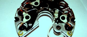
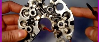
Bridges can be made of individual diodes or made as a monolithic structure (diode assembly)
Checking with a multimeter
The multimeter switches to resistance measurement mode (range 1 - 2 kOhm) or continuity with a sound signal. Before starting work, touching the contacts of the probes to each other controls the choice of the desired mode (reading 0 kOhm or sound signal, respectively).
Bridge diodes are divided into two types, conventionally called positive and negative. Positive diodes have a red body, and negative diodes have a black body. All diodes must be checked individually.
During the test, the multimeter probes are touched to the diode outputs and the result is recorded, then the probes are swapped. For a working diode, the resistance should be in the range of 400 - 800 Ohms in one position of the probes and become equal to infinity for a given range in another (the presence of a buzzer in the first case and its absence in the second).
If there is a different combination of test results (small + small or large + large resistance according to the indicator, or sound + sound, no sound + no sound), the diode is considered to be faulty.
How to repair a diode bridge?
Before repairing the generator rectifier, preparation and a general check of the performance of the diodes should be carried out. The mechanism is checked in several stages:
- Disconnecting the voltage regulators and protective casing from the bridge.
- Check for short circuit using the battery and an incandescent lamp (in case of damage to the diodes, a short circuit occurs when an incandescent lamp is connected to the terminal of the battery and the generator housing).
- Checking the condition of positive and negative elements (by connecting the plus and minus terminals of the battery and generator).
- Checking the diode bridge circuit.
- Repair or replacement of non-working elements.
Since the generator diode bridge has a low cost, every car enthusiast can repair the equipment. However, manual repairs will take a lot of time, and in order not to waste extra hours searching for information on the Internet, we suggest drivers adhere to the following recommendations:
- During the repair process, you will still have to remove the diode bridge assembly.
- The constant ingress of water into the unit causes its increased wear resistance, so it is advisable to move the rectifier to another place - less susceptible to moisture ingress. Experienced experts advise protecting the on-board network with a reliable housing under the hood.
- Pressing and unpressing the rectifier yourself will be more expensive than at a service station, but the car owner will be confident in its reliability.
- Buying diodes on the spontaneous market will be cheaper, but there is a risk of parts malfunctioning.
- Before replacing the rectifier, it is necessary to remove the insulator and the old fastener element, and be sure to transfer them to the new diode bridge.
If you want to upgrade the rectifier and install three levels of a generator relay, buy three more pairs of diode bridges that will create an independent “plus”.
Important! Checking the serviceability of parts purchased on the market is quite simple: if the “ringing” of the diode in a cold state shows from 500 to 800 Ohms, and when the engine starts, a thermal “breakdown” occurs, the design is faulty.
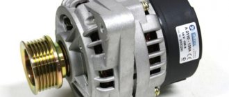
Alternating current generator device
The operation of any generator can be compared to an electric motor that operates in reverse mode, that is, it does not consume, but produces current. Based on the type of design, modern generators are divided into two types: compact and traditional. They have a common device, but differ in the layout of the housing, fan, rectifier assembly and drive pulley. Also, modern devices have three phases.
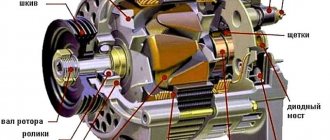
The generator consists of the following main elements:
- drive with pulley, bearings and shaft;
- rotor with field winding and slip rings;
- stator with core and winding;
- a housing consisting of two covers;
- voltage regulator;
- rectifier block or diode bridge;
- brush assembly.
Let's analyze each element of the device separately and in detail.
Frame
The housing contains all the main elements of the generator. It consists of two covers (front and back). The covers are connected to each other with bolts. For the manufacture of covers, light aluminum alloys are used, which are not magnetized and dissipate heat well. The covers have ventilation holes and mounting flanges.
The back cover contains a diode bridge and a brush holder with brushes. Also in the back cover there is an output contact through which current flows from the generator.
Drive unit
Rotation from the crankshaft is transmitted to the generator pulley and rotates the rotor. The pulley rotation speed is 2-3 times higher than the crankshaft speed. Torque from the engine is transmitted through a belt drive. Poly V-belts and V-belts can be used depending on the design. The poly V-belt is considered more versatile and modern.
Rotor
On the rotor shaft there is an excitation winding, which creates a magnetic field and, in fact, is an ordinary electromagnet. The winding is located between two pole halves (cores) necessary to regulate and direct the magnetic field. Each half has six triangular projections called beaks. There are also two copper slip rings located on the rotor shaft. Sometimes they are made of steel or brass. The excitation winding receives power from the battery through slip rings. The winding contacts are soldered to the rings.
At the front end of the rotor shaft there is a drive pulley, and at the other end the fan impeller is mounted. There may be two of them. They are needed to cool the internal parts of the generator. There are also maintenance-free ball bearings at both ends of the rotor.
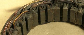
Stator
Structurally, the stator has the shape of a ring. This is the main part used to create alternating current from the magnetic field of the rotor. Consists of a winding and a core. In turn, the core consists of connected steel plates, in which 36 grooves are formed. Three windings are wound into the slots, which form a three-phase connection. There can be two winding connection schemes: “star” and “delta”. In a star circuit, the ends of each of the three windings are connected at one point. According to the “triangle” scheme, the ends of the windings are brought out separately.
Rectifier block or diode bridge
The rectifier unit performs the task of converting the generator's alternating current into direct current, which is necessary to power the vehicle's on-board network. In other words, it produces a voltage that is stable and uniform.
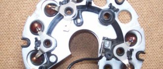
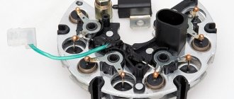
The block is also called a diode bridge, which consists of two radiator plates (positive and negative) and diodes. There are two diodes per phase. The diodes themselves are hermetically mounted into the plates. The diode bridge is shaped like a horseshoe.
From the stator winding, current flows to the diode bridge, then it is “rectified” and supplied to the output contact on the back cover.
Current passes through diodes only in one direction, and currents of reverse polarity are cut off. The diode bridge can be located in the generator housing, or it can be placed outside the housing. But most often it is attached to the inside of the back cover.
Voltage regulator
The regulator maintains the generator voltage within certain limits. Modern models use semiconductor electronic voltage regulators. They are installed on top of the brush holder block.
Voltage regulator and brush assembly
When the engine operates at high speeds, the voltage on the stator winding can reach up to 16V. Such voltage should not be supplied to the on-board network. To eliminate this, the voltage regulator, receiving current from the battery, will reduce its value. A small current on the rotor winding will create an equally small magnetic field. This means that the voltage on the stator winding will decrease.
How is the replacement performed?
Let's say checking the diode bridge shows that there is a problem. It is necessary to disconnect all wires from the generator, remove and disassemble the device. In some models, the part is attached directly to the unit with bolts, but there are devices in which the housing must be removed to access the rectifier.
Next, as part of the repair, faulty diodes are replaced - if this is economically feasible and it is difficult to find the required generator model on sale. Or they change the component entirely. Upon completion of work on the stand, the serviceability of the component and the electrical system as a whole is checked using a multimeter, and the part is assembled and installed on the car.
You can check the diode bridge yourself if you have the time and skills to disassemble the generator. But even after checking and detecting faulty diodes, you will need to select and correctly install a new element instead of the faulty one. Remember that a faulty generator can cause failure of expensive electrical equipment, short circuits and spontaneous combustion of the car. Therefore, it is better to trust repairs and diagnostics to car service technicians, who will definitely be able to call you correctly!
The simplest and roughest check
We will need an indicator screwdriver. It costs pennies and should be in every home's toolbox. You just need to first touch the 220V input of the rectifier, if the indicator on the phase wire lights up, then voltage is present, if not, the problem is clearly not in the diode bridge and you need to check the cable. If there is voltage at the input, check the voltage at the positive output of the rectifier; at this point it can reach up to 310 V, the indicator will show it to you. If the indicator does not light, the diode bridge is broken.
Unfortunately, we won’t be able to find out anything else using an indicator screwdriver. You can learn how to use an indicator screwdriver from our article.