There are many radio elements in household appliances and various devices, thanks to which everything works as it should. The malfunction of even one part has a bad effect on the operation of the entire mechanism, which may even stop functioning. One of the representatives of such important elements of electrical engineering is the diode bridge. Its breakdown does not lead to anything good, but a multimeter helps to notice the malfunction in time. We will tell you how to check a diode bridge with a multimeter, but first let’s remember what kind of part it is and how it works.
How to ring a diode bridge made of discretely arranged diodes
All parts of the bridge circuit can be ringed without desoldering. To do this, you need a multimeter that has a diode testing mode, usually combined with an audio test. The essence of the test is to measure the voltage difference between the probes.
How to properly check the serviceability of a diode bridge with a tester:
- First, make a direct connection to the device. To do this, a red probe is connected to the anode, and a black probe is connected to the cathode. With this connection, current flows freely. For a silicon diode, the voltage drop across the pn junction is approximately 500-700 mV. For Schottky diodes, the voltage drop at the transition between zones is lower and equal to approximately 300 mV.
- Next, the reverse connection is made. The red probe is connected to the cathode, and the black one to the anode. For a healthy semiconductor, the voltage drop value will be 1 or more than 1000 (usually 1500).
Direct connection of the diode bridge
Reverse connection of the diode bridge
If, as a result of the test, high values are observed in both directions or an audible signal is triggered, then the diode bridge is broken.
Principle of operation
The operation of a diode semiconductor bridge that conducts current is simple. The principle of operation is based on the property that a semiconductor diode passes electric current in one direction and does not pass in the other. So, if the charges are connected correctly, current will flow through the device.
The difference between alternating current and direct current is that it can only move in one direction. Moreover, do this in one half-cycle. During the other half of the period, it can make the opposite movement. When several diodes are connected in a circuit, they will begin to move, creating a direct current.
It is easy to assemble a diode bridge circuit. Anyone can do this. It includes four diodes, which are connected to each other by a square. Current is supplied to several opposite corners from the generator apparatus. From several other opposite angles the constant is removed. During the first period, several electrodiodes are opened and the alternating voltage wave is rectified. In the second period, several more diodes are opened. Thus, the second wave is transformed. The result is a constant voltage with a pulse frequency several times higher than that with alternating voltage.
Interesting! The presented scheme has its pros and cons. To use rectified current, the pulse component must be smoothed with a filter. Thanks to rectification, it is possible to power the transformer and reduce its volume. Among the disadvantages, note the fact that power is lost due to thermal dissipation, the voltage drops twice and the device breaks down if one diode fails.
How the device works
How to check the diode bridge in a transformer power supply using a light bulb
For this method you will need an incandescent lamp with a power of up to 100 W, screwed into the socket. The lamp is connected to the break in the power phase wire. If a short circuit occurs on the board, then when the device is connected to the network, the fuse will blow, the wire itself will blow, or the circuit breakers will be knocked out. If you check using an incandescent light bulb, then such troubles can be avoided. If there is a short circuit, the light bulb connected to the network will light up brightly. It won't burn out because the resistance of the coil will limit the current. If the electronic components of the board are working properly, the light will not light up at all or a faint glow will be observed.
Diode bridge breakdown
Safety regulations
Depending on where and which diode bridge you are testing, consider the following:
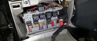
- Many modern units operate with high-voltage power supplies, that is, the bridges in them are under high voltage! Therefore, before testing, disconnect the device from the network and discharge the smoothing capacitors, which are in the photo under the scarlet arrows. This is easy to do: you can short-circuit the capacitor terminals for a second with a screwdriver, while holding it by the insulating area. If you do not take this point into account, you can lose your life!
- When the repair is completed, you should not directly connect the device to the network. First, turn it on through a lamp (150-200 W). If everything is ok, it will burn a little. But a bright light indicates a short circuit.
- Take care of your eyes and more. Parts of impulse units can explode if repaired incorrectly, and this is very dangerous!
Now you know how to test a diode bridge with a multimeter. Take on the job if you have thoroughly studied safety precautions and are confident in your abilities.
Share your experience in the comments.
We wish you safe and accurate measurements!
A simple check of the integrity of the diode bridge of the transformer power supply
If we found out using a light bulb that there are problems on the board, using an indicator screwdriver we can find out whether there is a break on the diode bridge. If the indicator lights up on the phase wire at the input to the rectifier, we carry out further checking. If the indicator does not light up, then the problem is not in the diode circuit, but in the power cable. The indicator checks the presence of voltage at the positive output of the rectifier. If it is present, then the diode bridge is not broken. We will not receive more information during such a check.
There is no breakdown of the diode bridge
Symptoms of a problem
If even one diode breaks or breaks, a voltage with dips is formed at the generator output. The battery compensates for some of the failures, however, the voltage in the on-board network drops, which affects the performance of electrical appliances and lighting equipment. Electromagnetic interference is generated, reducing the quality of the speaker system and radio receiver.
Malfunctions of the diode bridge are determined by the following factors:
- the battery runs out quickly without being recharged from the generator (the warning lamp continues to light after starting the engine);
- the battery is recharged, the electrolyte boils;
- headlights dim when driving;
- The starter is difficult to start the engine;
- The power of the air conditioner and heater decreases;
- sounds in the audio system are distorted.
The main causes of damage to semiconductors are moisture entering the bridge through the ventilation holes of the generator during vehicle operation or mixing up the “+” and “-” wires when starting the engine from the cigarette lighter.
A malfunction of the diode bridge is not visible to the naked eye, so it is necessary to use special devices
How to Accurately Test a Diode Assembly: Detailed Analysis
To check, you will need a multimeter that has a diode test mode.
Verification steps:
- Testing begins with diodes 1 and 2. To do this, the red probe of the tester is connected to the terminal with the “-” sign. Above the two center terminals there is an AC or ̴ marking. The black probe is connected in turn, first to one such terminal, and then to the second. This is a direct connection in which current flows freely. The display of the digital multimeter will show the voltage drop across the pn junction when connected directly. In foreign datasheets this value is designated as Vf. For silicon diodes it is in the range of 0.4-0.7 V. For Schottky semiconductors it is lower and equal to approximately 0.3 V. If these values are displayed on the measuring device, then the diode assembly is working.
- To clarify the results of checking diodes 1 and 2, a reverse connection is made. To do this, connect a black probe (negative) to the “-” terminal. The red probe is alternately connected to the terminals marked AC or ̴. The display should show a unit, indicating high resistance and no reverse current. If this is so, then the serviceability of diodes 1 and 2 is confirmed.
- Next, check the verification of diodes 3 and 4 under the condition of direct connection. To do this, connect the black probe to the positive, and the red one in turn is connected to the AC terminals. The display should display the voltage drop across the pn junction, which was described in detail in the first paragraph.
- To confirm the result, connect the red probe to the plus, and the black probe to the AC terminals. The display should show one.
If the diode assembly successfully passes this test, we can say with confidence that all elements are in good working order.
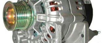
How to check a generator diode bridge
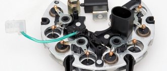
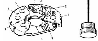
Generator diode bridge
The diode bridge of a car or motorcycle generator is designed to rectify the alternating current generated by the generator and produce direct current for charging the battery and other power consumers. A malfunction of the diode bridge leads to a complete disappearance or a significant decrease in the amount of current produced by the generator. The most accurate results can be obtained at a service station - on a bench using an oscilloscope.
One of the options for simple testing of semiconductors is a continuity test using a multimeter. However, this is an unreliable method, since the load on the device is very small, so the malfunction may not be detected.
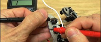
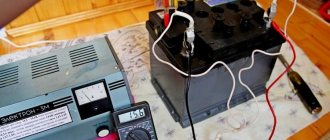
To check the diode bridge of the generator under load, use a test light, this can be a regular 12 V car lamp.
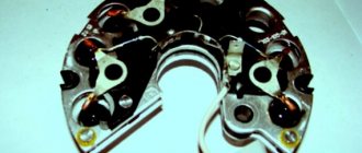
The rectifier unit consists of two aluminum plates combined into a single structure. 3 diodes are soldered into each of them. Positive and negative diodes are soldered in pairs. Checking the bridge circuit for a short circuit (short circuit) between the plates is carried out in the following way:
- The positive wire from the lamp is connected to the top plate, and the negative wire to the bottom. If the light does not light up, then there is no short circuit.
- The polarity is changed. If there is no short circuit, the light comes on.
- Positive semiconductors are checked for breakdown and breakage by pressing the positive wire from the light bulb to the top plate. The negative is alternately connected to the connection points of the semiconductors. If the circuit is working properly, the light does not light up. When changing polarity, the light should light.
- Negative diodes are tested by pressing the negative wire to the bottom plate and the positive wire to the semiconductor connection points. If the circuit is working properly, the light bulb does not light up; when the polarity is changed, it should light up.
Diagnostic methods
As practice shows, diode bridges periodically fail on any vehicle, regardless of make and model
It is also not fundamentally important whether you use diode bridges from Valeo, Bosch or any other manufacturer
Read also: End beam crane beam
Most often, one or several diodes burn out in a DM. As for the reasons, here we can highlight:
- dust ingress;
- negative impact of dirt;
- contact of diodes with oil;
- accumulation of moisture in the generator;
- polarity error when lighting;
- incorrect battery connection;
- overload in the electrical network;
- errors in the installation of electrical equipment;
- factory defects, etc.
If you set a goal, the bridge can be checked in normal garage conditions. For such tasks, use a light bulb or a multimeter.
Before starting work, remove the protective casing from the DM, and also do not forget to disconnect the terminals on the regulator. Remember that all bridges are positive, that is, positive diodes are equipped with red wires, and negative ones are black. Don't get confused.
Now in more detail about each of the methods.
Multimeter
If you decide to use a multimeter to check the bridge, you will need to perform several sequential procedures.
The whole process looks like this:
- the bridge is dismantled from the generator (no other way);
- each diode will need to be checked separately;
- the beeper mode is selected on the measuring device;
- This setting will allow you to hear a signal when the probe is shorted;
- if this mode is not available, select the 1kOhm position;
- the probes are brought to the edges of the diode;
- a measurement is made;
- the probes are swapped.
Now regarding the measurement results. Everything is fine with the diode, if in one position you see an infinity sign on the screen, in the second it gives a value in the range from 500 to 700 Ohms.
If the device shows a lower resistance value, or there is an infinity sign in two positions, you have found a faulty diode.
Bulb
Now let's see how the procedure is carried out using a regular light bulb. This is a good alternative for those cases when you don’t have a multimeter.
The most ordinary 12 V lamp will do the job.
- The DM housing is connected to the negative of your battery;
- the plate must fit tightly to the car generator;
- one end of the lamp is connected to the minus of the generator;
- the second to the positive terminal 30 through the battery;
- if the lamp is on, then one or several diodes have failed;
- check negative diodes;
- the minus of the lamp goes to the body of the autogenerator;
- plus to the axle mounting bolt;
- if the lamp lights up or starts blinking, the problem is with the negative diodes;
- Next, the positive diodes are checked;
- the plus goes to terminal 30, and the minus also goes to the mounting bolt;
- when the lamp is on, we conclude that the problem is with this group of diodes;
- additional bridge diodes also need to be tested;
- the minus remains in its place, and the plus goes to terminal 61;
- if the lamp is on, the problem is diagnosed again.
To solve the identified problem, you will need to remove the problematic diode. A new one is installed in its place.
Nobody forbids you to simply buy a completely new DM and install it in place of the old one, then the question is a more substantial amount of money.
In total, checking and repairing the bridge will take no more than 2-3 hours for a technician without much experience. If you are an experienced auto mechanic, then you definitely won’t spend more than an hour of your time on such events.
Have you had any experience in repairing or simply checking diode bridges on your car? If yes, write about it, tell us what difficulties you encountered or what tricks you know.
That's all
Thank you for attention! Subscribe, leave comments, ask questions and expect a lot of new, useful and interesting materials! (1 ratings, average: 5.00 out of 5)
(1 ratings, average: 5.00 out of 5)
Subscribe to updates and receive articles by email!
We guarantee: no spam, only new articles once a week!
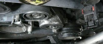
The generator is a miniature electrical station that supplies power to many components of the car: ignition, cooling, electrical wiring. Therefore, its failure will certainly entail other malfunctions. To prevent problems, you need to have this part diagnosed and repaired from time to time.
It will be useful for any motorist to know how to check the operation of a generator in a car, but first you need to understand the possible signs of a breakdown.