How to independently replace the diode bridge on a VAZ 2107
A diode bridge or rectifier is one of the parts of the VAZ 2107, the replacement of which requires almost complete disassembly of the generator.
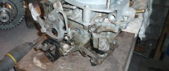
As a rule, the failure of a generator, or more precisely one of its elements, is primarily determined by a loss of battery charging. Before you begin the repair, you need to remove the generator from the VAZ 2107 engine. To do this, you will need two keys - 17 and 19. Use the 17 key to unscrew the fastening nut on the adjusting plate. This will relieve the tension on the drive belt, which can be freely removed. After this, using a 19mm wrench, you need to unscrew the nut securing the generator to the VAZ 2107 engine housing. Having removed the bolt from the holes, remove the generator from the engine and begin repairing it.
Here you will additionally need:
- Hammer;
- Heads for 8 and 10;
- Head extension
First, let's disassemble the body. To do this, unscrew the nuts located on its back cover.
To separate both halves, you need to lightly tap one of the halves with a hammer in a vertical position at the point of their connection.
Assembling a VAZ 2107 generator
Before assembling the generator, it is necessary to clean the parts from contamination. It is better to wash metal parts with gasoline, and wash windings and other complex parts with air from a compressor.
The new bearing is pressed onto the rotor using a mandrel. You can use a head or tube with a diameter that matches the size of the inner ring of the bearing.
Before installing the rear and front covers, it is necessary to check the condition of the bearing seats. They must not be damaged or scratched.
If there are cracks in the cover, they must be replaced with new ones. Bolts and nuts of poor quality must also be replaced.
The sequence of assembling the generator corresponds to the procedure for disassembling it.
After installing and connecting the generator, it is necessary to tighten the belt with the necessary force. If it is overtightened, the bearings will fail; if it is loose, the generator will slip under load and will not produce the required charging current.
Signs of generator malfunction and ways to eliminate them
The operation of the generator is controlled by a signaling device on the instrument panel. When the ignition is turned on, the window should light up and go out after the engine starts. If this happens, then everything is fine, the generator is working.
Too bright or too weak illumination of the indicator already indicates certain malfunctions of the generator system parts. In any case, insufficient battery charge always indirectly indicates problems with the generator.
The generator does not supply charging current at all
A very common occurrence is low drive belt tension. When it slips, the generator cannot operate at full capacity, and this leads to a gradual discharge of the battery. Belt slipping can also be caused by worn alternator bearings. It must be remembered that the service life of this unit is less than that of the engine, and is about 130-160 thousand km.
If the drive belt tension is weak, the generator cannot operate at full power, which leads to a gradual discharge of the battery
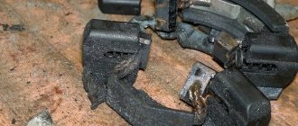
Brush sticking, the second most common problem, is caused by dirt buildup on the brush holder and brushes themselves, as well as weakened brush springs. To solve the problem, it is necessary to clean the above elements and, accordingly, replace the springs with new ones. However, serious wear of the brushes may occur, which will require their replacement.
During intensive use, sometimes the so-called burning of slip rings occurs, as a result of which contact with the generator significantly deteriorates or disappears. This problem can be solved by thoroughly cleaning and grinding the rings or turning them. Additionally, it is worth inspecting the wiring connecting the generator and the battery for breaks.
Also, the reason for the lack of charging current may be a faulty voltage regulator, which must be replaced with a new one. There are frequent cases of breakage of the excitation winding; with some experience in repair work, this can be eliminated. It is also important to pay attention to the fact that there are cases of the rotor touching the surfaces surrounding it. This may lead to partial damage. The cause is usually worn out bearings or seating areas.
Checking the voltage regulator of the VAZ 2107 generator with a multimeter
Diagnostic methods
The malfunction of the car generator is classified as critical, in which further operation of the vehicle is not allowed. You can use a multimeter to check the functionality of the generator.
Signs of abnormal operation of a car generator may include:
- no “battery” indication on the dashboard when the ignition is turned on;
- the “battery” light glows after starting the engine;
- periodic blinking of the “battery” signal indicator while driving;
- the smell of burnt electrical wiring in the generator area;
- failure to start the engine after parking.
Lack of battery charge with a faulty generator leads to problems with starting the engine. More dangerous is a malfunction associated with exceeding the current and voltage of the car battery charge.
Many car enthusiasts use a donor battery to start the engine, after which they disconnect the battery terminals to switch to charging their own battery.
If the generator is faulty, the voltage in the on-board network may be more than 17 volts, which leads to breakdown of the protective zener diodes in the engine control unit. In this case, expensive repairs to the engine control unit are required.
The generator may not work for the following reasons:
- malfunction of the voltage regulator (“pills”, “chocolates” in the slang of car enthusiasts);
- wear (destruction) of brushes;
- short circuit of the exciting winding (rotor);
- breakdown of diodes (located in the horseshoe);
- wear of bearings and bushings.
A faulty voltage regulator usually results in a lack of battery charge. In this case, the “battery” indicator light appears on the dashboard. The engine continues to run until the battery is discharged to approximately 8 - 9 volts.
During daylight hours, the battery charge may be enough for 30-50 kilometers, provided that the battery was well charged at the time the malfunction occurred.
If the output stages of the voltage regulator breakdown, a malfunction may occur due to an increase in the generator output voltage to 17 - 20 Volts. This recharges the battery. The consequence of overcharging is the process of boiling of the electrolyte. If signs of corrosion appear under the hood in the battery area, it is necessary to check the generator.
A breakdown of the diode bridge can occur when the battery is accidentally reversed (installing the terminals in the wrong polarity). Typically, diodes are punched in pairs in one arm. A faulty diode has a resistance close to zero. In this case, the stator winding of the generator operates in short circuit mode and becomes very hot.
After a few minutes of engine operation, the windings overheat, and a smell of burnt electrical wiring appears under the hood of the car. To avoid fire, the engine must be turned off and the generator checked.
Wear of the brushes leads to gradual failure of the generator. First, while driving, the charge indicator light on the dashboard begins to blink, then it begins to glow constantly. In many generator models, the brushes are changed together with the voltage regulator.
A short circuit in the generator windings can lead to a significant change in output parameters and overheating of the device.
An initial performance check can be performed without dismantling the generator. To do this, set the multimeter switch to the “constant voltage 20V” mode.
Next, connect the black probe to the negative terminal of the battery, the red one to the positive terminal. After this, you need to start the engine and let it reach a stable idle speed.
Multimeter readings ranging from 13.5 to 14.5 Volts are considered normal.
If the multimeter shows a value less than 12.8 Volts, the charging process either does not occur at all, or the charging current is extremely small. The generator is operating in abnormal mode. When the voltage is more than 14.8 Volts, the battery is overcharged. This can lead to boiling of the electrolyte, an increase in acid concentration, and destruction of the battery plates.
To check the voltage at the generator output, you need to turn on the car lamp in the open circuit from terminal 30 on the generator (the point of contact with the thick wire leading to the positive terminal of the battery or starter).
When checking, you should evaluate the degree of tension of the generator belt. Using a simplified method, this can be done by pressing on the belt with your finger.
The amount of deflection should be within 0.5 - 1 centimeter. At the same time, you should check the degree of belt wear. To determine the reasons for abnormal operation of the generator and perform repair work, dismantling the generator is required.
The test begins with monitoring the functionality of the voltage regulator. To do this, the regulator is removed from the generator and a simple electrical circuit is created.
Any car interior light bulb can be used as an incandescent lamp. If voltage regulator 3 is working properly, lamp 6 should not glow at full power.
When connected in parallel with the lamp (brushes) of a multimeter, its readings should be from 5.0 to 10.0 Volts. If the multimeter readings fall outside these limits, the regulator must be changed.
The design of some generator models allows for the possibility of replacing the regulator without dismantling the device.
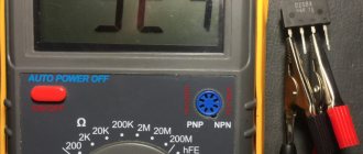
Next, check the exciting winding of the generator for breakdown. To do this, set the multimeter to resistance measurement mode at a limit of 200 kiloOhms. The probes are connected: black - to the commutator lamella, red - to the metal part of the armature. The resistance should be more than 100 kiloohms or higher than the upper limit of measurement, as shown in the photo.
The resistance between the lamellas (rotor windings) is usually 0.5 - 2 Ohms.
Checking the stator begins with checking the windings for breakdown. To do this, the red probe of the multimeter is connected to the metal part of the stator, the black probe is connected in series to the windings.
The resistance must be above the upper measurement limit. Then the resistance between the winding contacts is measured. They should differ by no more than 5%. The measurement limit of the multimeter is set to 200 ohms.
If the winding has an electrical breakdown, a short circuit of the turns or a break, it must be replaced. There are workshops that rewind stators and rotors.
To check the health of the diode bridge, the multimeter measurement mode is switched to the “diode” test. Then the diodes (their number on a horseshoe is usually 9) are sequentially “ringed” in forward and reverse connection. In the forward direction (black probe to the cathode) the resistance is 550 - 700 Ohms, when switched in reverse it is greater than the maximum measurement limit.
When the diodes breakdown, the resistance in all directions will be practically zero. This diode should be changed. The difficulty of replacing a diode lies in the fact that the diodes in generators are not soldered, but spot welded to ensure reliable contact at different temperature conditions.
A car generator is an important part of a car's electrical equipment. At the first sign of inoperability, it is necessary to check it using a multimeter.
Not every driver knows what a VAZ 2107 charging relay is; in addition, this device is extremely rarely remembered. The charging relay is a voltage regulator or “chocolate bar” that is located in the generator.
Owners of the Seven only pay attention to this detail after problems with the battery not charging begin.
To prevent it from happening at one point, which negatively affects the engine, it is necessary to periodically monitor the operation of the charging relay.
The main purpose of the voltage regulator relay on the VAZ 2107, and any other car, is to maintain a stable and sufficient charging current for the on-board network and the car battery, as well as to level out voltage surges in the generator.
Variations in the generated voltage would occur as the generator rotates at different frequencies. When the power drops below 12V, the battery stops charging, and the entire bot network no longer functions at 100%.
If the voltage exceeds 16 Volts, this can lead to boiling of the battery, as well as failure of on-board devices.
Most VAZ 2107 cars of the carburetor and injection type are equipped with generators with built-in charging relays. The charging relay on such VAZ 2107 vehicles is located directly on the side of the generator opposite the pulley.
To maintain an acceptable battery charge, the alternator requires 13.6 to 14.6 volts of power. The voltage regulation circuit is carried out using an electrical circuit, which is located on a printed circuit board (chocolate board) or in the form of a single semiconductor module (tablet) with brushes.
The switch located inside the generator is usually not able to adequately respond to the ambient temperature due to its location close to the running engine.
The built-in relay is sometimes replaced with a three-level voltage regulator, which is due to the greater efficiency of the product due to manual adjustment of the output voltage.
If you suspect a faulty operation of the voltage regulator relay, then you must first check the voltage at the battery terminals with the car running. The power supply must be no lower than 13 and no higher than 14.6 Volts. The reasons for such increased or decreased voltage can be caused by the following factors:
- charging regulator malfunction;
- failure of the generator itself;
- lack of contact in the electrical connections of the battery or generator.
To check the serviceability of the chocolate bar, it is necessary to remove it from the generator. This must be done by unscrewing two bolts.
We independently change the diode bridge on a VAZ 2107
A modern car is literally crammed with complex electronics, which are not so easy to repair. It is for this reason that car owners, at the slightest problem with on-board electrical devices, do not fool themselves, but immediately contact the nearest car service center. However, there are exceptions to this rule. For example, if the diode bridge on a VAZ 2107 is burnt out, then you can completely refrain from visiting a car service center and replace the burnt-out device yourself. Let's figure out how this is done.
The main function of the diode bridge on the VAZ 2107
The diode bridge is an integral part of the VAZ 2107 generator. The car's generator produces alternating current. And the main task of the diode bridge is to convert the alternating current of the generator into direct current of the on-board network with subsequent charging of the battery. That is why car enthusiasts usually call a diode bridge a rectifier block. The peculiarity of this unit is that it allows direct current to pass only towards the battery. The current passed through the diode bridge is subsequently used to ensure the operation of the heater, low and high beam headlights, side lights, audio system, etc.
The charging voltage in a VAZ 2107 car ranges from 13.5 to 14.5 volts. To provide the required voltage, 2D219B diodes are most often used in the diode bridges of this car.
And there is a diode bridge inside the VAZ 2107 generator. And in order to get to the bridge, the car owner will first have to remove and disassemble the generator. There are no other options.
How to ring a diode bridge on a VAZ 2107
To find out whether the diode bridge is working, the car owner does not need to have any special skills. All he needs is basic knowledge of electrical engineering and a couple of instruments:
- household multimeter;
- 12 volt incandescent light bulb.
Before starting the test, make sure that the battery is charged. It is desirable that the battery charge level is maximum.
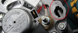
- The base of the diode bridge (i.e., the thin plate into which the diodes are screwed) is connected to the negative terminal of the battery. The plate itself must be firmly secured to the generator housing.
- Two wires are connected to the light bulb. Then one of them should be connected to the positive terminal of the battery, and the second wire should first be connected to the output provided for the additional diode, and then with the same wire you should touch the positive output bolt of the diode and the connection point of the stator winding.
This verification method is similar to the one described above, with the exception of two nuances.
- The negative terminal of the light bulb is connected to the positive terminal of the battery.
- The second wire of the light bulb is connected to the negative terminal of the battery. Then the same points are checked as indicated above, but here the control light should be on. If the light does not light (or it lights up, but very dimly), then there is a broken bridge.
Before checking the diode bridge using this method, it will need to be completely removed from the generator. There are no other options. With this testing method, each diode will have to be ringed individually.
- The multimeter switches to ringing. In this mode, when the electrodes touch, the multimeter begins to beep (and if the multimeter’s design does not provide sound signals, then in the ringing mode, a resistance of 1 kOhm should be displayed on its display).
It should be noted here that when burnt diodes are discovered, today no one fools themselves by replacing them. A bridge with a burnt-out diode is simply thrown away. Why? It's simple: firstly, the burnt-out diode will have to be desoldered very carefully. And for this you need to have the skill of working with a soldering iron, which not everyone has.
And secondly, diodes of the 2D219B brand must be installed in the bridge, and only them. Yes, there are many other diodes on the market with similar electrical characteristics. There is only one problem with them: they burn, and very quickly. And finding the above-mentioned 2D219B on sale is becoming more and more difficult every year. I don’t know why this happens, but this is a fact that I personally encountered.
Signs and causes of diode bridge failure
As mentioned above, a generator equipped with a diode bridge is the most important component of a car. If the alternator fails for some reason, the battery will stop charging. And this is the only sign of a faulty diode bridge. Without additional recharge, the battery will work for a few hours at most, after which the car will be completely immobilized. A diode bridge fails when one or more diodes burn out in it. Here are the reasons why this happens:
How to check a diode bridge with a multimeter?
Proceed in the following sequence:
Remove the diode bridge from the generator (otherwise the test will not work). Each diode must be tested separately.
Set the multimeter to “beeper” mode. In this case, when the probes are closed, a characteristic squeak will be emitted. If there is no such function, you can set the tester switch to the “1 kOhm” position.
Touch the probes to the edges of one diode and take measurements by swapping the probes. The diode can be considered serviceable if it shows infinity in one direction and about 500-700 Ohms in the other.
If in both measurements the resistance is too low or, conversely, infinite, then the diode (group of diodes) is faulty.
How to find a generator malfunction without removing it from the car
Diagnostic methods
In connection with the successful elimination of the problem in the generator, I decided to summarize the experience and write separate articles on diagnostics and troubleshooting using the example of generator 9412.3701 from the VAZ-2107. If you have established for sure that it is the generator that is faulty, then we arm ourselves with a multimeter or a test light (screwdriver), connected to the battery.
First, remove the positive “ ” terminal from the battery to avoid accidental short circuit, then disconnect all contacts from the generator and, bending the latches, remove its back cover (the design of which provides for this). In this way we can carry out a general check of the diode bridge and stator winding, as well as the rotor. To check the voltage regulator, you need to remove it from the car's generator.
So, let's get started: switch the multimeter to the “diode continuity/circuit integrity check” mode.
Fig.3
1. First, check the generator for a short circuit to ground.
We press the positive “ ” probe of the multimeter to terminal “30” of the generator, and the negative “-” probe to its body. In good condition, the diode bridge does not pass current in this direction, there is no sound signal, and the light bulb does not light up.
| Fig. 4 “1” - Resistance tends to infinity - no current passes |
When an alarm occurs or the control lamp lights up, we have a short circuit of the diode bridge or stator winding to ground.) To exclude the stator in this case, it is necessary to remove the diode bridge from the generator.
2. Check the positive diodes for breakdown.
We press the positive “ ” probe of the multimeter to terminal “30” of the generator, the negative “-” to the terminals of the winding and diodes (generators type 9412.3701, where the bolts are insulated from the terminals with textolite washers and are connected to ground), or one of the bridge mounting bolts (generators type 37.3701, where the bolts are connected to the terminals, but isolated from the “ground” - Fig. 5).
If the diodes are working properly, then the resistance tends to infinity, and the light bulb does not light up. If even one of them is “broken,” the light comes on and the multimeter beeps. When changing polarity, they must pass current.
3. Check the negative diodes for breakdown.
To do this, press the positive “ ” probe of the multimeter to the terminals of the winding and diodes (generators type 9412.3701), or to the bridge mounting bolts (generators type 37.3701—Fig. 5). We press the negative “-” against the generator housing.
If the resistance tends to infinity and there is no sound signal, the lamp does not light - the negative diodes are working. When changing polarity, they must pass current.
4. We check additional diodes for breakdown.
We press the positive “ ” probe of the multimeter to the input “61” of the generator. Negative “-” probe to the terminals of the winding and diodes (generators type 9412.
3701), or to the bridge mounting bolts (generators type 37.3701—Fig. 5). If the resistance tends to infinity and there is no sound signal, the lamp does not light - the additional diodes are working.
When changing polarity, they must pass current.
To determine a break in the diode, you will also have to remove the diode bridge from the generator.
It is worth noting that testing diodes with a multimeter and, to a lesser extent, with a light bulb, in which the diodes are tested under load, are not a 100% effective method.
For this, there are more accurate instruments, such as an oscilloscope.
If the diode bridge is working properly, then we proceed to checking the stator winding.5. Check the stator winding for open circuit.
We alternately connect the multimeter probes between all three terminals of the stator winding.
| Fig. 9 “000” - current flows through the circuit |
A sound signal or a lit lamp in all three cases tells us about the integrity of the winding.
6. Check if the stator winding is shorted to ground.
We connect the probe to one of the winding terminals, and the other to the generator housing. If the resistance tends to infinity, there is no sound signal, the lamp does not light - there is no short circuit.
| Fig.10 |
7. Check the stator winding for interturn short circuit.
To do this, switch the multimeter to the “200 Ohm” resistance measurement mode and connect the probes between all three terminals of the stator winding. The resistance should be 0.2-1.2 ohms and be the same between all three terminals.
To check the rotor winding, it is necessary to remove the brush assembly with the voltage regulator.
8. Check the rotor winding for breaks.
To do this, we connect the probes to the contact rings of the rotor - the multimeter should emit a sound signal, and the indicator light should light up accordingly, which indicates the integrity of the circuit.
9. Check that the rotor is shorted to ground.
We connect one probe to the slip ring, and the second to the generator housing. If “Resistance tends to infinity”, there is no sound signal, the lamp does not light, then everything is in order.
10. Let's check the rotor winding for an interturn short circuit.
We similarly switch the device into the “200 Ohm” resistance measurement mode and connect the probes to the slip rings. The rotor winding should have a resistance of 1.5 - 5.0 Ohms, depending on the type of generator.
If one of the above problems is detected, it is necessary to remove the generator and repair it or replace the failed part. In the next article I will tell you how to correctly find a broken diode and check the relay regulator for serviceability.
The process of replacing the diode bridge on a VAZ 2107
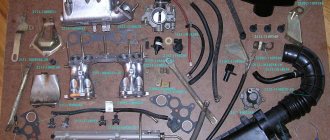
Before we get started, let's select the necessary tools. Here's what we need:
- open-end wrench 17;
- open-end wrench 19;
- socket head 8;
- 10mm socket with long wrench;
- flat screwdriver;
- a new diode bridge for the VAZ 2107 (cost about 400 rubles);
- hammer.
Sequencing
When getting started, you should understand the following: before removing the diode bridge, you will first have to remove the generator and disassemble it almost completely. Without this, it will not be possible to get to the diode bridge.
- Using a 19-mm open-end wrench, unscrew the fastening nut holding the generator bracket. The generator is removed.
Video: changing the diode bridge on a VAZ 2107
One mechanic I know, who was dismantling the diode bridge of the “seven” before my eyes, several times drew attention to the following nuance: if you have already disassembled the generator, please check not only the diode bridge, but also everything else. And special attention should be paid to generator bearings. They must be checked for lubrication and play. If even a very slight play is detected, it’s time to change the bearings. Moreover, it is “bearings”, not a bearing. This is the second important nuance: under no circumstances should you leave one old bearing and one new one in a VAZ generator, because such a design will last a very, very short time. I decided to change the generator bearings - change everything. Or don't touch them at all.
Removing the VAZ 2107 generator
First of all, you should disconnect the battery terminals. To make work easier and improve access to the generator, it is better to remove the battery from the car. The further order of work is as follows:
- disconnect the generator connector;
- remove the insulating cover from the terminal, unscrew the fastening nut using a 10mm wrench;
- disconnect the terminal;
- loosen the generator by unscrewing the nut and remove the belt;
- remove the adjusting bar by unscrewing the fastening nut;
- unscrew the lower fastening nut and remove the bushing with the bolt;
- get the generator.
About installing an additional diode
Installing an additional diode is quite rare. Why is this being done? In order to slightly increase the voltage of the on-board network. The need for this increase arose due to new laws. As you know, in 2022, changes were made to the traffic rules, forcing drivers to constantly drive with their running lights on. And owners of classic VAZ models are forced to constantly drive with their low beams on. In such a situation, both battery charging and on-board voltage drop significantly. To somehow solve this problem, craftsmen install additional diodes, which are located between the voltage regulator terminals and the common output wires for the additional diode, as shown in the figure below.
For installation, KD202D diodes are usually used, which can be found in any radio parts store.
If the above diode is not available, you can choose any other one. The main thing is that the direct forward current is at least 5 amperes, and the maximum permissible reverse voltage is not lower than 20 volts.
So, in order to change the diode bridge on a VAZ 2107, you do not need to go to the nearest service center and pay a mechanic 800 rubles. Everything can be done on your own, and in a fairly short time. To remove and disassemble the generator, 20 minutes is enough for an experienced car enthusiast. It will take a beginner more time, but in the end he will cope with the task. All you need to do is follow the recommendations given above exactly.
Checking with a control lamp
- Connect the diode bridge plate (housing) to the negative terminal of the battery, and it should be pressed tightly against the generator body.
- We take the control and connect one end to the “positive” terminal of the battery, and connect the other end to the output terminal of additional diodes. After this, to the “positive” terminal bolt and to the connection points of the stator winding, we perform the actions described in the photo.
- If the light bulb is working properly, it should not light up when touched. If it does catch fire, you can safely conclude that the diode bridge is broken.
Checking the diode bridge on the VAZ 2107 generator
In order for the car to be started, it contains a battery. In order to restore the battery capacity after starting the engine and ensure the normal operation of all electrical appliances, devices such as generators are used in the design of cars. Initially, they generate alternating current, and to convert it to direct current, a rectifier unit or diode bridge is used. We will look at how to check the diode bridge on a VAZ 2107 generator with your own hands below in the article.
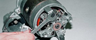
Disassembling the VAZ 2107 generator
For a comprehensive repair, you need a puller to remove the bearing from the shaft, a mandrel for pressing and knocking out the bearing in the generator cover.
- unscrew the nut securing the pulley and impeller using a socket wrench, holding the rotor with a screwdriver so that it does not turn;
- dismantle the pulley and impeller, remove the key, remove the washers from the shaft;
- unscrew the screws securing the voltage regulator relay and remove it, having first disconnected the wire block;
- remove the regulator relay along with the brush assembly;
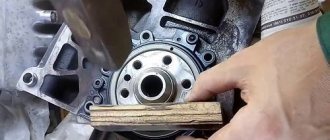
- unscrew the nuts and remove the bolts securing the generator cover;
- knock down the front cover by hitting the shaft with a rubber hammer (the cover must be rested against a wooden block);
- remove the spacer sleeve from the shaft;
- check the condition of the bearing in the front cover;
Tip: To check the bearing, you need to rock the inner race of the bearing while holding the cap. If there is play, the bearing must be replaced.
- if necessary, unscrew the bearing mounting nuts;
Attention: if the nuts do not unscrew, you should cut off the ends of the fastening bolts. During assembly, it is necessary to install new bolts and, after tightening the nuts, rivet their ends with a core.
- knock the bearing out of the cover using a drift (mandrel);
- rest the back cover against a pair of wooden blocks and knock out the rotor using a soft metal drift and a hammer;
- check the condition of the rear bearing (similar to the front);
- if necessary, replace the bearing by pulling it from the rotor with a puller;
- unscrew the nuts holding the VAZ 2107 diode bridge and the winding terminals;
- remove the bolts;
- remove the stator winding;
- visually check the condition of the winding;
- if the winding has breaks or has turned black from overheating, replace it;
- remove the generator output nut and insulating washer;
- dismantle the diode bridge;
- remove the capacitor by unscrewing the fastening screw;
- remove the bolt securing the rectifier unit;
- check the rotor and stator windings with a test lamp;
- check the diode bridge of the VAZ 2107 generator for broken diodes.
VESKO-TRANS.RU
AutoNews / Reviews / Tests
- Home
- Auto garage
- How to Check the Diode Bridge of the VAZ 2107 Generator
How to Check the Diode Bridge of the VAZ 2107 Generator
How to check the diode bridge of a VAZ generator with your own hands
Welcome friends to the DIY car repair website. The generator is, without exaggeration, the main component of the car. Its task is to power the entire electronic part of the vehicle while driving (cassette recorder, head light, navigator, etc.).
How to check generator diode bridge
When the generator fails, the entire load is transferred to the battery. As a result, after just a few hours the car is one hundred percent immobilized.
Most car owners immediately go to 100, where they spend considerable money on repairs. Don’t rush – the problem in 90% of cases lies on the surface.
If you know how to check the diode bridge of a generator, you can quickly identify the fault, correct it and save money.