Lada K alina 2 . CHECKING AND REPLACING THE VOLTAGE REGULATOR ON THE CAR
You will need: a flat-blade screwdriver, 8", 12" wrenches, 7", "8", "24" socket wrenches, a hammer, a DC voltmeter, a megger.
The operation of the voltage regulator is to continuously automatically change the generator excitation current so that the generator voltage is maintained within specified limits when the rotation speed and load current change.
If necessary, you can check and replace the voltage regulator without removing the generator from the car.
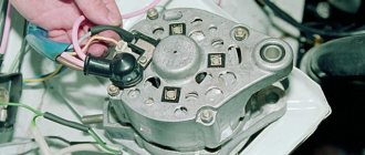
Shown is working on a car without air conditioning. On a car with air conditioning, a generator of a different model is installed, and to remove the relay-regulator, the generator must be removed from the car. 1. Move the rubber boot aside and connect the “plus” wire and the “minus” wire to the generator housing.
2. Start the engine and turn on the headlights.
3. After 15 minutes of engine operation at medium speed, measure the voltage; it should be 14.4-15.1 V. If undercharging or overcharging is observed (the voltage does not fall within the specified limits), replace the voltage regulator.
4. The serviceability of the capacitor can be checked with a megger or tester (on a scale of 1-10 MOhm). Connect the tester probes to the capacitor contacts. Before connecting, the device shows infinity. At the moment of connection, the resistance decreases, and then again tends to infinity. In this case, the capacitor is OK.
The faulty capacitor is replaced together with the rectifier unit as follows.
1. Disconnect the wire from the negative terminal of the battery. 2. Disconnect the wiring harness block from the generator terminals.
12. Check the serviceability of the voltage regulator. Connect a 12V test lamp to the brushes. Apply a voltage of 12 V “plus” to the terminal, and “minus” to the “ground” of the brush holder. In this case, the control lamp should light up.
13. Set the voltage to 15-16 V - the lamp should go out. If the lamp is on or off in both cases, then the regulator with brush holder is faulty and needs to be replaced.
14. Install the voltage regulator in the reverse order of removal.
As already mentioned in previous articles, the main malfunctions of the generator are failure of the diode bridge, brushes with a voltage regulator, or even an open circuit in the winding of the device. Below I will give some of the types of diagnostics using a multimeter that anyone can perform independently if they have this device.
Changing the generator regulator relay on Lada Kalina
A three-phase voltage regulator (charging relay) is installed on the generator. Responsible for maintaining the voltage of the on-board network within a given limit in all operating modes.
The output voltage may be affected by changes in rotor speed, electrical load, and ambient temperature.
Failure is considered one of the most common problems associated with the operation of the generator. Replacing an element does not require practical skills.
Integral charging relay Saransk KALINA (B) (gen. 9402.3701-06) (kb=21)
Multifunctional voltage regulator with brush assembly 849.3702 is designed to automatically regulate the voltage at the generator output within specified limits in all operating modes of the electrical equipment system, when changing the generator rotor speed, electrical load, and ambient temperature.
Design Features
- To smooth out transient processes and reduce mechanical loads on the generator drive belt, the voltage regulator has the functions of smooth excitation of the generator and a smooth response to a connected electrical load with a maximum duration of 2.5±0.5 seconds.
- The voltage regulator provides the ability to lightly indicate generator set faults by high and low voltage at the generator output, low voltage on the generator phase (for example, in the event of a break in the generator drive belt), as well as in the event of a short circuit in the excitation circuit.
Applicability
Cars VAZ-1117, VAZ - 1118, VAZ - 1119 Kalina, VAZ 2170, VAZ -2171, VAZ -2172, LADA GRANTA, etc. with generator 9402.3701-06.
Possibility of use
This voltage regulator is used in conjunction with rectifier limiting units without additional diodes as part of generators.
Reliability
In order to increase the reliability of the voltage regulator, it provides a number of protections against emergency modes: against short circuits in the excitation circuit, in the control lamp circuit, and overvoltage protection at the input of the voltage regulator.
Climatic performance
Voltage regulators are produced in climatic version O category 2 according to GOST 15150. The regulators meet the requirements for resistance to climatic influences according to GOST 25467. The regulators meet the requirements for electromagnetic compatibility of GOST 28751.
Technical characteristics of a multifunctional voltage regulator with a brush assembly (MFRN) 849.3702
| Technical data | 849.3702 |
| Operating temperature range, ? C | — 50 …+125 |
| Regulation voltage from the battery at t? = 25±10?C and generator load 5A, V | 14,25 … 14,75 |
| Maximum output circuit current, A | 5,0 |
| Thermal compensation coefficient Ureg, mV/?С | -7,0 ± 1,5 |
| Residual output voltage at current 5A, V | no more than 0.8 |
| Upper threshold of output indication, V | 16,1 … 17,2 |
| Lower threshold of output indication, V | 10,6 … 11,7 |
| Indication threshold for low phase voltage, V | 3,5… 8,0 |
| Duration of smooth load connection (LRC function), sec | 2,5 ± 0,5 |
| Maximum permissible long-term exposure to increased supply voltage, V | 30 |
| Maximum permissible pulse overvoltage according to GOST 28751, V | impulse type 5, severity level II, functional class B |
| Threshold current of protection along the excitation circuit, A | 7,0 … 12,0. |
| Threshold protection current along the indicator element circuit, A | 1,0 … 2,0. |
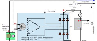
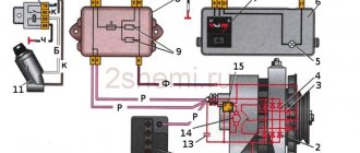
Connection diagram for multifunctional voltage regulators with a brush assembly (MFRN) 849.3702 as part of a generator set
- generator
- voltage regulator
- generator field winding
- stator winding
- indicator lamp or LED
- ignition switch contacts
- rectifier unit
- accumulator battery
Replacement process
The process of removing the generator on Kalina depends on whether it has a tensioner on it or not. A belt without a tensioner can only be removed together with the generator or simply cut (if it’s old).
Use a 13 key to loosen the tensioner and remove the belt.
By pressing the latch, we snap off the plastic block.
Lift the boot and unscrew the nut by 10.
The mounting bolts are located at the top and bottom of the generator.
The latches are located on the side surface of the cover.
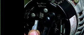
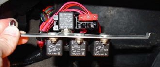
Mounting the regulator relay: 1 – contact under the bushing, 2 – bolts securing the relay body.
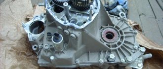
View of the generator with the relay removed.
After assembling the unit, it is necessary to check the reliability of the wire connections and tighten the generator belt.
Important! Before installing a new generator charging relay on Kalina, it is recommended to check its condition: make sure that the brushes are intact (they must protrude from the relay housing by at least 5 mm ); easy, without delay, clicking into the initial position after pressing.
Critical wear of the brushes on the old relay.
Briefly about articles and applicability
We should talk about the applicability of a particular charging relay after the model of the generator from which it was removed has been installed.
9402.3701-06 or 9402.3701-14 ( 14 V , 85 A were predominantly installed on Kalina, Granta and Priora . Part numbers of compatible voltage relays:
- KZATE "Orbita" (Saransk) 849.3702 , costing 500-750 rubles .
New voltage regulator made in Saransk.
Important ! On Priors with a generator 3701010 , which has an output current of up to 115 A, is not interchangeable with the Kalinovsky one !
Checking an Individual Regulator
Checking the voltage regulator of the G-222 generator: 1 - battery; 2 - voltage regulator; 3 - control lamp.
As a rule, separate voltage regulators were installed on old cars, including domestic VAZs. But some manufacturers continue to do this to this day. The verification process is similar. To do this, you need to have a power supply with a voltage regulator, a 12 V light bulb, a multimeter and a directly tested regulator.
To check, you need to assemble the circuit shown in the figure. The process itself is similar to the one above. In normal condition (at a voltage of 12 V), the light bulb lights up. When the voltage value increases to 14.5 V, it goes out, and when it decreases, it lights up again. If during the process the lamp lights up or goes out at other values, it means that the regulator has failed.
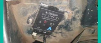
Checking relay type 591.3702-01
Relay test diagram type 591.3702-01
You can also still find a voltage regulator of type 591.3702-01, which was installed on rear-wheel drive VAZs (from VAZ 2101 to VAZ 2107), GAZ and Moskvich. The device is mounted separately and installed on the body. In general, the test is similar to that described above, but the differences are in the contacts used.
In particular, it has two main contacts - “67” and “15”. The first of them is a minus, and the second is a plus. Accordingly, to check it is necessary to assemble the circuit shown in the figure. The verification principle remains the same. In normal condition, at a voltage of 12 V, the light bulb lights up, and when the corresponding value increases to 14.5 V, it goes out. When the value returns to its original value, the light comes on again.
A classic regulator of this type is a device of the PP-380 brand, installed on VAZ 2101 and VAZ 2102 cars. We provide reference data regarding this regulator.
| Adjustable voltage at regulator and ambient temperature (50±3)° C, V: | |
| at the first stage | no more than 0.7 |
| on the second stage | 14,2 ± 0,3 |
| Resistance between plug “15” and ground, Ohm | 17,7 ± 2 |
| Resistance between plug “15” and plug “67” with open contacts, Ohm | 5,65 ± 0,3 |
| Air gap between armature and core, mm | 1,4 ± 0,07 |
| Distance between second stage contacts, mm | 0,45 ± 0,1 |
Testing a three-level relay
Regulated power supply
Some car owners install on their cars, instead of standard “chocolate bars,” three-level relays, which are technologically more advanced. Their difference is the presence of three voltage levels at which the battery power is cut off (for example, 13.7 V, 14.2 V and 14.7 V). The appropriate level can be set manually using a special regulator.
Such relays are more reliable and allow flexible adjustment of the cutoff voltage level. As for checking such a regulator, it is completely similar to the procedures described above. Just do not forget about the value that is set on the relay, and accordingly, check it with a multimeter.
Generator check
There is one method by which you can check the performance of a car generator equipped with a regulator relay 591.3702-01 with diagnostic elements. It is as follows:
- disconnect the wires that went to pins 67 and 15 of the voltage regulator;
- connect a light bulb to it (excluding the regulator from the circuit);
- Remove the wire from the positive terminal of the battery.
If, as a result of these actions, the engine does not stall, then we can say that the car’s generator is in order. Otherwise, it is faulty and needs to be checked and replaced.
Causes and symptoms of malfunction
The regulator will need to be replaced if the part fails. This can happen for several reasons:
- Short circuit in the circuit , which led to its breakdown. This happens quite often, since the “relay” is a power source, and there is no fuse between it and the rotor.
- Brushing of brushes resulting from friction against the rotor .
You can find out about problems with the operation of the generator, in particular with the charging relay, by changing the voltage of the on-board network.
In practice, during the operation of the car this is determined by the following symptoms:
- Headlight beams of different brightness . When you press the gas pedal they light up brighter, at idle they dim.
- An undercharged battery will affect the morning start-up. The starter turns much harder than usual.
Battery overcharging due to increased voltage . It can affect you in several ways:
- Electrolyte boiling in jars . It will manifest itself as a sharp, unpleasant odor emanating from the battery;
- Frequently blown fuses . If they are missing, the “weakest” part of the wiring will burn out (places with pockets of copper oxidation, poor contacts).
Traces of electrolyte are visible along the edges of the battery. This occurs due to overcharging.
Generator check
Start the engine, let it run for a few minutes, then press the gas pedal and bring the engine crankshaft speed to 3,000 min-1.
Turn on all consumers: external lighting, high beam headlights, heated rear window, heater fan, windshield wiper, hazard warning lights, etc. Using a voltmeter, measure the voltage at the battery terminals, which should be above 13 V. If this is not the case, the generator windings are faulty (open or short circuit), voltage regulator with brush assembly, or contact rings of the generator rotor are oxidized. To ensure that the voltage regulator is working properly, turn off all consumers except the high beam headlights and measure the voltage again. It should be within 14.4-15.1 V. If the voltage differs from the specified one, the regulator should be replaced. You can remove the brush holder with the voltage regulator without removing the generator from the car. The procedure for removing the regulator is shown in the “Removing and disassembling the generator” section, p. 178. To check the valves of the rectifier block of the generator, it is necessary to disconnect the wires from the battery, the generator and from the “+” terminal of the voltage regulator “Plus” of the battery through a lamp (1-5 W, 12 V), connect to the “B+” terminal of the generator, and “ minus" - to his body. If the lamp is on, then there is a short circuit in both the block of “positive” and the block of “negative” valves (for clarity, the brush holder with the voltage regulator has been removed). To check the short circuit in the “positive” valves, connect the “+” battery through a lamp to the “B+” terminal of the generator, and “-” to the terminal of one of the phase windings of the stator. If the lamp is on, one or more positive valves are broken.
To check the short circuit in the “negative” valves, connect the “+” battery through a lamp to the output of one of the phase windings of the stator, and “-” to the generator housing. If the lamp is on, one or more negative valves are broken or the stator windings are shorted to the generator housing. To prevent short-circuiting of the windings, remove the generator from the car and, having disconnected the windings from the voltage regulator and rectifier unit, check their short circuit to ground using a lamp or ohmmeter. The generator valves can also be checked with an ohmmeter without connecting the battery and test lamp. A break in the valves is determined by a sharp decrease in the output current (voltage drop under load). However, this can also be a consequence of a break or short circuit in the generator windings. The serviceability of each valve can be determined only with a removed rectifier unit using an ohmmeter or a test lamp. If the rectifier unit fails, it is recommended to replace it as an assembly. It is possible to replace individual valves, but this will require repressing them in the holder - an operation that requires care and skill. Before checking the stator windings, it is recommended to remove the generator rectifier unit.
To check for open circuit in the stator windings, connect the tester probes (in ohmmeter mode) to the terminals of the stator winding. If the ohmmeter shows infinity, then there is a break in the winding. We check the other two windings in the same way.
To check for a short circuit between the stator windings, connect the tester probes between the terminals of the two windings. The ohmmeter should show infinity, otherwise the windings are short-circuited. Check the other two windings in the same way.
To check whether the stator winding is shorted to ground, connect the tester probes to the winding terminal and the generator housing. The ohmmeter must show infinity, otherwise the winding shorts to ground. Check the other two windings in the same way. Inspect the stator windings. There should be no signs of overheating on the insulation of the windings, which is a consequence of a short circuit in the valves of the rectifier unit. If there are signs of overheating on the windings, the stator must be replaced
To check for a break in the rotor winding, connect the tester probes to the slip rings. If the ohmmeter shows infinity, then there is a break in the winding.
To check the short circuit of the rotor winding to ground, connect the tester probes to the slip ring and to the rotor shaft (or pulley). The ohmmeter should show infinity, otherwise the winding is shorted to ground.
Replacing the voltage regulator on Kalina
Today we’ll talk about removing the generator brushes on a Lada Kalina car. In order to remove the voltage regulator with brushes, you need to remove the plastic cover of the generator. After removing the cover we will need a key for 8 and 13.
Use a size 8 wrench to unscrew the 2 bolts, and use a size 13 wrench to loosen the nut.
Then we remove the regulator with brushes. If necessary, we replace the part with a new one. Install in reverse order.
The minimum permissible height of the brushes must be at least 5 millimeters. If this value is not reached during measurement, then the part must be replaced along with the voltage regulator. The price for a voltage regulator along with alternator brushes for a Lada Kalina will be about 350-400 rubles.
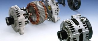
Main Generator Components
In general, a generator is a converter that creates electrical energy from mechanical energy. On all cars, the design and operating principle of these devices are similar. The design consists of the following components:
- The stator winding, a thick copper wire is used for it, since it is with its help that voltage is generated.
- The rotor winding is excitation. Without it, it is impossible for current to appear in the stator winding. In order for any potential difference to appear in the frame, the presence of two components is necessary - rotation and a magnetic field. Thanks to the generator belt on the Kalina, the rotor rotates. It is its winding that fulfills these two conditions - a magnetic field is created around it, and it rotates around its axis.
- The rotor is equipped with slip rings, to which voltage is supplied using a brush assembly.
- A pulley mounted on the rotor allows rotation to be transmitted from the crankshaft via the generator belt on the Kalina.
- A mechanical or electronic voltage regulator changes the voltage on the rotor winding. Due to this, the generator produces a stable voltage.
- The block of semiconductors (valves) mentioned earlier is necessary to convert three-phase alternating voltage into unipolar direct voltage.
- Covers with bearings are designed for rotor alignment and normal operation of the unit.
- The capacitor allows you to get rid of residual alternating current after rectification.
Video on removing the voltage regulator with brushes Lada Kalina
If the voltage regulator unit, capacitor and not a tight fit of the brushes are faulty, or if they are worn out, the vehicle's supply voltage deviates from the norm. In this case, it is necessary to check the above listed elements and, if necessary, replace them. In this article we will talk in more detail about diagnosing and replacing generator elements in a Lada Kalina car.
To remove the Lada Kalina voltage regulator you will need the following tool:
flat-blade screwdriver, 8mm and 10mm open-end wrenches and 7mm, 8mm and 24mm socket wrenches, hammer, soldering iron, universal meter (with DC voltmeter and megger)
Checking the functionality of the voltage regulator on the Lada Kalina generator
1. Move aside the rubber insulating boot of the positive terminal from the generator. 2. Start the engine and allow the engine to warm up so that the vehicle operates normally at idle speed. 3. Measure the voltage between the positive terminal and the body (negative terminal). The voltage should be 14.5-15.1 volts.
If there is a deviation from the specified range, the voltage regulator must be replaced. See also checking the Lada Kalina generator regulator in the section “Replacing the voltage regulator”
Checking the functionality of the Lada Kalina generator capacitor
The capacitor is usually checked with a specialized meggometer, since not all universal devices have a measurement of up to 10 MoM. The device is set precisely in the range of 1-10 MΩ. Before connecting to the capacitor, the device shows infinity. If connected to a working capacitor, it begins to charge and an electric charge accumulates on its plates - current flows and, accordingly, the resistance on the device drops. After charging it (saturating the capacitor plates), the resistance again becomes infinite.
Replacing the voltage regulator Lada Kalina
carried out as follows
1. Disconnect the negative cable from the battery. 2. Disconnect the excitation block from the generator.
3. Disconnect the positive terminal from the battery by unscrewing the nut.
4. Remove the factory seal from one of the screws holding the plastic casing and remove the screws. Remove the protective plastic cover. 5. Remove the two screws securing the regulator and remove the voltage regulator.
6. Check the ease of movement of the brushes. They must protrude at least 5 mm from the voltage regulator housing. 7. You can check the voltage regulator by connecting a 12 V lamp to its outputs and applying a voltage in the range of up to 12 volts to its inputs, while the lamp should light and the voltage is more than 12 V to 16 V.
If the voltage is too high, the lamp should go out. If this algorithm does not work, then the regulator must be replaced. Installation of the regulator is done in the reverse order.
Replacing the rectifier unit with a capacitor Lada Kalina
1. Using a soldering iron, unsolder the six leads and remove the 3 bolts.
2. Remove the rectifier unit from the generator. Installation of the rectifier unit is carried out in the reverse order
Checking diodes on the rectifier block Lada Kalina
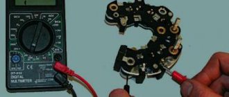
1. Dodas are checked with a universal device. (6 diodes in total) Attach the black “negative” probe to the negative plate, and the positive “red” probe alternately to the three contact terminals of the diodes. The resistance should be 580-620 Ohms.
Attach the red “positive” probe to the negative plate, and the negative “black” probe alternately to the three contact terminals of the diodes. The resistance should be 580-620 Ohms.
Checking the windings of the Lada Kalina generator
1. Check the generator windings with a device. All windings should have approximately equal resistance, without significant deviations. Deviations indicate a break or short circuit.
About the principle of operation of a car generator
The operation of the Lada Kalina generator unit is based on the following principle: an alternating current is induced in the stator winding, which is subsequently transformed into direct current through a rectifier module located on the body of the unit. The generator cover is also equipped with an electronic voltage regulator and a brush holder. The rotor of the device receives torque from the crankshaft pulley. The transmission link is a poly V-belt.
The basic characteristics of the generator set include the following parameters:
- maximum generated current – 85-90 Amperes;
- operating range of on-board voltage – 14.4-15.1 Volts;
- rotation ratio of the motor and rotor – 1:2.4;
- right-hand direction of rotation.
The housing of the unit is held together by pins that tighten the stator with the covers. The mounting sockets of the indicated covers contain bearings, which ensure the ability of the rotor to rotate.
The rear bearing is installed inside the cover with a minimum gap. The front element is equipped with the ability to slide along the surface of the rotor shaft. It is fixed inside the front cover with a slight interference fit, and a pressure plate covers it from the outside.
The back of the device is protected by a plastic casing.
Let's move on to the switching diagram of the generator with the on-board network. The connection diagram is very simple. After turning on the ignition, power begins to flow to the voltage regulator through the battery discharge lamp circuit. When the motor starts, the excitation winding is supplied with supply voltage from three diodes mounted in the rectifier unit.
Using the indicated signal lamp, the generator unit can be checked. If the device is working properly, the lamp lights up when the ignition is on. It goes out when the engine starts.
When this phenomenon is not observed and the lamp continues to shine, the generator set should be diagnosed for the presence of malfunctions.
In some cases, replacement is required, and many are interested in how to remove the generator?
Reasons why the indicator does not light up
It is extremely important to be able to independently find out the causes of the problem, as well as study ways to eliminate it. In fact, there are many reasons why a light bulb fails.
However, you will have to check all the options in order to come to the only correct decision.
As a rule, the initial knowledge of an auto electrician is enough to carry out the inspection. As mentioned above, there are several reasons, but they are divided into two categories: harmless and dangerous.
A dangerous cause that requires immediate repair is a circuit malfunction or breakage. As for harmless reasons, this is a banal light bulb burnout, battery discharge, etc.
Along with this, the same reason can turn from harmless to dangerous
And this is important to understand
Battery discharge
If, at the same time that the battery light does not light up, the dashboard instruments do not turn on or are dimly lit, then this is a clear sign of a low battery. The problem can be “cured” by simply charging the battery.
Actions when charging disappears
The generator on a Kalina with air conditioning has more power than on cars without an air conditioning system. The design and faults are the same. What to do if charging is lost? Don't panic and check immediately:
Voltage regulator. The easiest and most expensive way is to replace it with a known good one. But you can also apply voltage of 12 V and 15 V to check operation. Regardless of whether the regulator is mechanical or electrical, it will behave the same. In the first case, voltage will be supplied to the excitation winding, but in the second - not. Alternator slip rings and brushes. You can use a simple lamp probe to check the contacts. The length of the brushes must be more than 5 mm, otherwise they should be replaced. The integrity of the field winding can be checked with a tester. Moreover, there is no need to remove the generator, just crawl up to the slip rings and check the resistance between them
Please note that they should not short to ground. The condition of the stator winding and diode bridge can be assessed only after dismantling the generator.
Checking and tensioning the generator drive belt
A loose belt and poor condition can be identified by a characteristic “whistle”, especially when starting the engine.
To perform the work, you can remove the right front wheel or install the car on an inspection ditch or overpass.
1. Remove the right side of the engine mudguard.
2. Visually check the condition of the generator drive belt. We apply a force of 98 N (10 kgf) to the belt exactly in the middle between the generator pulley and the engine crankshaft pulley. (You can use the steelyard).
3. To adjust, remove the windshield washer reservoir.
4. Using a 19-mm open-end wrench, unscrew the locknut of the tensioning mechanism.
By rotating the adjusting pin with a socket wrench by 8, we change the tension of the generator drive belt (clockwise we increase the belt tension, and counterclockwise we decrease it).
Excessive belt tension can lead to failure of the front alternator bearing.
5. Check the tension of the generator belt (see above) and, if necessary, repeat the adjustment.
6. After making sure that the belt is tensioned correctly, hold the adjusting pin and tighten the locknut.
7. Install the engine splash guard.
Checking the rectifier unit (diode bridge)
To perform this diagnostic, it is necessary to remove the diode bridge from the Kalina generator; this was described in more detail in previous articles in this section.
Then we connect the tester with the black wire to the negative plate of the block, and the red one in turn to the three contact terminals of the diodes. This way we check all the rectifiers in the block. The values on the device should be in the range from 400 to 800 Ohms. Personally, on my Kalina, during this test, all diodes showed a resistance within 535 Ohms. But the repair instructions from the Third Rome publishing house talk about numbers of 580-620 Ohms. I will say right away that when I rang two serviceable generators, the values specified in the manual were not achieved, although there were no problems with charging, so I personally doubt the accuracy of the data in this instruction.
Then we carry out the same operation, only swapping the contact wires of the multimeter. In this case, the device, with working diodes, will show infinity, that is, its readings will not change: