Once it starts working, the generator begins to produce direct current, but to operate all the devices in the car, as well as to charge the battery, an alternating current is needed (pulsating with a clearly defined frequency).
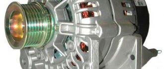
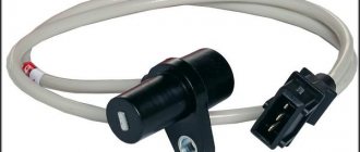
Diode bridge 2110-3701315 “StartVOLT” for VAZ 2110-2172 generators produced by KZATE
It is the conversion of current that the diode bridge of the VAZ 2110 generator, which is also called a rectifier, is engaged in. And although there are many design options, the cars are equipped with three-phase ones, the advantages of which are obvious:
- At the output they create the smallest ripple voltage;
- Three-phase rectifiers are suitable for bridge and half-bridge diodes;
- They make it possible to install an additional capacitor - a current filter.
Design
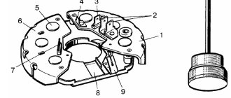
In the original (factory) configuration, the diode bridge of the generator on the VAZ 2110 is a monolithic structure. It is quite reliable, inexpensive, compact, and has, one might say, only one drawback: if one of the diodes burns out, its local replacement is impossible; you need to buy a new factory bridge and install it.
In the event that a check shows that the diode bridge is no longer functioning and needs to be replaced, it is quite possible to assemble it from various diodes. If the factory layout provides four or six diodes, then during self-assembly you can install an additional one.
Many car enthusiasts do this. In addition, as a rule, in the case of self-assembly, diodes are installed not in the factory layout, but a little stronger, so that they do not burn out so quickly.
But since it is impossible to qualitatively test such a rectifier, during “home assembly” you can damage the generator, after which it will be necessary to replace not just a cheap part, but the entire assembly.
How to replace a diode in a generator diode bridge
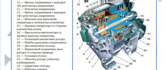
As you know, a car generator is designed to provide power to all electrical equipment in the car when the engine is running. This unit in domestic “tens” consists of many elements that ensure its optimal operation. One such device is a diode bridge. What functions does it perform, what do you need to know about its malfunctions, and how is the diode bridge of the VAZ 2110 generator replaced? You can find answers to these and other questions below.
Causes of breakdowns
As numerous checks show, the main cause of breakdowns is factory. Here, first of all, you need to pay attention to the shell in which the diodes are located. If it is aluminum, it is better not to take such a unit. Much more reliable is steel.
In addition, if the seller does not provide a guarantee, you should be wary. According to reviews on the Internet, the most unreliable diode bridges are made in Belarus.
Step-by-step instructions for repairing the VAZ 2110 generator are located here:
Other reasons:
- Another reason is moisture ingress, which results in oxidation of the space between the diode itself and the housing;
- Contact of oil or other working fluids of the VAZ 2110 on the surface;
- If you reverse the polarity of the battery while lighting or charging, the diode bridge can easily “fly out”;
- You can also suspect that the VAZ 2110’s rectifier is failing if the battery stops charging.
Checking and replacing the diode bridge of the VAZ 2110 generator with your own hands
Once it starts working, the generator begins to produce direct current, but to operate all the devices in the car, as well as to charge the battery, an alternating current is needed (pulsating with a clearly defined frequency).
Diode bridge 2110-3701315 “StartVOLT” for VAZ 2110-2172 generators produced by KZATE
It is the conversion of current that the diode bridge of the VAZ 2110 generator, which is also called a rectifier, is engaged in. And although there are many design options, the cars are equipped with three-phase ones, the advantages of which are obvious:
- At the output they create the smallest ripple voltage;
- Three-phase rectifiers are suitable for bridge and half-bridge diodes;
- They make it possible to install an additional capacitor - a current filter.
Examination
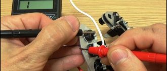
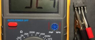
Using a multimeter it is very easy to check the serviceability. Need to:
- Place the positive probe of the multimeter at the positive diode bus;
- Do the same with the negative probe and the “-” diode output;
- This test, if the diode bridge is working properly, should give readings close to infinity. If this is not the case, there is a malfunction and needs replacement;
- Now we swap the probes (put plus to minus and vice versa);
- Let's look at the readings. If the unit is working properly, the readings should be several hundred ohms;
- To check the additional diode, perform the same steps as described above.
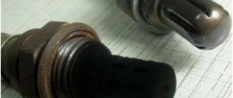
An article dedicated to repairing and replacing the speed sensor is located here:
Video “How to avoid mistakes when replacing the DM in a VAZ 2110”
More clear instructions for replacing the diode bridge in the “Ten” with a description of the main points and nuances are given in the video below (the author of the video is Semyon Pedan).
Let's start with the fact that a diode bridge is an electrical circuit, a chain of diodes designed to convert alternating current into direct current. A faulty diode bridge is one of the main causes of generator malfunction, and is also a powerful consumer that can drain the battery to zero overnight.
A faulty diode bridge can both discharge and recharge the battery, which can result in major electrical problems. The principle of diodes, in addition to converting current from alternating to direct, is the unipolarity of current transmission from the generator to the battery. In other words, a working diode transmits current only in one direction (generator - battery), a faulty diode transmits current in both directions (battery - generator) or does not transmit anything at all. Diodes burn out due to poor contacts or moisture.
Before you start blaming the diode bridge for all your problems, be sure to check the generator brushes and voltage regulator.
To start checking the diode bridge, you need to remove it, fortunately the process is simple. You can also do without removing the rectifier block (diode bridge), but this is very, very inconvenient.
One way to check the diode bridge is to check the on-board system for current leakage (How to check for current leakage?)! If the current consumption in a stopped engine with electrical appliances turned off is 1A per hour or higher, then most likely the problem lies in the diode bridge. The bridge can only be checked more thoroughly when removed.
Replacement
When dealing with any component related to electrical equipment, you need to start by de-energizing the VAZ 2110. So, we proceed according to the algorithm:
- Disconnecting the battery (remove the “-” terminal);
- Remove the pink wire that turns on the generator. To do this, you need to unscrew the nut from the positive bolt;
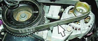
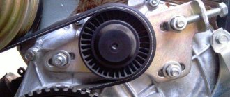
- Loosen the upper and lower nuts, and also unscrew the tension bolt, remove the belt;
- Turn the generator 90° and remove the lower mounting bolt;
- Clean all connections, as well as the rectifier housing itself;
- Clean the inside of the ring very thoroughly;
- Replace the generator diode bridge with a new one;
- Reassemble all parts;
- Check the functionality of the generator.
In order to properly tension the alternator belt, it is recommended that you familiarize yourself with this material:
- Author: ratico19
Rate this article:
- 5
- 4
- 3
- 2
- 1
(6 votes, average: 1.8 out of 5)
Share with your friends!
How to remove the generator diode bridge (rectifier unit)?
- We remove the negative terminal of the battery and disconnect/unscrew the wires going to the plastic casing of the generator.
- Disconnect the wire block “D”.
- Remove the protective rubber cap from the tips of the “+” terminal wires. We unscrew the nut securing these wires and remove them from the generator block.
- Next, remove the black plastic casing of the generator itself. To do this, you need to disconnect the three spring clips located around the perimeter of the block.
- We find the voltage regulator, and use a Phillips screwdriver to unscrew its fastenings.
- We take out the voltage regulator assembly with brushes.
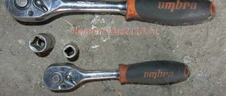
- Take the key to “8” and unscrew the 3 bolts securing the bridge.
- We bend the leads to the stator winding to the side and use a Phillips screwdriver to unscrew the capacitor mount.
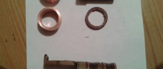
We take out the diode bridge! We unscrew the 2 nuts of the contact bolt with a “10” key. We remove the bushing from the contact bolt and remove the bolt itself from the diode bridge. READY! You can start replacing and checking the rectifier unit (diode bridge)!
Relay regulator
The relay regulator maintains the optimal voltage value in the standard electrical circuit. In fact, it is precisely this that prevents the voltage from increasing to critical values. To carry out the test, start the engine, connect the multimeter and set the “voltage measurement” value.
After this, it is necessary to measure the power supply of the on-board network directly at the battery terminals or at the contacts of the generator itself. The values should be between 14–14.2 V.
Then you need to press the accelerator and take the measurement again.
Note! The readings should not change by more than 0.5 V. Otherwise, this will indicate incorrect operation.
Topic: What goes to the generator exciter wire?
Theme Options
Search by topic
Pointer
Registration 03/25/2011 Address Kaliningrad Messages 92
| Thank you: |
| Received: 0 Sent: 1 |
I measured the blue wire and nothing seemed to be going through it.
Lupo
Registration 06/15/2011 Address Tver Age 36 Messages 230
| Thank you: |
| Received: 5 Sent: 0 |
That's right, the blue wire is needed to excite the generator. When the ignition is turned on, there should be supply voltage. It comes from the dashboard: 12 pin tidy, black 10-pin connector (1 pin) in the ECU box, then to the generator. Look for a cliff.
I confirm
Without this very wire, the gene is excited quite well
But first you need to accelerate.
Pointer
Registration 03/25/2011 Address Kaliningrad Messages 92
| Thank you: |
| Received: 0 Sent: 1 |
Depends on the residual magnetization of the armature and stator.
Well, yes, I agree. I started this recently. And if it stays overnight, he probably won’t get aroused without forced arousal.
Pointer
Registration 03/25/2011 Address Kaliningrad Messages 92
| Thank you: |
| Received: 0 Sent: 1 |
So the problem is in the tidy.
READ How to connect popcorn to computer
Source
Assembly and installation of the generator
- All parts must be thoroughly wiped with a clean napkin before installation.
- When assembling, it is important to orient the generator covers according to the previously made marks.
- The pulley spring washer must be installed with the convex surface facing the nut. The tightening torque of the nut is 39-62 Nm.
- The assembled generator is installed in its place, the belt is put on and tension is applied.
- When all the fasteners are closed and the wires are connected, the engine is started.
One of the most common problems with the BAZ 2110 car is the short-lived service of the steering rack. As soon as characteristic knocking noises appear when turning the steering wheel, it’s time to replace or service the rack.
The VAZ 2107 stove is famous for its good heat dissipation. But over time we have to change it or repair it. You can do this labor-intensive work yourself. You just need to follow the instructions below.
Additional adjustment of the spark plug gap guarantees faster engine starting. How to choose the optimal spark plug gap gauge and how to properly adjust the spark plug gap?
Repairing a generator on a VAZ 2110 car with your own hands is quite possible. You can either partially repair the element or completely replace it. It all depends on the specific situation and the degree of wear of the device.
According to the operating manual, a routine check of the condition of the generator should be carried out every 50 thousand kilometers. But this is provided that the device is working properly.
Device diagram
Additional testing of generator components faults
The stable operation of this device can be affected not only by the DM and the relay regulator, but also by the electric rotor and stator windings, brushes and capacitor. If the first measurements do not reveal any malfunctions in the operation of the main generator components, then proceed to additional testing of the generator components.
Generator winding testing
This type of measurement is carried out on a dismantled and disassembled generator. You will need to separately check the serviceability of the rotor and stator windings. The meter is set to ohmmeter mode at a value of 200 Ohm.
The main stages of monitoring the electric rotor and stator windings:
- Measure the resistance value on the rotor windings. For this purpose, probes are connected to the outputs of the windings. The normal value is above 5 ohms, if less than 1.9 ohms, there is a turn short on the rotor. Most often, the electrical circuit breaks in the connection areas between the rotor winding and the ring. It is possible to determine the malfunction by moving the wire in the soldering area with a probe. Alternatively, integrity may be compromised here.
- Carefully inspect all connections. It is possible that dark and damaged wire insulation will be detected, which is a consequence of a break and short circuit.
- We call electrical circuits to determine the short circuit on the housing. To do this, the first probe is brought to the rotor shaft, and the second to any ring. If the winding is working properly, the ohmmeter reading will go off scale. If the resistance is low, this winding must be rewound. In this case, perfect balancing must be maintained.
- Before checking the stator, a visual inspection is performed, paying attention to all kinds of external damage to both the housing and the insulator, as well as the places where the wires from the short circuit are burned.
- If a defect is detected, the stator is sent for rewinding.
- If no external abnormalities are found on the stator, examine it with a multimeter.
- The stator must be disconnected from the generator and removed.
- The multimeter is set to resistance control mode. Initially, the probes are installed on the 1st pair of terminals. Then they test a pair of windings “1–3”, and then “3–2”. If the analog multimeter needle goes off the scale, the windings will need to be rewinded.
- To check the generator for the absence of a short circuit between the turns and on the housing. The first probe is connected to the terminal, and the second to the body. If the windings are short-circuited, the multimeter on the scale will show a lower resistance value than on the working ones.