Exhaust manifold VAZ 2110
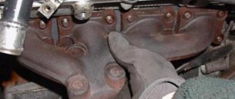
When the car engine is running, smoke and the smell of gas may appear under the hood of the car. The reason may be that the exhaust manifold has burnt out. On a VAZ 2110, replacing the exhaust manifold is associated with metal burning. In this case, it is not recommended to delay replacing it. Since further operation of the machine may cause big problems. Replacing the exhaust manifold of a VAZ 2110 can easily be done with your own hands. Burnt holes are almost impossible to visually examine. When the engine is running, the hood should be open. Exhaust gases will escape, not into the exhaust pipe, but will whistle through these burnt holes. Gases can escape under the bottom of the machine, since the material burns out mainly in those places where the pipe is bent.
Exhaust manifold VAZ 2110 - replacement and repair
In some cases, when starting the engine, smoke and a gas smell may appear from under the hood. Most often, this indicates that the exhaust manifold may have burned out, and on the VAZ 2110 it needs to be replaced, since the metal has burned out. And here you should not delay replacement or repair, since all these problems can adversely affect the operation of the engine as a whole. You can replace the part yourself; there is nothing difficult here.
Usually the burnout site is practically invisible, but with the engine running you need to open the hood of the car. And then consider where the exhaust gases come from; if they pass with a whistle, then they go past the exhaust pipe, and go through the burnt-out place.
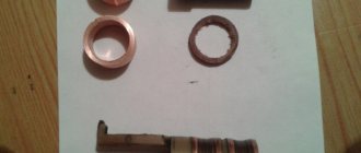
Gasket - manifold
The routing of the manifolds must be checked by the contractor for the compressed air supply project.
The installation of collectors is provided for by the energy supply project contractor.
When laying collectors with sheet pile walls in slightly saturated soils, it is recommended to lower the water level using wellpoints.
When laying collectors under urban buildings, as well as under unfavorable geological conditions and significant depths, the open trench method is not applicable. In these cases, excavation methods are used without opening the overlying soil.
When laying collectors, gravity channels and other pipelines at great depths, work is carried out in deep workings. For such workings, it is necessary to construct mines, which are a deep, braced pit (usually of a circular cross-section) with a diameter of up to 6 m, running from the surface of the earth to the mouth of the underground working. Structures are erected above the mine shaft to ensure the lifting and lowering of people, equipment and materials into the workings, as well as the release of developed soil to the surface of the earth.
If it is planned to lay a compressed air manifold (steel pipe from 4 and above), then first of all it is secured to the supporting structures, and then the pipe blocks are installed.
In the practice of laying irrigation collectors under railway tracks, there are cases where, in order to effectively seal joints of reinforced concrete pipes with a diameter of 450 to 1050 mm, special rubber gaskets with protruding ridges were used, allowing some movement in the joints without compromising their tightness (Fig.
| Types of channels for underground communications recommended for use in permafrost areas. |
It is possible to recommend laying critical collectors in reinforced concrete passage galleries together with other pipelines and cables.
Work on laying collectors using the panel method must be carried out according to specially developed projects.
Sometimes, when laying collectors and highways, as well as when constructing structures in aquiferous soils, fencing of trenches and pits is carried out using a solid wall of piles; such piles are called sheet piles.
If it is technically and economically feasible, the installation of large diameter collectors (800 mm or more) can also be done at great depths using the tunnel (panel) method.
One of the causes of accidents is the laying of manifolds for discharge from safety valves without observing slopes and with the presence of bags. The latter, when filled with liquid, create back pressure and resistance to valve operation.
Such areas are bypassed, collectors are laid at great depths in more reliable soils using the shield tunneling method, or pumping stations are installed. The locations of pumping stations should be determined taking into account sanitary requirements and the layout of the locality.
When developing refinery and petrochemical plant projects, it is envisaged to lay steam collectors with three or four parameters. Steam at a pressure of 11 5 MPa is used only in petrochemical plants; it is supplied to turbines, which drive compressors in pyrolysis plants. Steam at a pressure of 2 5 - 4 0 MPa is used for turbine drive of compressors and for heating products above 160 C, if it is not practical to carry out fire heating or heating using intermediate coolants.
Self-replacement
Replacing the exhaust manifold of a VAZ 2110
- the car needs to be driven into the garage;
- hang a lamp with a safety light under the hood;
- before starting repairs, antifreeze must be drained from the tank;
- disconnect the battery terminals;
- take it out;
- put on a rack;
- disconnect the vacuum booster hose from the receiver;
- also disconnect the hoses of the electric pneumatic valve cover and the ramp pressure regulator;
- disconnect the chips of the throttle sensor, idle air control;
- disconnect the throttle valve cable;
- loosen the clamp on the air supply hose to the air flow sensor housing;
- disconnect it;
- loosen the clamps for attaching the hoses to the throttle pipe and ventilation of crankcase gases on the cylinder head cover;
Replacing the cathode collector for a VAZ 2110
- remove the hoses in pairs;
- loosen the crankcase ventilation hose clamp;
- remove it from the throttle assembly;
- In the same way, carry out further work with the coolant inlet and outlet hoses.
Note. Use a 13mm socket to make the work easier, unscrew the 2 nuts from the throttle assembly from the studs. The throttle assembly is attached to the receiver.
- loosen the clamp;
- disconnect the adsorber purge hose;
- remove the throttle assembly;
- remove the sealing gasket.
Note: these nuts must be unscrewed using a number 13 wrench.
The receiver must be removed together with the throttle assembly. In addition, it is necessary to disconnect all inlet and outlet hoses and idle speed sensor chips from the assembly. Carefully check to make sure that all fastenings are completely loosened.
Note: it is recommended to remember all the attachment points; you can use threads of different colors. To prevent incorrect connections during assembly.
Note: place the parts in a container so that during assembly you do not have to look for missing spare parts.
Unscrew the 2 nuts for attaching the fuel supply and outlet pipe bracket to the receiver. The same - 1 nut for fastening the receiver to the bracket, 5 pieces for fastening to the intake manifold. Remove the receiver, remove the gasket.
Disassembling the VAZ 2111 engine
Place the washed and cleaned engine on a disassembly stand and drain the oil from the crankcase. Disassembly is carried out in the following order
4- sealing gasket; 5 - receiver; 6 — exhaust pipe of the engine cooling system; 7 — hose clamps; 8 — supply pipe of the coolant pump; 9 — throttle pipe heating hoses; 10 — inlet pipe hose
Disconnect from the throttle pipe (see Fig. 1.) hoses 9 for inlet and outlet of coolant, as well as the crankcase ventilation hose at idle. Remove the throttle pipe with the gasket by unscrewing the nuts securing it to the receiver.
Remove the fuel supply and drain pipes by disconnecting them from the injector rail, the fuel pressure regulator and from the bracket on the receiver. Remove the vacuum hose by disconnecting it from the connections on the receiver and fuel pressure regulator.
Remove the receiver 4 (Fig. 2.) with the gasket 3 and the fuel line bracket by unscrewing the nut securing the bracket 6 to the receiver and the nuts securing it to the inlet pipe 2.
Disconnect the wiring harness from the injectors and remove the injector ramp 1 (Fig. 3.) with pressure regulator 2 by unscrewing the two bolts securing it to the intake pipe.
On the left side of the engine, remove the high voltage wires, ignition module and knock sensor. Using wrench 67.7812.9514, remove the spark plugs, coolant temperature sensor and oil pressure sensor from the cylinder head. Unscrew the temperature sensor, which is part of the engine management system, from the outlet pipe of the cooling jacket.
tension bar; 5 - generator; 6 — generator mounting bracket; 7 — generator drive belt
Remove the tension bar 4 (Fig. 4.) and the generator drive belt 7. Remove the generator 5 and its mounting bracket 6. Lock the flywheel with clamp 67.7820.9526 (see Fig. 5), unscrew the bolt securing the generator drive pulley and remove the pulley.
1 — front protective cover; 2 — rubber seal; 3 — toothed belt; 4 — camshaft pulley; 5 — crankshaft toothed pulley; 6 — spacer washer; 7 - tension roller
Remove the front cover 1 (Fig. 6.) of the timing belt. Unscrew the nut securing the tension mechanism. Loosen and remove toothed belt 3. Remove tension roller 7 with spacer washer 6.
Holding the camshaft pulley 4 from turning with tool 67.7811.9509, unscrew the pulley mounting bolt, remove the pulley and key. Remove toothed pulley 5 from the crankshaft.
Remove the coolant pump mounting bolts. Unscrew the bolt and nut securing the rear toothed belt cover and remove it. Remove the coolant pump with the gasket from the socket in the cylinder block.
Remove the exhaust manifold with gaskets.
Disconnect the hoses from the thermostat and remove it. Remove the coolant pump inlet pipe and the coolant jacket outlet pipe with gasket.
Using tool A. 60312 (Fig. 7.), remove the oil filter with gasket. Disconnect the crankcase exhaust ventilation hose from the pipes on the cylinder head cover and on the cylinder block. Remove the oil level indicator.
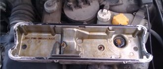
Remove the cylinder head cover. Unscrew the cylinder head bolts and remove it complete with the camshaft. If necessary, disassemble the cylinder head.
Turn the engine over with the crankcase up and remove the oil sump 5 with gasket 4. Remove the receiver 3 and the oil pump 1.
Unscrew the nuts of the connecting rod bolts, remove the connecting rod caps and carefully remove the pistons with connecting rods through the cylinders. Lock the flywheel with clamp 67.7820.9526 (Fig. 5), unscrew the flywheel mounting bolts, remove the bolt washer and the flywheel from the crankshaft
Remove the crankshaft rear oil seal holder with gasket
Lock the flywheel with clamp 67.7820.9526 (Fig. 5), unscrew the flywheel mounting bolts, remove the bolt washer and the flywheel from the crankshaft. Remove the crankshaft rear oil seal holder with gasket.
Remove the main bearing caps along with the lower bearings. Remove the crankshaft from the bearing housings, and then the upper bearings and thrust half-rings from the middle support.
Ramp
Replacing the cathode collector on a VAZ 2110
The ramp is removed as an assembly with the fuel pressure regulator:
- It is necessary to disconnect the vacuum hose from the regulator.
- Using 2 open-end wrenches 17, unscrew the fittings securing the gasoline supply pipes to reduce pressure.
- Disconnect the ramp voltage connector.
- Using a screwdriver, unscrew the screw of the bracket for fastening the gasoline supply and outlet pipes and disconnect it.
- Using a No. 5 hexagon, unscrew the 2 screws for fastening the ramp.
- Pull the ramp in the axial direction of the injector from the seat, remove the ramp towards the left side of the hood.
Note: follow the direction of travel of the vehicle.
Replacement cathode collector for VAZ 2110
- Unscrew the nut from the left intake manifold bracket and loosen the lower bolt.
- Remove the bracket from it.
- Perform the same operation with the right bracket and remove it.
- Unscrew the 2 nuts from the eye stud.
Removing the eye
- Unscrew the 3 nuts from the receiver bracket and remove it.
- Carefully remove the bushing from the intake manifold stud.
- Disconnect the exhaust air intake pipe and remove it from the lower intake air studs.
- Unscrew the top nut and loosen the bottom nut a little on the bar.
Note. It holds the antifreeze pump tubes for cooling. The bar at the bottom has a through slot; carefully remove it.
Replacement cat collector for VAZ 2110
- The intake manifold is mounted on studs, so you need to unscrew one nut on top and 2 on the side. To remove the exhaust manifold, you need to unscrew an additional 2 nuts. You need to carefully inspect the connection point, since 2 gaskets are installed between the manifold and the block head.
Note. When dismantling the intake manifold, pay attention to the gaskets. If the gasket burns out, antifreeze can get into the cylinder block. There may be holes drilled by antifreeze on the head of the blocks, and there may also be holes in the gasket.
Replacement cat collector for VAZ 2110
- Antifreeze may leak into valves and cylinders. In this case, you need to remove it from there using a syringe. Unscrew the spark plugs (see Replacing spark plugs on a VAZ 2110 on your own) and crank them with the starter to remove any antifreeze that gets there. If grooves are found on the surface, the collector must be replaced.
- At the bottom, the exhaust manifold is attached to the exhaust pipe. Then it is connected to the exhaust pipe. Unscrew the three bolts and disconnect the pipe. Remove the collector. You need to unscrew them from the inspection hole and first tap the heads. Use a metal brush to clean the nuts and threads.
- During assembly, replace all gaskets with new ones one by one. It is advisable to tighten the nuts during assembly using a special wrench. Also replace the injector O-rings with new ones.
Gaskets are sold in sets, the cost of one is from 300 rubles. The cost of the exhaust manifold is 1,700 rubles. If the replacement is carried out at a service station or car service station, the repair will cost around 3,500 rubles plus the cost of a set of gaskets and a manifold. When doing your own repairs to replace the exhaust manifold, you must carefully and scrupulously read the instructions. Also view video clips and photos.
Note: photographs must be arranged in order of work. As repair processes are completed, fold them in reverse order. Once you've finished disassembling, turn the stack of photos over. Reassemble in reverse order. Before assembly, the nuts must be lubricated with graphite thread lubricant, and the threads of all bushings must also be lubricated. Thoroughly clean the installation areas of the gaskets from inclusions and foreign contents.
By doing the work yourself, you can save a lot of money, because the price of repairs in special workshops and service stations is very high and not everyone can afford to pay the cost.
Add to cart Add to cart
Availability in stores: > 10 pcs.
How to extend gasket life
Although replacing the exhaust manifold gasket is inexpensive and can be done successfully in your own garage, who wants to waste their time on it? It's better to let it serve longer. And to extend its service life, listen to the following tips:
- monitor the condition of the cooling system, check the level of antifreeze (antifreeze) to prevent engine overheating;
- use only high-quality fuel;
- check the tightness of the connection between the cylinder head and the exhaust manifold;
- If you find that the integrity of the gasket is damaged, do not wait until it burns out completely, replace it;
- When buying an exhaust manifold gasket, choose a quality product from well-known manufacturers.
In this article we will discuss the symptoms when the exhaust manifold gasket has burned out. For an exhaust device, the gasket is one of the main parts on which the entire correctness and accuracy of the exhaust system will depend.
If the manifold seal is not replaced in a timely manner, the safety conditions for operating the vehicle are greatly reduced.
In general, a manifold is a device designed to remove exhaust gases from a car engine. The second function of the collector is to improve the filling of the working chambers and enhance the ventilation of the working space. All operation of the exhaust device is carried out at elevated temperatures and high gas pressure.
This element is attached directly to the head ( cylinder head
) and the other side is in contact with the exhaust pipe or converter. The most important task of the exhaust manifold gasket is to prevent exhaust gases from entering the valve space. These gases, in turn, can cause fire of parts or elements of the power unit.
Symptoms of a blown exhaust manifold gasket
The following can be distinguished: exhaust gases begin to flow into the car interior or their smell is felt; the car engine begins to start poorly; Strange sounds appear in the engine compartment. If these ailments are detected, you should begin to inspect the exhaust system. The collector itself is made of high-strength austenitic steel.
In this regard, burnout and replacement of the collector is quite rare. The main reason for the breakdown of the collector itself is drops of water falling on its hot surface, which leads to the formation of cracks in it.
The weak link of this durable and reliable element is the gaskets. Wear of the manifold gasket occurs mainly due to: poor quality of the material or very long operation under increased loads.
Manifold gaskets are now made from steel-reinforced, durable asbestos. However, even such a durable material is susceptible to destruction. The process of replacing the exhaust manifold gasket is not at all difficult.
Experts even recommend replacing the gasket after some time, without waiting for it to fail.
We carry out the following procedures:
- 1. Open the hood of the car;
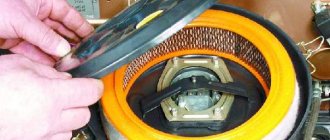
- 2. Remove the air intake. Then remove the carburetor. Under these engine elements is the exhaust manifold;
- 3. Remove the thermal shield. It covers the collector;
- 4. Unscrew two nuts on each cylinder that secure the manifold;
- 5. Unscrew a couple of bolts from the exhaust pipe;
- 6. Remove the manifold;
- 7. There should be an old gasket or remains of it on the cylinder head;
- 8. We clear all the space for a new gasket;
- 9. Clean everything until it shines;
- 10. After cleaning, apply a graphite-based lubricant to the area;
- 11. Now install a new gasket;
- 12. Reassemble everything in reverse order.
- 1. The pressure on the turbine begins to decrease;
- 2. When driving at high speeds and under load, black smoke appears in the exhaust;
- 3. When driving on the highway, you feel increased fuel consumption;
- 4. It may start to whistle at certain speeds.
As you can see, the symptoms can significantly affect the driving characteristics of the car. Therefore, you should not delay replacing a burnt gasket. In this article, we discussed the main symptoms that the exhaust manifold gasket has burned out. I would like to add the word “may” to all the symptoms described in the article, since they may not appear, or they may appear in a slightly different way.
Symptoms that the exhaust manifold gasket has burnt out. Full list and action plan »
Self-replacement
- the car needs to be driven into the garage;
- hang a lamp with a safety light under the hood;
- before starting repairs, antifreeze must be drained from the tank;
- disconnect the battery terminals;
- take it out;
- put on a rack;
- disconnect the vacuum booster hose from the receiver;
- also disconnect the hoses of the electric pneumatic valve cover and the ramp pressure regulator;
- disconnect the chips of the throttle sensor, idle air control;
- disconnect the throttle valve cable;
- loosen the clamp on the air supply hose to the air flow sensor housing;
- disconnect it;
- loosen the clamps for attaching the hoses to the throttle pipe and ventilation of crankcase gases on the cylinder head cover;
- remove the hoses in pairs;
- loosen the crankcase ventilation hose clamp;
- remove it from the throttle assembly;
- In the same way, carry out further work with the coolant inlet and outlet hoses.
Note. Use a 13mm socket to make the work easier, unscrew the 2 nuts from the throttle assembly from the studs. The throttle assembly is attached to the receiver.
- loosen the clamp;
- disconnect the adsorber purge hose;
- remove the throttle assembly;
- remove the sealing gasket.
Note: these nuts must be unscrewed using a number 13 wrench.
The receiver must be removed together with the throttle assembly. In addition, it is necessary to disconnect all inlet and outlet hoses and idle speed sensor chips from the assembly. Carefully check to make sure that all fastenings are completely loosened.
Note: it is recommended to remember all the attachment points; you can use threads of different colors. To prevent incorrect connections during assembly.
Note: place the parts in a container so that during assembly you do not have to look for missing spare parts.
Unscrew the 2 nuts for attaching the fuel supply and outlet pipe bracket to the receiver. The same - 1 nut for fastening the receiver to the bracket, 5 pieces for fastening to the intake manifold. Remove the receiver, remove the gasket.
1 Topic by Aleksandr.21124 2016-04-28 16:31:36
- Aleksandr.21124
- Brother-in-law
- Inactive
- Registration: 2014-08-11
- Messages: 392 Thanks : 169
- Car: VAZ 21124
Topic: Installing a 4-1 or 4-2-1 exhaust manifold on a VAZ.
Exhaust manifold (Spider)
Most of the exhaust losses occur in the exhaust manifold. In sports and tuning, the standard manifold is replaced with a so-called “spider”, which differs in the shape and order of connection of the exhaust pipes with the exhaust windows. “Spiders” come in “short” and “long”. If we take a 4-cylinder engine, then the “long” pipe diagram is built according to the formula 4-2-1, and the “short” one is 4-1. The “long” spider has a 2-1 coupling, the “short” one has a more complex geometry.
The 4-1 manifold provides additional power only in a very narrow rev range, above 6000 rpm, and is usually used for high-boost engines with wide timing camshafts, that is, sports cars. Modification 4-1 is suitable for engines with high afterburner, speed range from 6 to 10 thousand per minute. Typically, these “spiders” are installed on engines with camshafts with a phase of more than 285 degrees.
4-2-1 manifolds are suitable for amateur tuning, as they provide a certain increase in power and torque over a fairly wide speed range. It is believed that short versions of the 4-2-1 model are effective at revolutions above 4500 per minute, and long ones at average speeds from two and a half to four thousand per minute. The physics of how parts work is complex, and without delving into the weeds, we’ll simply answer the question: how many horses will arrive? Few! For VAZ engines it is usually 3-5%, and even if the intake is modified - no more than 7% (this is generally a difficult maximum to achieve). In a direct-flow system, intermediate straight pipes of increased diameter and resonators of reduced resistance are also used. Instead of rigid connections, “corrugations” (bellows) or ball joints are often installed. The latter do not create parasitic resonance frequencies, but are short-lived.
The movement of exhaust gases in the exhaust pipe is an oscillatory process that can be experimentally coordinated with the oscillatory process of movement of the combustible mixture in the suction tract in such a way as to improve the cleaning of the cylinder from exhaust gases and its filling with a fresh mixture. The pressure in the exhaust pipe is subject to sharp fluctuations throughout the entire exhaust period. At the first moment after the opening of the exhaust valve, combustion products rush into the exhaust pipe at a very high speed, exceeding the speed of sound. The rapid removal of 50% of combustion products entails the formation of a vacuum in the cylinder, which can reach up to 0.5 kgf/cm2. In the same way, periods of low pressure are formed in the exhaust pipe.
Experiments with exhaust pipes have proven that the length of the pipe does not affect the efficiency of cleaning the cylinder in the first stage of the exhaust process, but with increasing pipe length, within certain limits, the duration of the period during which the vacuum is maintained increases.
With a change in rotation speed, the period of low pressure in the exhaust system not only changes in duration and magnitude of the vacuum, but also shifts along the angle of rotation of the crankshaft. Therefore, each engine operating mode corresponds to a certain optimal length of the exhaust pipe.
There are two processes in the exhaust system of an internal combustion engine. The first is the gas flow through the pipes, damped to one degree or another. The second is the propagation of shock waves (sound) in a gaseous environment.
Both processes affect the cylinder filling ratio. With the first one everything is simple and clear. High resistance to gas flow (plug the exhaust pipe!) will cause a decrease in the quality of purging and loss of power. It is absolutely clear that the shorter and larger the diameter of the pipe, the lower its flow resistance. In real life, for a one and a half liter engine operating at speeds no higher than 8000, a diameter of 45-50 mm with a length of 3-3.5 meters is sufficient. A further increase in diameter does not cause a significant decrease in dynamic resistance.
If we turn to foreign practice, it turns out that specialists in the field of exhaust systems can get an increase in power of more than 12-15 horsepower. This significant increase in power is obtained by replacing all parts of the exhaust system (pants, catalytic converter, resonator, tip).
Athletes get a big boost, but due to the fact that their hands are not tied by exhaust volume - a sportbike has a sound pressure of about 120 decibels (the officially permitted limit is 100 dB).
A group A muffler can give an increase of 30 horsepower, but driving around the city will be impossible. By the way, any serious intervention in the exhaust system requires adjustment of the power system. Based on this, tuning a 16-valve engine through the exhaust gas system is one of the most important things in its improvement.
Features of the VAZ 2112 control unit
The ECU is located under the dashboard console and controls the fuel injection system. Its task is to process information from various sensors, control systems that affect the toxicity of exhaust gases emitted by the car and the performance of the car during operation. Information received by the controller indicates:
Rotation speed and crankshaft position. Engine air mass flow. Oxygen content in the exhaust gases. Coolant temperature. Presence of detonation in the engine. Throttle position. Voltage in the vehicle's on-board network. Vehicle speed. Camshaft position in a sequential fuel injection system. Turn on the air conditioner, if present.
After receiving the information, the VAZ 21124 engine control unit controls the systems and devices:
- Heat dissipation. Controls the operation of injectors and electric fuel pump.
- Ignition system.
- Adsorber for the gasoline vapor recovery system (when installed on a car).
- Engine cooling fan.
- Idle speed regulator.
- Air conditioning compressor clutch.
- Diagnostic system.
The VAZ 21214 engine control unit includes output circuits - injectors, relays and other devices by connecting them to ground through the controller output transistors. The exception is the fuel pump relay circuit. Only the voltage of +12 V is supplied to its winding from the controller. The controller is equipped with a built-in diagnostic system. With its help, he recognizes malfunctions in the operation of devices and systems and warns the driver about them. To do this, a “CHECK ENGINE” warning lamp is installed in the car. In addition, it stores diagnostic codes that indicate areas of failure, which helps technicians make subsequent repairs. The photo shows a diagram of the fuel injection system.
Fuel injection system
In the diagram, position 11 is the controller.
Main devices of the VAZ 2112 engine control unit
The product has three types of memory:
The first RAM or random access memory. This is a kind of “scratchpad” of the controller. It is used by the microprocessor of the control unit for temporary storage of measured parameters to obtain intermediate information and for calculations. The microprocessor can, if necessary, enter data here and then read it. The RAM chip is mounted on the printed circuit board of the unit. This volatile memory is for maintaining uninterruptible power supply.
There are distribution fuel injection systems of this type:
- With feedback. In this case, an oxygen concentration sensor, otherwise called a lambda probe, is installed in the exhaust system; it provides feedback and a neutralizer. In the exhaust gases, the sensor monitors the concentration of oxygen, and the ECU maintains the ratio of fuel and air based on its signals to ensure efficient operation of the converter. In systems that comply with Euro-2 standards, one oxygen sensor is used, installed before the converter. In systems with Euro-3, there are two oxygen sensors mounted: one before, the other after the converter.
- For engines in which the injection system does not have feedback, an oxygen concentration sensor and a neutralizer are not installed, and the CO concentration in the exhaust gases is adjusted by a CO potentiometer. In this system, a system that provides fuel vapor recovery is also not used.
- It is possible that the injection system does not have a CO potentiometer, then the CO content is adjusted using a diagnostic tool.
- There are phased and sequential distributed fuel injection systems. In the first case, distributed injection has a VAZ 2112 engine control unit with 16 valves. It is additionally mounted with a phase sensor, which determines the moment when the compression stroke in the 1st cylinder ends, and fuel is supplied by injectors to the cylinders in the same sequence as the ignition in the cylinders is turned on (1-3-4-2).
Composition of the output unit
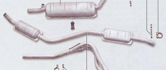
The exhaust system for a VAZ 2110 car consists of the following elements:
- Exhaust manifold;
- Lambda probe;
- Receiving type pipes;
- Neutralizer;
- Two mufflers: main type and additional.
Not all exhaust components are disassembled; some parts, such as the converter, as well as both mufflers, are replaced entirely.
Description of individual components
To make the structure of such an element as the discharge system clearer, it is necessary to give a detailed description of all components:
- Neutralizer. A unit designed for effective purification and suppression of emissions of harmful substances into the environment. When driving, a car produces substances such as non-combustible hydrocarbons, oxide compounds of nitrogen and carbon. The work of this system is aimed at eliminating them. The design itself is a combination of two ceramic-type components. The surface of these components is coated with special afterburning catalysts, which include rhodium, palladium and platinum. These substances make it possible to purify exhaust gases emitted into the environment by almost 100%;
- Lambda probe. It is a special sensor whose task is to control the composition and amount of fuel that enters the engine. The lambda probe thereby controls the purifier. If the lambda probe does not work properly, then the entire output assembly will quickly become unusable, after which it will have to be replaced;
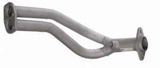
- Reception pipe. Designed for forced removal of exhaust gases from the cylinders of a power unit. The pipe is made of stainless steel, and its fastening to the collector is carried out using special pins, of which there are four in total. The studs guarantee reliable fastening of the two outlet pipes and the element. In order to combine the exhaust pipe and the neutralizer, as well as an additional muffler, hinged fasteners are used;
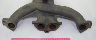
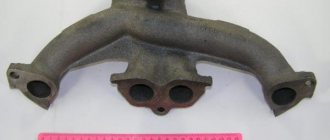
- An exhaust manifold. A component that is cast from pure cast iron. The manifold is secured with four studs in the exhaust pipe. Heat-resistant gaskets reinforced with metal are installed between the manifold and cylinder heads.
- Silencers. Necessary for effectively suppressing the exhaust rate of burnt gases. This is necessary in order to significantly reduce the noise level in a type of transport such as the VAZ 2110. The distribution device in this part of the unit is carried out as follows: the additional one is followed by the main one. These two components are connected to each other by clamps and sealing rings and are covered with a special casing on top.
Nuances of operation
There are some points that need to be taken into account when operating the VAZ 2110 system:
- Under no circumstances should the vehicle be refueled with leaded fuel, as this will cause damage. It is very sensitive to lead compounds;
- When operating a VAZ 2110 car, you also need to monitor the proper, precise operation of the ignition, since its poor-quality operation leads to the neutralizing part being removed from its working condition. Fuel that does not burn when a spark passes during ignition enters the converter and burns out there. For this reason, the ceramic coating of the component quickly deteriorates;
- Frequent malfunctions will sooner or later lead to complete or partial blockage of the output system, in turn to the failure of the engine and its repair or replacement will be required.
Troubleshooting
The operation of a machine is always associated with the occurrence of malfunctions in parts and mechanisms. If some parts become unusable, then they need to be replaced or repaired yourself.
To replace the additional muffler in the exhaust unit:
- unscrew the two bolts that secure the clamp, for this you need a 13mm wrench;
- remove the clamp itself;
- remove the ring;
- disconnect the additional suspension cushions;
- remove the unit.
After this, a replacement is made, it is mounted in place in the reverse order. These are basic troubleshooting repair steps.
In addition to replacing standard faulty components with the same ones, but only new ones, you can modify individual components of the exhaust system, or tune the entire assembly.
If you find an error, please select a piece of text and press Ctrl+Enter.
Where is the VAZ ECU located and the interchangeability of control units
First of all, to determine the type of control unit, you need to find its installation location in the car. To do this, you should study the manual. As an example, let's look at the VAZ 2108 - 2115. On these cars, the ECU is located in the passenger compartment, on the front right, slightly below the glove compartment.
By the way, this information is also useful for computer diagnostics, since you need to know where you can connect to the diagnostic connector installed in various places on a particular model.
As for the units themselves, VAZ 2108 - 2115 of different years of production have different ECU models. For example, the most popular ECU January 4 was installed on early models of injection engines with central injection into the intake manifold.
Version January 5 - 6 are ECUs with distributed injection, but without oxygen sensor support. The January 7 control unit has appeared on cars since 2007, supports all sensors, and effectively controls the engine.
Let us also add that in addition to January, different generations of GM units were actively used at VAZ, being an analogy of January 4 - 7. The same can be said about Bosch or Itelma ECUs. Taking into account all the features, interchangeability is possible, but you need to select analogues that are suitable for the class, version, number of supported sensors, etc.
Composition of the output unit
The exhaust system for a VAZ 2110 car consists of the following elements:
- Exhaust manifold;
- Lambda probe;
- Receiving type pipes;
- Neutralizer;
- Two mufflers: main type and additional.
Not all exhaust components are disassembled; some parts, such as the converter, as well as both mufflers, are replaced entirely.
Exhaust system of VAZ 2110
The main reasons for replacing the catalyst gasket
One of the main reasons for catalytic converter failure is that the exhaust channels become clogged. The formation of plugs leads to the deposition of soot, soot, and other solid deposits. Sources of clogging can be:
- low quality fuel;
- the use by the owner of the technical equipment of all kinds of chemical additives in the combustible mixture (these reagents only have a detrimental effect on the performance of the fuel system);
- possible mechanical damage to the housing or internal connections;
- long-term operation without replacement or prevention;
- faulty engine ignition system;
- unstable operation of the oxygen sensor, due to which the combustible mixture is lean or enriched, which also has an extremely detrimental effect on the performance of the entire system.
How do sellers determine the price?
Manifolds for the VAZ 2110 are sold in many places in Russia. Their prices vary widely. When determining the cost, sellers usually take into account the following:
- What condition is the auto part in?
- Which company made the part? How popular and reliable is it?
- What is the level of competition in the sales region?
- Is the spare part original?
- Are there any promotions currently running?
- What type of auto part?
- Is delivery required, how and where?
Each store adheres to a certain pricing policy. Some companies give discounts to regular customers and organize profitable promotions for various holidays.
Exhaust manifold for VAZ 2110
Causes of malfunctions
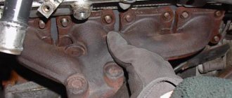
The key factor that causes 90% of exhaust manifold malfunctions on VAZ 2114 cars is high temperature and poor quality materials from which the parts are made. During operation, the steel repeatedly heats up and cools down, which leads to the appearance of cracks in the body. This is a common occurrence for VAZ cars older than 7-8 years.
Auto repair shops offer crack welding services using argon welding. However, for a number of reasons, this activity is useless for cars older than 7 years.
1) Just removing and installing the exhaust manifold will cost about 2.5 thousand rubles. Taking into account the work of the welder and other actions, the cost of repairs can be 4-5 thousand rubles. If you do the work yourself, buying a new part will cost less.
2) Welding, even argon welding, disrupts the structure of “tired” metal. A boiled part rarely lasts longer than a year, after which new holes appear. The older the car, the faster the problem returns, and the collector has to be removed again.
If the car is older than 8 years and there are problems with cracks in the manifold, it is better to remove the part and replace it with a new one.
Exhaust manifold (spider) 4-1 VAZ 2110, 2111, 2112 16cl Stinger
By installing a tuning exhaust, an increase in car power is achieved.
Characteristics:
- Diameter 51mm
- Barrel diameter 120mm
- Barrel length 480mm
Applicability:
- VAZ 2110
- VAZ 2111
- VAZ 2112
It's easy to place an order on our website. Simply add the selected items to your cart, then go to the Cart page, check that the items you ordered are correct, and click the “Checkout” or “Quick Order” button.
The “Quick Order” function allows the buyer not to go through the entire ordering procedure on their own. You fill out the form, and after a short time the store manager will call you back. He will clarify all the conditions of the order, answer questions regarding the quality of the product and its features. It will also tell you about payment and delivery options.
Spare parts and tools
Before you replace a leaking or possibly clogged radiator, you need to choose a new one. Here you have space, it is quite possible that you will want a copper, DAAZ or Priorovsky one. But try to decide for yourself, look at reviews of different models on the forums, and only then buy.
Pay attention to the condition of the pipes; it is quite possible that they also need replacement. You will need more clamps, try not to limit yourself to the three recommended, as you know, a supply will not hurt.
You will need a Phillips screwdriver, preferably a short one
And also - tweezers, without them it is not easy to install the latches.
You will need a Phillips screwdriver, preferably a short one. And also - tweezers, without them it is not easy to install the latches.
Delivery by transport company
Delivery by one of the transport companies with a representative office in your city. Delivery time: 2-10 days depending on the distance of your locality from Togliatti. The most convenient and fastest way to deliver orders of different sizes. Delivery cost from 250 rub. depending on weight and delivery distance.
Orders are sent by transport companies based on 100% payment for the order. Dispatch by transport companies PEK, KIT, Baikal-Service is carried out on Wednesday, Thursday and Friday.
When should the Kalina catalyst gasket be replaced?
Most vehicle owners mistakenly think that the catalytic converter, even if in good condition, is the reason for the reduction in power of the power unit.
In view of this, owners of budget car models deliberately exclude this part from the exhaust tract. However, the power of the power unit is reduced solely due to a violation of the throughput of the exhaust gas converter, due to damage to the honeycombs inside it.
Our car service specialists identify the main reasons for premature failure of parts and wear of gaskets:
- Low fuel quality;
- Use of various additives;
- Mechanical damage to elements;
- Incorrect operation of the ignition system;
- Failure of the lambda probe, as a result of which the process of formation of the fuel mixture is disrupted.
If the catalyst fails, the following symptoms are observed:
- If the throughput of the neutralizer is completely impaired, the vehicle's power unit will start and immediately stall, or not start at all. You can diagnose catalytic converters as quickly as possible in our service center. But you can also perform an independent check, however, it is not always highly accurate. To carry it out, unscrew the lambda located in front of the catalyst, and then start the engine. If it starts, the catalyst is faulty.
- The acceleration dynamics of the car are noticeably reduced, the speed of the power unit drops.
- Fuel consumption increases significantly. However, this evidence of a catalyst malfunction only applies in the event of a noticeable decrease in the power and acceleration dynamics of the vehicle. To put it simply, if the vehicle begins to become “stupid” and fuel consumption increases, therefore, the converter needs to be replaced.
- The “CHECK ENGINE” indicator on the dashboard came on. But this is not always direct evidence of a catalyst failure. In this case, you need to contact a car service for detailed diagnostics.
Intake manifold removal process
Dismantling the intake manifold is carried out with the car cooled down for safety reasons. So, this operation can take about an hour and will require some knowledge of the car’s design, namely the injection system. So, let's consider the sequence of actions for dismantling the unit:
- We dismantle the throttle. To do this, it is not necessary to disconnect all the pipes and pipes; it is enough to disconnect the unit from the manifold and move it to the side. Of course, at the same time, it is still recommended to remove the throttle valve completely for cleaning.
- Disconnect the throttle cable from the intake manifold.
- Disconnect the wires from the ignition coils. This is easy to do; you just need to disconnect the connectors.
- Disconnect the camshaft position sensor wires.
- Disconnect the wiring harness from the absorber purge valve.
- Disconnect the brake booster hose from the intake manifold.
- Unscrew the clamp and disconnect the crankcase ventilation pipe.
- Unscrew the self-tapping screw securing the guide tube of the oil level indicator.
- We take out the dipstick along with the guide tube.
- Using a socket or a 10mm wrench, unscrew the nuts securing the intake module and the ignition coils of cylinders 1, 2 and 3.
- We dismantle the ignition coils of cylinders 1, 2 and 3.
- Now, you can unscrew the direct fastenings of the intake manifold to the cylinder head.
- Move forward and remove the manifold.
It is worth noting that installation of the intake manifold is carried out in the reverse order and does not require any additions or changes.
Manifold dismantling procedure - step-by-step instructions
The dismantling process itself is not so complicated; access to some nuts is difficult, so it is advisable to carry out the work on a lift or in an inspection pit. The algorithm of actions for the injection VAZ-2114 in this case looks like this:
Remove the negative terminal from the battery or turn off the mains switch.
Drain the coolant from the system
Removing the fuel pipes
Disabling the throttle position sensor
Disconnect the muffler exhaust pipe from the manifold
Dismantling the exhaust manifold mountings
Removing the exhaust manifold
Replacement of gaskets and installation of manifold
After dismantling the manifold, it is rarely possible to remove the gasket intact. It changes in any case, but parts of the destroyed gasket will definitely remain on the mating plane on the head side and on the manifold side. They must be carefully removed.
Changing the manifold gasket
To do this, you can use a special spray that softens the gasket residues; you can carefully remove them with a blade. In this case, the plane must not be damaged, otherwise the tightness of the connection will be broken.
Also, when installing new exhaust manifold gaskets, it is not recommended to use sealants. They can be of different quality, and during crimping they can form particles that get into the crankcase, which is extremely undesirable.
Lada Kalina (8, 16 valves): replacing the catalyst with a spider or flame arrester
LADA Kalina has been produced since 2003, when the first copies rolled off the assembly line. Before this, prototypes of future production models were repeatedly tested.
The process of creating the model itself turned out to be quite difficult and lengthy.
The first developments began back in 1999 and lasted until 2003.
During its existence, the model has undergone repeated updates. There were four in total:
- 1.4 liter engine, 16 valve mechanism, Euro standardization – 3, 4;
- 1.6-liter engine, 16-valve mechanism, Euro standardization – 3, 4 (production started in December 2009);
- 1.6-liter engine, 8-valve mechanism, Euro standardization – 2, 3 (subject to the “Basic” package);
- 1.6-liter engine, 8-valve mechanism, Euro 4 standardization (Lux+ package from November 2011).
Despite the many positive aspects of the car and the brand as a whole, it is necessary to highlight a number of weak points. These are: fuel system, exhaust gas recirculation system.
After a run of 80-100 thousand km, the metal housing of the exhaust manifold begins to crack at the seams. Flange connections are torn away from their seats. This does not take into account the fact that the catalyst itself needs to be changed due to burnout of internal parts due to systematic contact with a hot flame flow. The average gas temperature reaches 600℃.
How to install a 4-2-1 spider in place of the standard converter on a Lada Kalina 8V
In a car exhaust system, a catalytic converter is needed to burn harmful elements in the exhaust gases to the level of H2O and CO2. It is quite difficult to predict its service life, since it depends on many factors. But many owners of VAZ cars prefer to get rid of the collector before the end of its service life. For these purposes, they use special inserts, which are an inexpensive alternative to a neutralizer.
Contents Some car enthusiasts are sure that even a working neutralizer prevents the engine from developing the power it needs. This is not true. As for clogged or melted honeycombs, this phenomenon is the result of careless handling of the vehicle and its operation with a faulty fuel supply and ignition system.
The main reasons for device failure:
- Unbalanced fuel-air mixture due to a broken oxygen sensor.
- Unsatisfactory fuel quality.
- Incorrect ignition operation.
- Mechanical damage to the collector.
- Use of fuel additives.
For the most part, replacing the catalyst on Kalina 8 valves is done as a result of using low quality fuel. Its slow combustion occurs partly in the exhaust. The detonation of gasoline destroys the ceramic structure of the honeycomb, which over time begins to crumble and clog thin passages.
silicone sealant
The restoration work took about an hour. For good access to the repair areas, it was necessary to remove the individual ignition coils. The sealant and a bottle of cleaner cost 300 rubles. The repeated test for air leaks after the seal had dried was successful - the speed stopped floating!
The nuts securing the catalytic collector to the Priora cylinder head are difficult to access. In addition, the collector flange is sealed with a metal-reinforced gasket. The sealing gasket must be replaced every time the connection is disassembled. Before removing the catalytic converter, it is necessary to remove the intake manifold - this will facilitate access to its mounting.
- 1. Remove the decorative engine cover (see “Removing and installing the decorative engine cover for the VAZ 2171”).
- 2. Remove the wire from the negative terminal of the battery.
- 3. Disconnect the exhaust pipe of the additional muffler from the catalytic collector by unscrewing the nuts securing the exhaust pipe flange to the catalytic collector flange and remove the exhaust pipe flange from the studs of the VAZ 2170 catalytic collector flange (see “Replacing the additional muffler”).
- 4. Remove the air filter (see “Removing and installing the air filter”).
5. Remove the air supply hose and three hoses of the crankcase ventilation system of the VAZ 2170 (see “Cleaning the crankcase ventilation system”).
6. Disconnect the four connectors of the ignition module wiring harness and move the harness to the side. Remove the ignition modules (see “Removing and installing ignition coils”).
7. Remove the throttle assembly.
8. Remove the intake manifold of the VAZ 2172 (see “Replacing the cylinder head cover gasket of the Lada Priora”).
9. Disconnect the wiring harness blocks of the control and diagnostic oxygen concentration sensors from the engine harness...
10. ...and disconnect the holders of the wiring harnesses of the control and diagnostic oxygen concentration sensors from the heat-insulating shield of the steering mechanism
11. Unscrew the three nuts securing the thermal insulation shield of the Lada Priora steering mechanism to the engine shield and remove the shield.
- 12. Unscrew the two nuts securing the water pump supply pipe bracket, unscrew the bolts securing the catalytic collector to its mounting bracket, unscrew the eight nuts securing the catalytic collector to the Priora cylinder head and remove the catalytic collector. Disconnecting the catenary collector from the cylinder head and troubleshooting it is described in detail in the subsection “Replacing the catenary collector gasket”.
- 13. Remove the sealing gasket of the catenary collector from the cylinder head studs.
- Be sure to replace the sealing gasket of the catalytic collector and inlet pipe with a new one every time you disassemble the connection.
- 14. Clean the flanges of the block head and catalytic collector from the remains of the old gasket and carbon deposits.