Cars manufactured on the territory of the Russian Federation are equipped with a computer. The first on-board computer appeared on the VAZ-2114. In simple terms, the on-board computer can be considered a kind of electronic reference book on the condition of the car. The driver needs it in order to understand the condition of his car, as well as what faults have appeared in it.
The first on-board computers on domestic cars performed the following functions:
- Controlling the amount of fuel poured into the tank.
- An approximate calculation of the distance that can be driven with the remaining fuel in the tank.
- Monitoring the temperature of the coolant in the engine, as well as preventing it from overheating.
The modern on-board computer on the VAZ-2115 is designed for:
- transmitting information about indicators “online”;
- displaying information on the information panel;
- reflections of route parameters, such as current fuel consumption, travel time, number of kilometers traveled, etc.;
- diagnostics of the engine condition with subsequent display of errors on the on-board computer screen.
Among other things, depending on the vehicle’s configuration, its on-board computer may receive the following data:
- information about the time of the next vehicle maintenance;
- information about the need for adjustments to certain vehicle functions;
- warning about the need to renew the insurance policy;
- information from the organizer;
- parameters at which the cooling system fan will automatically turn on.
Route computer 2114-3857010 instructions
- disconnect the battery terminals;
- remove the cover from the “tidy”;
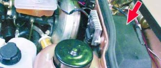
- provide access to the connector responsible for diagnostics;
- remove part of the console;
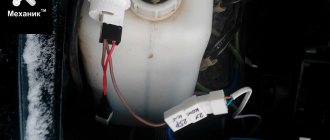
- connect a meter-long piece of wire (see image below);
Diagnostics using special equipment
1. Diagnostic connector
2. Connecting a wire with an adapter to the diagnostic socket
3. Connecting the wire to the computer
4. Running software for testing
The diagnostic process using special equipment consists of checking the car using a laptop. To connect to the diagnostic connector you will need a cable with an adapter. Using this cable, we connect the computer to the connector via USB output. For testing you will also need software; the power of the computer used is not important. There are many versions of different testing programs on the Internet.
Diagnostics is performed as follows:
- It is recommended to inspect the vehicle before starting the inspection. Check the volume of consumables - engine oil, brake fluid, coolant.
- Find the diagnostic connector and connect your laptop to it. If you have a special scanner, then that's even better. But since finding a scanner is not so easy, and buying one is not cheap, you can use a laptop. Before testing can begin, the ignition must be activated. There is no need to start the power unit.
- After connection, the testing utility starts. The software interface may vary. When you launch the software, graphs or a list of parameters with numbers may appear. This information will allow you to draw conclusions about the operation of the power unit.
- The scan starts. Fault codes will appear on the laptop screen. To decrypt, use the information provided in this article. We could not describe all the codes, but we deciphered those that occur most often. Usually, when downloading a program to a computer, users are provided with a separate file describing the faults.
- After decryption, the problem is repaired.
VAZ 2113-15 (AMK-211501)
Passport RUIB.402253.507-01 PS
Automotive route computer AMK-211501 (hereinafter referred to as the computer) is designed to process sensor signals and display vehicle movement parameters, fuel consumption, ambient temperature, on-board network voltage, timing parameters, diagnostics of electronic engine control systems (hereinafter referred to as ECM), as well as for detection obstacles and indication of the distance to them when the vehicle is moving in reverse (with a connected vehicle parking device).
We ask you to carefully read this passport, which will allow you to fully use the performance qualities of your computer. When purchasing, you must check the absence of external mechanical damage, completeness, presence and integrity of the factory seal, compliance of the serial number of the computer with the number specified in this passport, as well as the passport signed and stamped by the seller. The manufacturer may make minor design changes to the computer that do not impair its quality and reliability, which are not reflected in this passport. on-board computer for VAZ 2114 operating instructions Legal address of the manufacturer: Russia, 305038, Kursk, st. 2-ya Rabochaya, 23, JSC "Schetmash".
ATTENTION: THE COMPUTER IS SUPPLIED TO THE CONSUMER WITH A PROTECTIVE FILM ON THE GLASS OF THE COMPUTER PANEL, WHICH CAN BE REMOVED AT THE WISH OF THE CONSUMER.
ABOUT THE PRINCIPLES OF OPERATION OF SUCH SYSTEMS
Carburetor VAZ 2109 cars were equipped with devices with router functions. Installation of injection power plants VAZ 2114, VAZ 2115 and other models required the use of a completely different type of device. Most of its functional activities are devoted to diagnosing and controlling the operation of almost all devices and systems of vehicles.
The operation of the VAZ 2114 BC is based on and has the following operating principle:
- Receiving signals from sensors through the control unit, processing them and issuing messages on the display, as well as the ability to make adjustments for other systems;
- Processing signals from systems that are not controlled by the controller. In the event of an emergency, the corresponding icon is displayed on the information board, and a sound signal is also given.
Installing a computer on a car
The names of the signals and numbers of contacts of the computer plug are given in Table 1.
A description of the computer contacts is given in Table 2
| Fuel consumption signal input . A rectangular pulse signal with a frequency proportional to fuel consumption. The signal source is contact “2” of the DRT or contact “54” of the ECU (fuel injection controller) type M1.5.4 (January-5.1) or contact “32” of the ECU of type MP7.0. |
| Line "K" diagnostics . The contact is connected to contact “ M ” of the diagnostic block for VAZ vehicles or contact “ 11 ” of the diagnostic block for GAZ vehicles. Through this line, the computer exchanges information with the ECU. Data is transmitted in the form of a series of pulses with an amplitude from a low level (0 V) to the on-board network voltage. The line passes through contacts “ 9 ” and “ 18 ” of the control unit of the automobile anti-theft system (hereinafter referred to as APS), which must be closed in its absence or when the APS is not activated. The “K-line” signal from the car parking device is connected to this contact. |
| Voltage signal input from ignition switch . The signal from the ignition switch does not provide power to the computer; it informs the computer that the ignition is on. Used to measure on-board network voltage. |
| DVT signal input . The computer sends a +5 V voltage through this circuit through an internal resistor to the DVT, which is a thermistor with the second terminal connected to ground. The sensor changes resistance depending on temperature. |
| Non-switchable voltage input . Constant power supply to the computer from the vehicle's on-board network. The voltage comes through the fuse. |
| Voltage input of the car instrument scale illumination circuit . The signal controls the brightness of the computer indicator backlight. |
| Frame . The contact is connected to the car body (ground). The voltage at the contact should be close to zero. |
| Fuel level input signal . The contact is connected in parallel to the vehicle's FLS signal circuit. Connection location: car instrument cluster connector. The signal voltage value is used to calculate the fuel level depending on the type of instrument cluster and the installed fuel level table. |
| DSA signal input . A rectangular pulse signal with a frequency proportional to the speed of the vehicle. The signal comes from contact “2” of the vehicle’s DSA or from the output of the instrument cluster (speed signal for the computer) or from contact “9” of an ECU type M1.5.4, January-5.1, MP7.0. |
How to choose a quality bookmaker
The main rule when choosing a computer for a car is that the device must support collaboration with the computer. And secondly, you need to be guided by personal preferences. You must clearly understand for yourself what functionality the device should have.
The on-board computer from Multitronics fits perfectly into the VAZ 2114 car. Among the devices of this company, you can choose the best option for your car.
If BC is required to represent a limited number of parameters, economic models should be preferred.
Today there are a huge number of automotive gadgets for various purposes. The on-board computer can be universal - for monitoring car systems and accessing the Internet. It can also be highly specialized. Particularly popular today are route BCs, which allow you to build a route using an interactive LCD display, download various maps of the area from the Internet and perform a number of other useful actions.
The price range is quite wide - you can buy a device for 1000 rubles, or you can buy it for 5000 rubles. Of course, more expensive models have enormous capabilities. They can start the engine to warm up at a specific time, alert you to low tire pressure, and turn on the GPS navigation system.
If these functions are not critical for you, then you should choose an on-board computer from the budget segment and not overpay for functions that will never be useful.
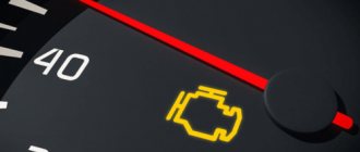
Basic error codes
A good BC not only displays the information the driver needs, but also deciphers error codes. If any of the vehicle systems fails, the corresponding error code will appear on the computer display. To decipher it and understand what the problem is, you need to refer to the documentation, which contains the entire necessary list.
To find out if there are any errors in the system, proceed as follows: reset your mileage for one day and get in touch.
Fault code 3 indicates a faulty fuel level sensor.
Code 6 indicates engine overheating, and error 7 can be interpreted as low oil pressure in the system.
The instructions for the VAZ 2114 on-board computer contain the entire list, so in case of an error, you must first refer to it.
Purpose of VAZ 2114 devices and interpretation of the symbols on them
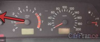
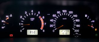
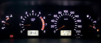
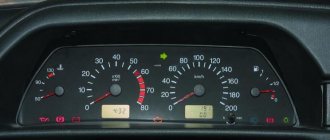
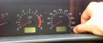
Located on the left side of the dashboard, directly in front of the driver's seat, the VAZ 2114 instrument cluster plays an important role in driving. It contains pointer instruments, VAZ 2114 indicators with electronic digital windows and signal lights for various purposes.
The numbers on the scale indicate:
The graphic symbol of a gas station at the top of the device indicates a fully filled tank. At the bottom right, an indicator in the form of a gas pump lights up in orange, indicating that the remainder in the tank is less than six liters.
Information functions
This list includes:
- current time and date;
- alarm timer;
- travel time from engine start to stop;
- total travel time (from reset);
- immediate fuel consumption;
- average fuel consumption per trip;
- total fuel consumption for the entire route;
- expected mileage on remaining fuel;
- current amount of fuel;
- mileage for the current trip;
- outside air temperature;
- instantaneous indicator of movement speed;
- voltage in the electrical network.
Watch
Type A and B
Time settings
The ignition key must be in the ACC (I) or ON (II) position.
To set the time
Press the H (hour) button to change the hour.
To set the minutes
Press the M (minutes) button to change the minutes.
Enter
| 1. Hours 2. Minutes 3. Reset |
Type B
| 1. Hours 2. Minutes 3. Reset 4. Time |
Press the RESET button to reset the minutes. The clock will be set to display the clock.
For example, if the RESET button was pressed between 9:00 and 9:29, the time will be reset to 9:00. If pressed in the time range from 9:30 to 9:59, the time will be set to 10:00.
9:01 — 9:29 = 9:00 9:30 — 9:59 = 10:00
When the device is turned off, the time is automatically reset to 1:00.
Type C
| 1. Install 2. Reset 3. Select |
Time settings
The ignition key must be in the ACC (I) or ON (II) position.
Press and hold the SET button for about 2 seconds until the clock indicator flashes. Release the button. Then press the SET button again to set the minutes and hours.
After setting the time, press the SELECT button to start the clock.
When the hour indicator on the watch is flashing, press the RESET button to reset the reading. The clock will be set to show the time in hours.
If the clock is reset when the display shows, for example, 9:01 to 9:29, the time is reset to 9:00. If a reset occurs between 9:30 and 9:59, the time will be reset to 10:00.
When the device is turned off, the time is automatically reset to 1:00.
Type D
| 1. Clock |
If the car is equipped with an audio system, the clock is built into the system itself.
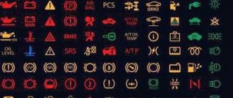
Designation of light bulbs and indicators on the instrument panel of the VAZ 2114
The dashboard, by definition, is designed to contain instruments, indicators and switches that could inform the driver about the current state of various vehicle systems, signal an emergency during the operation of the car or the failure of any units, as well as using buttons and switches control individual equipment or mechanisms.
The designation of icons on the instrument panel of the VAZ 2114 is made in accordance with all requirements and standards that call for the unification of symbols so that they are absolutely clear to every driver. The symbols on the instrument panel of a VAZ 2114 with the latest injection engine are located mainly in the lower part of the instrument cluster:
Indicators VAZ 2114
1 - the icon of the light indicating that the oil level in the engine crankcase has dropped below the minimum level, lights up in red;
2 - this light indicates an insufficient level of washer fluid; it lights up orange when the remainder in the tank is less than one liter;
3 - this icon, lighting up in orange, indicates a decrease in the coolant level in the expansion tank with a cold engine below the permissible level;
4 — warning light icon for unlocked doors, lights up red;
5 — fault indicator for “brake lights” or dimensions;
6 - this is a warning light for a malfunction in the brake system, indicating that the brake pads are worn out;
7 - light bulb icon that indicates unfastened seat belts.
On earlier versions of the car, the designation of the light bulbs on the dashboard of the VAZ 2114 in the lower part is slightly different, when viewed from left to right:
Designation of icons on the instrument panel of the VAZ 2114
In addition, car enthusiasts should know what the lights on the VAZ 2114 instrument panel mean, indicating the performance of the lighting equipment or the condition of the engine:
Instrument panel VAZ 2114: description of symbols
The instrument panel of the VAZ 2114 has a number of indicators and indicators that show the driver the status of on-board systems in real time.
There is an on-board computer here that reads instrument readings and displays information on the screen. This system greatly simplifies machine maintenance. If certain signs appear on the dashboard, troubleshooting occurs many times faster.
Each group has its own area of responsibility and can overlap with others, creating combinations that indicate complex breakdowns.