Faulty vehicle wiring leads to serious problems during the operation of the car - from incorrect operation of sensors and devices, on-board computer and automation to complete failure of expensive electrical equipment. Remember that a short circuit in the on-board circuits can lead to a fire in the vehicle. Therefore, faults in electrical equipment and electrical equipment should be eliminated immediately when they are detected - there is no need to put off repair work “on the back burner”.
You can repair car electrical wiring either yourself or at a car service center. The main difficulty lies in finding faults - breaks, failed relays, fuses and blocks, breakdowns of individual elements and auto electrical devices.
Common machine electrical faults
Auto electrics include various systems, parts, devices and elements of the vehicle - the ignition system, battery and generator, on-board computer circuits, fuses, sensors, relay blocks, various electronic sensors, auto lights, as well as auto electronics - climate system, audio system, automation and systems security. It is necessary to take into account the peculiarities of automotive electrical wiring in order to quickly find and eliminate a malfunction in the on-board network.
Common electrical problems include:
- Battery failure. This may be a consequence of insufficient electrolyte density, damage to the case with electrolyte leakage, destruction of the plates, or significant oxidation of the battery terminals.
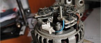
- Generator breakdowns - winding breaks, problems with the voltage relay, failure of the diode bridge, wear of brushes and bearings.
- Problems with the ignition system. We are talking about malfunctions of spark plugs, ignition coils, an open circuit or oxidation of the contact group.
- Deformations of electrical wiring - oxidation at connection points (inputs, contacts, terminals), breaks, destruction of wire insulation, short circuit of wiring, violation of the integrity of twists.
- Failure of electronic components. This refers to malfunctions of various electrical devices in circuits, devices and electrical equipment of a car (conductors, diodes, fuses, capacitors).
How to check wiring
You can diagnose electrical equipment using a voltmeter, ohmmeter or multimeter, or special diagnostic stands. Computer diagnostics are also carried out, during which error codes and main indicators of the machine’s on-board network are read. To independently check circuits and troubleshoot electrical faults, one multimeter or signal lamp is enough.
We use a multimeter
Fuses in the on-board network are considered the “weakest” link in terms of durability. In case of emergency situations (for example, in the event of a short circuit), the safety elements “take the blow”, protecting the rest of the electrics and electrical equipment of the machine. Fuses cannot be restored and must be replaced during repairs.
Checking the voltage
Before checking the wiring in the car, it is necessary to measure the voltage of the electrical circuit between individual components and electrical equipment. You can call like this:
- Set the multimeter to voltmeter mode.
- Connect one probe of the measuring device to the “minus” of the battery or to the ground of the machine.
- Connect the second probe to the supply wire of the circuit.
If a certain value appears on the device display, then there is voltage in this section of the electrical circuit. You can compare the values with those required according to the vehicle's owner's manual.
Looking for a short circuit
After measuring the voltage, search for short circuits. This will require either a multimeter or a pilot light. As for the lamp, if the wiring is in good condition and there is no short circuit, it should not light up.
A short circuit in the wiring, as well as a lack of voltage (zero or infinite resistance in the electrical circuit), indicates a malfunction in one of 2 components:
- Consumer - electrical equipment, devices, fuses, blocks.
- Wiring – broken or shorted wires, poor wiring contacts at the point of connection with the consumer.
Checking for a short circuit can also be done in voltmeter mode. To do this, it is necessary to remove all fuses in the area being tested and connect the probe to the terminals of the fuse element. The value “0” on the screen indicates the presence of a short circuit in the circuit. If, when you try to move the wires, voltage appears in the circuit, then the short circuit is caused by the wiring and the wires will need to be replaced.
Checking the quality of grounding
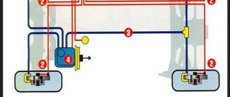
Cars use a single-wire wiring diagram - this means that the “minus” goes to the ground (body) of the car. However, corrosion of metal parts, their oxidation and destruction, “loosening” lead to grounding failure and, as a consequence, to disruption of on-board circuit contacts.
Checking the grounding, as well as other electrical elements of the car, is carried out using a multimeter. The procedure is as follows:
- Disconnecting the battery.
- Connecting one multimeter probe to the body (metal parts) of the car.
- Connecting the second probe to the grounding element or wiring connection.
Read also: How to disassemble the motor of a screwdriver
The value displayed on the device screen should be compared with the factory data (car operating manual). If the values diverge greatly, then it is necessary to restore the grounding - clean the metal at the connection point, check the reliability of the fastening.
Checking the integrity of the circuit
The connection of wires in the electrical circuit of cars is one of the most vulnerable points in the entire electrical system of the car. In addition to the destruction of insulation, loss of integrity and breaks at the connection points, oxidation of the contacts also often occurs here. Defects can be determined not only using a measuring device, but also visually. If the integrity of the circuit is broken precisely at the connection point, then soldering of wires with connectors will be required. Otherwise, you need to find the damaged area, which will require a signal lamp or multimeter.
Continuity of wires
Before starting any measuring work, it is imperative to check the serviceability of the tester itself.
It happens that the measuring system itself is faulty. To check, the ends of the probes of the measuring device are in contact. If the device is operational, the indicator will display zero or deviate slightly. A slight deviation indicates that the probes and terminals have their own small resistance.
If the multimeter has a sound signal, then the device is set to buzzer mode. This is done by placing the switch on the corresponding icon on the tester body.
The probes are brought to the ends of the part being tested.
Possible tester behavior options:
- A zoom will sound if the wiring is not damaged.
- The cable may be fine, but it is very long. In this case, the resistance of the conductor will be much greater than that at which the sound signal is triggered. The display will come to the rescue and display the resistance value.
- If the indicator shows one, then the resistance value is higher than the permissible range of the multimeter scale. You need to switch to another range and repeat the measurement.
- If the conductor is faulty, the multimeter will not perform any action.
When taking measurements with a multimeter, do not allow the human body to come into contact with probes and wires where there is no insulation.
Car electrical wiring repair
You can check and restore the car's electrical wiring yourself or at a car service center. After identifying faulty areas where there is damage to the wires, a short circuit or a break, they are soldered or completely replaced. Conventional twisting followed by crimping is not a full-fledged repair, but only a temporary measure - take this into account if you do not have the opportunity to solder the break points.
Wires are selected with the same characteristics as the existing damaged ones (resistance, metal). You should not install too long wires with a “reserve”; twisted open wiring under the influence of negative factors (temperature changes, moisture, dirt) is destroyed faster - this can lead to a short circuit. When replacing wiring harnesses with connectors, make sure that the contact groups are completely free of oxidation before work.
Mounting blocks located in the engine compartment are also considered a vulnerable element of a car's electrical system. Due to the destructive effects of temperature and moisture changes, damage to the protective coating and subsequent defects in tracks, connectors for connecting wiring harnesses, relays, and capacitors are possible. Repair of mounting blocks, consisting of circuit boards, fuses and electrical components, includes soldering to restore tracks and coating with a special protective varnish, as well as replacement of faulty elements and wiring, connectors, cleaning contact groups from dirt and oxidation.
Features of automotive wiring
Indeed, all these wiring harnesses that encircle the car from top to bottom perform the only task - to ensure the uninterrupted transmission of electrical impulses between the components of a particular system. And if one of the wires has poor contact, or even worse, the terminal is burnt out or oxidized, then the operation of the circuit will be disrupted or even fail.
Replacement is simple; it’s more difficult to find the location of a break or short circuit with your own hands, especially if you don’t know how to do it.
In this article we will try to answer many questions, including:
- how to test the wiring in a car to find a fault;
- how to properly repair the actuator;
- how to restore bad contact;
- how to solve other electrical problems.
Troubleshooting wiring requires basic knowledge and precise tools.
What's under the hood
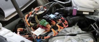
In the engine compartment there are many wires that perform a wide variety of functions:
- transmitting high voltage pulses from a current source (generator or battery) to the engine cylinders;
- transmitting data from various sensors;
- ensuring continuous operation of the fuel supply system, lighting fixtures, etc.
The wiring of the ignition system deserves the greatest control.
What's in the cabin
Inside the car, intended for the driver and his passengers, there are even more wires, since there are:
- Automotive system controls:
- control of external lighting devices (road lighting, maneuvering signals and rear brake lights);
- management of audio devices;
- automatic transmission control;
- control of electronic assistants (cruise control, automatic windshield wipers, navigation system);
- Control devices and sensors;
- Active safety systems:
- electric seat belts;
- driver and front passenger airbag mechanisms;
- Comfort features:
- air conditioner;
- window regulators;
- musical equipment;
- heating systems for windows, mirrors, seats, etc.
Replacing the wiring in a car will necessarily require disassembling the instrument panel.
Note! Wiring harnesses run through the interior to the rear of the car. Therefore, there is a maximum concentration of electrical wiring inside the machine.
Replacing car wiring
When replacing wiring in a car, be sure to turn off the power, including disconnecting the battery. Of course, this is not a precaution against electric shock, but protection of the vehicle’s electrical equipment from possible short circuits that may occur during repair work.
Sometimes the replacement can be completed in 10-15 minutes - for example, if the wires of the “battery-generator” supply circuit are damaged. If the integrity of the wiring in the cabin is damaged, there are problems with grounding, or a short circuit in the on-board computer circuit, then the work will take much more time. And the main thing here is not to make a mistake, since incorrectly connecting the wires (for example, if the polarity is reversed) can cause a short circuit, damage to expensive electrical equipment and even a fire. If you do not have experience in electrical engineering and electrical installation work, it is better to contact a specialized service for the services of a professional auto electrician.
Many car enthusiasts, when problems arise with electrical wiring, immediately begin frantically looking for a familiar auto electrician to solve the problem, citing the fact that they do not understand electricity. In fact, there is nothing difficult about carrying out electrical diagnostics yourself. To do this, you will need a multimeter and a little knowledge, which we will try to outline for you in this article. Read the information below and you will not have any questions about how to find a short circuit in a car or, conversely, how to find a broken wire in a car.
Signs of faulty wiring
Before diagnosing the car's electrical system, you need to make sure that the problem is with the wiring. We list the main types of electrical wiring faults and their symptoms:
- Short circuit. One of the most dangerous problems with wiring, which can cause hazardous smoke and even fire - these are actually signs of a short circuit in the car. It is important to immediately stop using the car, since overheated wires from a short circuit can melt the insulation of adjacent wires and only worsen the situation. Most often, such problems end with a blown fuse or relay.
- Broken wiring. This is a safer malfunction, the consequences (and, at the same time, signs) of which can only be the failure of a certain electrical unit (in some cases, the entire electrical system).
Short circuit in the car
To answer the question of how to find a short circuit in a car, first check all the fuses and relays - as a rule, if there is a short circuit, one of them should fail. After finding such a fuse or relay, find out from the description (on the cover of the fuse box) which unit it belongs to. Next, start examining this unit - visually inspect all the wires running from it to the fuse box.
Read also: Casting gold at home
If external signs of a short circuit are not found in the car, then set the multimeter to resistance measurement mode, and then disconnect the “plus” of the unit being tested from the fuse box and from the device powered by it. Then connect one contact of the multimeter to the positive wire, the second contact to ground. If there is no short circuit, then the resistance on the multimeter will be equal to one. Otherwise, the “plus” somewhere touches the “minus”.
How to detect a short circuit
Step-by-step instructions on how to determine a short circuit with a multimeter:
- When electrical devices and the network are turned off, you need to measure the circuit resistance in individual nodes. If possible, it is advisable to use a wiring diagram for the electrical supply of a house or apartment. If a lot of resistance is shown, then this section is working. And in places with a short circuit, the resistance will be 0. However, the device can also display a high resistance indicator, mainly if there is a large distance to the short circuit. For this option, it is advisable to use a megohmmeter;
How to ring electrical wiring
This process is mainly done using a multimeter. This device is quite inexpensive, so it is advisable to have it in your tool kit.
The easiest option for dialing is to perform it at the installation stage. How to do it correctly:
- check the wire for the appropriateness of the declared power. The cross-section of the wire will be equal to the total power of the electrical appliances that will be used in this network;
- check the cable insulation for integrity. This can be done visually;
- measure the insulation resistance with a megohmmeter. For an electrical circuit with a standard voltage of 220 V, the resistance should not exceed 0.5–1 MOhm;
- correctly check the network under maximum load. To do this, you need to turn on all the devices at once.
Checking circuit continuity
You can also test the wiring using a socket. Move the range knob to the AC voltage measurement position. It is necessary to set the indicator to 750 V. The probes of the device are connected to the holes in the socket. The voltage should show 220 V. The maximum error is 10%. If it exceeds the permissible deviation, then it is necessary to use surge protectors to connect household appliances.
How to check circuit continuity
To test the integrity of electrical wiring, you must use a digital multimeter operating in resistance mode. When carrying out the test, you need to make a closed circuit, which consists of the device itself, two measuring “probes” and the wire being tested.
Attention! During operation, a small electric current is passed through the test area, and the device will recognize the indicator of its internal resistance. This option is suitable for those who do not have special electrical skills.
How to ring wires in a car
- Use the handle to set the device to voltage measurement mode;
- Connect the end of the device to the ground of the car or to the minus of the battery. A distinctive feature of the power supply pair in the machine will be that the negative wire is either very short or completely absent;
- The second probe touches the supply wire. It must be disconnected from the device clamp.
Finding broken wiring in a car
In order to check a car for current leakage with a multimeter, you will need to perform the same steps. Measuring resistance is an indicator of the presence or absence of contact. In the absence of contact, the resistance tends to infinity (or the number “1” on the device). If there is contact, the resistance should ideally tend to zero (the lower the better). So, to check for a break in the wiring, you need to connect a multimeter to two contacts suspected of a break and measure the resistance; we repeat - a unit on the multimeter screen will indicate a break.
Thanks for subscribing!
To avoid a repeat break, do not twist the wires with your hands. Use only a soldering iron and special heat shrink. If there is a break in the terminal, be sure to clean it before repairing.
How to check a car battery with a multimeter
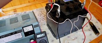
If you suspect that the battery is not working well, then again, a multimeter will help you. So, arm yourself with a multimeter configured to measure voltage (20V):
- Disconnect one terminal and connect the red contact to the positive and the black to the negative. Normal voltage should be between 12.4 - 12.8 Volts. It is important to take measurements at least an hour after stopping the engine.
- Measure the voltage under a load equal to twice the capacitance. For example, if the capacity is 75 Am/hour, then the load should be 150 Am. If the voltage drops below 9 Volts, it means something is wrong with your car’s battery (undercharging or failure). After disconnecting the load, the voltage should be restored within 5-10 seconds.
To repair home electrical wiring or a car's on-board network, you always need to know how to test wires with a multimeter. This device tests the integrity and serviceability of the cable; it can be used to check the insulation resistance and current voltage in the home electrical network. This is an indispensable meter for wiring and practical implementation of electrical projects.
Optional equipment
During operation, car owners often install additional electrical equipment:
- Alarm;
- More powerful lighting fixtures;
- Audio and video equipment, etc.
Integrating them adds wiring to the vehicle and also puts stress on the electrical system. Moreover, a number of “new” electricity consumers cannot be switched off, for example, alarm systems, which means that the likelihood of rapid battery discharge becomes very important.
Current leakage is also determined using a multimeter
If your car begins to have difficulty starting after a long period of parking, then you should determine the cause of the current leak. A multifunctional device switched to ammeter mode will also help you find a leak.
Tip: Don’t forget to set the measurement range to 10 Amps, since the current in the car’s on-board network is constant.
Setting up and preparing the multimeter
To use the multimeter correctly, you need to configure it. This means that you need to select the value to be measured and the limit of its operation, that is, the value beyond which it will not go.
Symbols on the front panel of the meter
A multimeter can be used to check various electrical quantities: current, voltage, resistance, frequency. It is also used to test the performance of various radio elements: resistors, capacitors, diodes and transistors. The very part of the word “multiple” implies the presence of several types of measurements. To select these types, there is a knob on the front panel of the tester, by turning which you can select the required value.
There is a higher class type of multimeter, for example, Agilent, in which the selection of measurement values is made not with a rotary knob, but with buttons. To select a value, simply click on the button corresponding to this value.
In most cases, the symbols depicted on the body of the multimeter represent designations of electrical quantities accepted in physics or conventional graphic designations of radioelements intended for testing . On the front panel you can find the following symbols:
- U - voltage symbol;
- V - stands for volts, this is also a measure of voltage;
- I is the current; when you set the knob to this designation, the current strength will be measured;
- A - amperes, a measure of current strength;
- Ω, R - symbol of resistance;
- Ohm is a measure of resistance, Ohms;
- -| |- - this icon indicates a capacitor, the multimeter will measure its capacitance;
- Diodes and transistors are also marked on the tester body with their symbols.
But not only the measured values are indicated on the front panel of the tester: the holes for connecting the probes also have their own designations. One of the meter slots will always be occupied by the black probe. This is a common hole, it is usually marked with the inscription COM, which means “common”. In addition to it, the multimeter has two or three working holes, designed respectively for measuring voltage, low current and high current.
The socket marked U, Ω, Hz is intended for measuring resistance, voltage and frequency, as well as for testing various radio elements. You also need to install a probe here to test wires and cables for breaks.
The hole marked mA (mA) is used to test low currents (up to 1 ampere), and the hole marked A (10 A) is needed to measure high amperages.
Also next to the voltage and current icons there are symbols
or -. This indicates the nature of the measured quantity: direct or alternating current or voltage.
Limits of measured values
In addition to designations of the values of the parameters being tested, designations of measurement limits are printed on the front panel of the multimeter. In more advanced equipment, these inscriptions are not present, since the tester electronics itself selects the limit based on the signal supplied to it at the input. However, most multimeters require manual adjustment of measurement limits.
Read also: Alexander Shenrock speed control with power maintenance
Typically, limits are given by numbers that are multiples of 2: 2, 20, 200... Thus, when choosing a limit, you should be guided by the rule: choose a limit higher than the one being measured, but of the same order. For example, to measure the voltage in a home electrical network (in an outlet), you need to select the AC voltage measurement mode and the measurement limit of 2000 volts. And to test the wires with a multimeter, you need to select the resistance mode and the minimum measurement limit of 2 ohms. However, long cables require a higher measurement limit of 20 ohms. Additionally, you can turn on the button with a sound signal that sounds when a short circuit occurs (circuit presence).
Connecting the tester
To check the parameters of electrical circuits and the continuity of wires and cables with a multimeter, you must correctly connect the meter to the circuit being tested. When checking for circuit integrity, the required area between the meter leads is checked. Therefore, the tester is connected to the terminals of the circuit. If voltage is being measured, the multimeter must be connected in parallel to the section where the voltage is being tested.
When measuring current, the multimeter must be connected in series to the open circuit of the circuit being tested, for example, between the power supply terminal and the load terminal.
Operating principle
The analog type of the device does not require its own power supply . Its operating principle is the same as that of an ammeter, and an analog device works best in the range of radio waves and electromagnetic fields. There are induction coils inside the device body, and when the probes touch the conductor, a current begins to form in the coils. The created magnetic field deflects the indicator needle to a certain angle. The magnitude of this angle depends on the strength of the current generated, and the arrow on the drawn scale indicates the measurement value.
Digital devices contain a textolite printed circuit board on which a digital chip , which is responsible for processing the received data. To operate the electrical circuit and screen, digital devices are powered by batteries or an external power source.
Digital multimeters have lower measurement uncertainty and are more accurate than their analog counterparts.
There is a switch on the front panel of the multimeter that selects the measurement mode. The switch sets the scale factor that determines the value on the device scale.
Analog instruments have two types of scale:
- Uniform display.
- Logarithmic exponents.
The uniform scale is very sensitive to overloads, so the switch is first set to a large scale factor value, which is gradually reduced. The logarithmic scale does not have this drawback and has a range of values from zero to infinity.
Thus, the main components of multimeters are:
- Display for showing measured values.
- Connectors for probes and probes themselves.
- Switch for different modes and ranges.
Checking electrical circuit parameters
When testing electrical circuits, you can test many of their parameters. This includes current, network voltage, and signal frequency. But to determine serviceability, you only need to ring the circuit for integrity and check the insulation resistance. Both can be done with a multimeter.
In order to know how to test electrical wiring with a multimeter, you need to correctly configure the measuring device and correctly perform the measurement steps. To check the integrity of the wire you need:
- Connect the black probe of the multimeter to the socket labeled COM, and the red one to the socket labeled U, Ω, Hz;
- The meter knob must be set to the 20 Ohm position;
- Connect the measuring contacts to both ends of the wire. If the ends are in different places in the room, you need to use a previously tested extension wire;
- The tester screen will display the value. If the value does not exceed 2 ohms, it means that the integrity of the wire is not compromised. If the readings are not at the same level or more than 8-10 ohms, then there is a break in the circuit.
In the same way, wires in a car and cables of various electronic devices are tested.
In addition to checking integrity, wires are tested for insulation resistance. This can also be done with a multimeter:
- The probes remain in the same holes as when checking integrity;
- The measurement mode selected is the same - resistance test;
- The measurement limit must be selected as large as 20 or 200 megaohms;
- Touch the probes to opposite conductors of the cable: phase and neutral or phase and screen. In a car, this is ground and signal wire;
- The screen should remain displaying infinity; if there is any value instead, it means there is a short circuit somewhere. Changing values indicate interference in the network.
In addition to ordinary wires, there are high-voltage wires that can withstand high current and voltage loads. These include spark plug wires in cars. The current that is required when starting the engine flows through them; this current reaches 80-150 amperes. Knowing how to test high-voltage wires with a multimeter is required when diagnosing car electronics. The ringing of these wires occurs according to the indicated diagram , with the difference that it is necessary to set a larger resistance measurement limit. Typically this limit should be set at 20 kilo-ohms.
After this, you need to find the ends of the wire and connect the multimeter probes to them. The resistance of this wire will be displayed on the device screen. It should be in the range from 1 to 10 kOhm.
In trucks, as well as in networks located in places subject to constant mechanical stress, conductors with a screen - armor or armored wires - are placed. The only special feature of the armored wire is the screen, made of durable metal. You can check the integrity and insulation of the armored wire in the same way as a regular one, you only need to have access to its ends and the screen outlet.
Device structure
Devices may differ in appearance, but multimeters are fundamentally divided into analog devices and digital devices.
Analogue devices are already gradually being replaced from the market by digital ones, but in the homes of many home craftsmen you can still find analog devices.
Such devices are equipped with an indicator screen with a scale and arrow. The advantage of these models is the clarity of display of measurements. The deflection of the needle is visually easier to assess than the flashing of numbers on the electronic display of digital instruments. Often, when making a call, it is necessary to evaluate approximate resistance indicators or, in general, its presence or presence, so analog devices are suitable for most practical work.
Digital multimeters have more complex electronics and a digital display. This type of device is used mainly in production and industry.
The housings of all multimeters have outputs for two probes. These are two insulated wires ending in needle-like metal tips. In some cases, special clips, so-called “crocodiles,” are put on the nozzles. When choosing a device, you need to pay special attention to the quality of the probes. The correctness of measurements depends on them.
The wires must be flexible with strong soldering and fit well into the device sockets. It often happens that outwardly spectacular probes are of unsatisfactory quality and have poor technical characteristics.
Safety requirements
When performing any inspections of live electrical networks, safety requirements must be followed. You cannot work without protective insulated shoes, and it is also better to wear rubber gloves. When checking the integrity and insulation resistance of electrical circuits, it is necessary to de-energize the network by turning off the circuit breakers, so all checks should be carried out during daylight hours, since with emergency lighting and the light of lanterns you can only work in case of an emergency.
What is a multimeter
A multimeter device is used mainly for measuring voltage, current and resistance in an electrical circuit and in its individual sections. Simply put, the device in one shell has a voltmeter, ammeter and ohmmeter.
What does the device look like?
Depending on the device and the number of additional options, it is used to study the integrity of an electrical circuit, monitor and measure the characteristics of its components.
The device can also measure direct and alternating current.
When measuring each characteristic (current, voltage, resistance, etc.), you first need to:
- visually determine the measurement scale. So, for a battery it will be 1.5V, 7.5V, 12V and higher. The value must be taken more than necessary. Simply put, this is a “strength reserve” so as not to break the device;
Multimeter design
- choose the correct measuring direction. In this case, it is necessary to move the device pointer to the required position, based on the generally accepted parameters indicated on the body;
- connect the probes correctly. For any type of measurement, the negative (black) probe is inserted into the common socket (COM), the positive one is connected into the socket required for a specific type of measurement.