Recommendations for increasing the service life of the regulator
In order to increase the service life of the voltage regulator, it is necessary to adhere to several simple rules aimed at implementing preventive measures.
Among them:
- do not allow excessive contamination of the generator, periodically inspect its condition, and, if necessary, dismantle and clean the unit;
- check the tension of the alternator belt, tighten it if necessary (either yourself or in a car service);
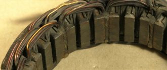
- monitor the condition of the generator windings, in particular, do not allow them to darken;
- check the contact on the control wire of the relay-regulator, both its quality and the presence of oxidation on it;
- Perform periodic voltage checks on the vehicle battery with the engine running.
Following these simple rules will allow you to increase the resource and service life of both the generator and the vehicle voltage regulator.
conclusions
In the electrical system of a car, the voltage regulator relay of the Bosch generator (as, indeed, of any other company) plays a very important role. Monitor its condition as often as possible and check for damage and defects. Cases of failure of such a device are not uncommon. In this case, in the best case, the battery will be discharged. And in the worst case, the supply voltage in the on-board network may increase. This will lead to the failure of most electricity consumers. In addition, the generator itself may fail. And its repair will cost a tidy sum, and considering that the battery will fail very quickly, the costs will be astronomical. It is also worth noting that the Bosch generator voltage regulator relay is one of the leaders in sales. It has high reliability and durability, and its characteristics are as stable as possible.
Checking the removed voltage regulator
To make sure that it is the LV that has failed, and not the generator itself, it should be checked separately. To do this, you will need to disconnect it from the main device.
The procedure is as follows:
- Remove the negative terminal from the battery.
- We find the place where the launch vehicle is attached to the generator. Unscrew the 2 screws that secure it.
- Disconnect the yellow wire going from the regulator to the generator.
- We dismantle the launch vehicle.
- To diagnose the device, you will need a power supply with the ability to adjust the output voltage, a light bulb (12 V) with a socket and a pair of wires.
The verification algorithm is as follows:
- We assemble a “control” from a lamp and wires and connect it to the regulator brushes.
- Set the voltage on the power supply to 12 V.
- We connect the “plus” from the power supply to the “D+” terminal of the regulator, and the “minus” to its “ground”.
- We look at the lamp: it should be lit.
- We increase the voltage on the power supply to 15-16 V. If the regulator is working properly, the lamp should go out. If this does not happen, the LV must be replaced.
The process of replacing the voltage regulator is not particularly difficult. All you need to do is purchase a new device, check it as described above and install it on the generator, fastening it with two screws. And don't forget to connect the yellow wire!
Reasons for replacement
Relay replacement is needed in the following cases:
- The brushes are worn out. By the way, this is the main reason. The fact is that due to their wear, contact with the relay is lost, so due to lack of power, the generator will stop working.
- A breakdown is observed in the circuit, which leads to an increase in voltage in the system.
- Wire breaks causing loose contacts.
- Damage to the housing or fastenings. This is not something to joke about, as it can lead to an unwanted short circuit.
Relay replacement
Note: It is usually black and is attached to the generator with a yellow wire.
- Disconnect the negative terminal of the battery.
- Unscrew the two bolts securing the generator.
- Remove the yellow wire going to the relay from the generator.
- Remove the relay. Examine it carefully. If the brushes are worn out, replacement cannot be avoided.
- If any of the wires are broken or there are holes on its surface, then you can only get by by replacing them.
Note: you can simply insulate them without even replacing them with new ones. Although the relay is inexpensive - only 70 rubles.
- Check the new voltage regulator, and then attach it to the generator.
- Reconnect the yellow wire and battery terminal.
As noted earlier, you can replace the relay with your own hands. The main thing is to familiarize yourself with the work process in advance so that questions do not arise later. To do this, you can find photos in various auto repair magazines. It’s much easier to use videos, of which there are many on the Internet. Our instructions will also help in this difficult matter. But the price of home repairs will not exceed 100 rubles.
Voltage regulator - its main functions
On a VAZ 2110 car, the voltage potential in the generator is formed under the influence of alternating current. This phenomenon becomes possible due to the presence of silicon diodes in the generating device of the vehicle.
The generator rotor (the rotating component of the mechanism) operates according to the following diagram:
- First, the crankshaft begins to function, which is affected by the current;
- the crankshaft sets the movement of the rotor;
- After this, the generating device itself begins to work.
All stages of the sounded process are monitored by a voltage regulator, which is also often called a relay. It is this that is considered the main control unit of the generator.
Without a regulator, the current-generating mechanism of the VAZ 2110 will not perform its tasks, which are listed below:
- starting the generator;
- control (in offline mode) of current supply;
- “holding” in a certain voltage range.
The described relay cannot be repaired. In the event of a breakdown, the regulator must be replaced, which is done after checking the functionality of this unit.
Connection diagram and operating principle
The voltage regulator on most cars is connected to the on-board network according to the diagram below.
The operating principle of a voltage regulator (VR) is the same as that of a relay. In other words, it opens and closes an electrical circuit. That is why the device is also called a relay regulator. It is triggered when a predetermined voltage value coming from the generator changes.
The first regulators had an electromagnetic design. These were real relays. Modern devices are made on the basis of semiconductors. They are small in size, and in addition, they work much more accurately and efficiently. Some of them are even equipped with special alarms that allow the driver to monitor their performance.
How to check the relay on a VAZ 2110?
To analyze the condition of the regulator, you need to purchase a voltmeter, which has a measuring scale in the range of 15–30 volts.
The check is performed as follows:
- start the car engine at medium speed and let it run for a quarter of an hour (the operation is carried out with the headlights on);
- A voltmeter is used to determine the voltage between the “ground” of the generating device and the “plus” on the battery.
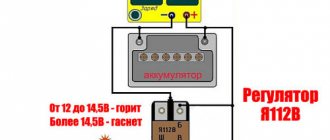
If the measurement shows a voltage value from 13.5 to 14.2 volts, replacing the regulator is not necessary. But in situations where the voltage has a different value, indicating a constant overcharging or undercharging of the battery, the relay needs to be replaced.
You can also remove the voltage regulator and check it together with the generator brush holder. To do this, a 12-volt light bulb with a power of 1–3 watts is placed between the brushes, a power source is connected to the “ground” and the positive terminal of the battery, from which a voltage of 12 volts is first supplied, and then 16 volts.
If the light comes on at 12 volts and goes out at 16, replacing the regulator on a VAZ 2110 is not necessary. If the lamp does not light up, this indicates that there is no required power contact between the relay terminals and the brushes, or that a break has occurred. And the burning of the lamp at 12 and 16 volts indicates a breakdown of the regulator.
Device check
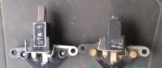
The relay-regulator of the voltage of the VAZ 2106 generator, “kopecks”, and foreign cars is checked equally. As soon as you remove it, look at the brushes - they should be more than 5 millimeters long. If this parameter is different, the device must be replaced. To carry out diagnostics, you will need a constant voltage source. It would be desirable to be able to change the output characteristic. You can use a battery and a couple of AA batteries as a power source. You also need a lamp, it must run on 12 Volts. You can use a voltmeter instead. Connect the plus from the power supply to the voltage regulator connector.
Accordingly, connect the negative contact to the common plate of the device. Connect a light bulb or voltmeter to the brushes. In this state, voltage should be present between the brushes if 12-13 Volts are supplied to the input. But if you supply more than 15 Volts to the input, there should be no voltage between the brushes. This is a sign that the device is working properly. And it doesn’t matter at all whether the voltage regulator relay of the VAZ 2107 generator or another car is diagnosed. If the control lamp lights up at any voltage value or does not light up at all, it means that there is a malfunction of the unit.
How to replace the generator voltage relay?
If you have some skills, removing and disassembling the mechanism described in the article does not cause difficulties for a person. The most difficult thing is to change it for the first time, and subsequent replacements, as a rule, take place quickly and without problems.
The regulator on a VAZ 2110 is dismantled according to the following scheme:
- disconnect the negative terminal from the battery;
- disconnect the drive block from the terminal marked “D+”;
- unscrew the nut, which is located under the rubber boot (it needs to be moved a little to the side);
- disconnect all existing wires in the contact pin;
- unscrew the nut in the generating device circuit (this fastener secures the terminal) and remove it.
Then you will need to remove the generator casing by unscrewing the nuts (there are three of them) that hold it in place, as well as dismantle the relay housing and remove the screw securing the disassembled mechanism from the rectifier compartment. Now the VAZ 2110 voltage regulator can be easily removed. You can install a new device instead. After replacing the relay, all the described steps are performed in the reverse order.
Checking the generator components on the table with a multimeter
Once a malfunction is suspected, the device is dismantled and diagnosed.
- Place the car on a viewing hole or lift the front part with a jack, and place a safety support.
- Loosen the fastening, disconnect the negative terminal from the battery.
- Disconnect the wires from the generator.
- Unscrew the adjusting and mounting bolts.
- Remove the belt.
- Remove the device and disassemble.
- Checking the diode bridge of the VAZ 2110 generator with a multimeter is performed in resistance measurement mode, range 0 - 2 MOhm. Silicon diodes used in the rectifier circuit, passing a current of up to 80A during operation, heat up. The cooling radiator is a metal mounting ring. Structurally, two types of rectifiers are produced: with an anode and a cathode on the body. Motorists call parts of the first type positive, the second - negative. A working diode in the forward direction shows a resistance of 0 Ohm, in the reverse direction - about 600 kOhm. A zero value in both directions means a breakdown of the device, a high value means a break. Additional diodes are checked in the same way.
- The rotor field windings are tested with a tester at the switch position of 0 - 5 Ohm. Test leads are connected to slip rings. The resistance value ranges from 1.8 – 5 Ohms. Less is a short circuit, more is a gap.
- The stator windings are tested in the range 0 - 200 Ohm. Alternately touching the terminals of two serviceable windings will show units of Ohms on the instrument indicator; the absence of readings means a malfunction.
- The integrity of the winding insulation is measured by touching one probe to the winding contact, the other to the housing. An infinitely large value indicates normality.
The final confidence in the serviceability of the generator will be given by testing on a bench.
Source
Three-level generator voltage regulator for the “ten”
When the heating system, headlights and other additional loads are turned on on the VAZ 2110, the car battery discharges very quickly. This phenomenon is observed even when the “native” generator relay is functioning normally. A three-level regulator allows you to get rid of this problem. You can purchase it at any auto store, equip yourself with a simple set of tools (terminal pliers, a knife, an S10 open-end wrench and a Phillips screwdriver) and install it on the car yourself.
The three-level mechanism is mounted as follows:
- first remove the old relay according to the algorithm given above;
- grind the ends of the spacer bushing using a file (this operation ensures more reliable contact with the diode bridge);
- a new element with a brush holder (sold as a set) is installed in place of the relay;
- Sealant is used to seal the cable entry point;
- put back the plastic casing;
- lay the cable along the standard wiring to the area where the relay is mounted, and secure the new wire tightly with small plastic clamps.
It is recommended to connect the housing of the installed voltage relay and the autogenerator using a reliable shunt. This ensures the necessary contact of the device with ground. However, you can do without a shunt.
The mounted three-level mechanism should be checked with a tester at full consumer load (window heating, stove, headlights, etc. are turned on). At maximum, the device should show 14.5 V, in normal mode - 14.1 V, at minimum - about 13.4 V.
Modern voltage regulation systems
If the voltage regulator relay for the generator of a Chinese scooter is two-level, then more advanced devices are used on expensive cars. Multilevel control systems can contain 3, 4, 5 or more additional resistances. There are also tracking automatic control systems. In some designs, you can refuse to use additional resistances.
Instead, the frequency of operation of the electronic key increases. It is simply impossible to use circuits with electromagnetic relays in servo control systems. One of the latest developments is a multi-level control system that uses frequency modulation. In such designs, additional resistances are required, which are used to control logic elements.
Voltage regulator VAZ 2110 - diagnostics and repair
After installing the HBO, a problem arose with electricity consumption in the on-board network. That is, with the low beams, fogs, and radio on, the voltage dropped to 12.7v.
In principle, I often saw on the drive that people install RNT for themselves, and I have long wanted to buy one for myself, but I always forgot about it. In general, I started reading installation and compatibility manuals. I took 94xx.3701 for the series of generators, since I have exactly that series!
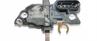
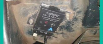
The regulator itself is in the box
67.3702-02 VOLTAGE REGULATOR (three-level) 12 V. (VAZ, GAZ from gen. series 94хх.3701)
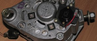
In fact, replacing the generator brushes without removing the generator itself turned out to be a piece of cake.
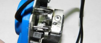
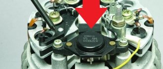
To remove the back cover of the generator, simply unscrew the nut holding the terminals, disconnect the thinnest wire and press out the 3 clips on the cover itself (marked in red)
Unscrew the 2 bolts holding the old brushes and disconnect the wiring. Install brushes from 3-level
I didn’t solder anything, I just bit through one side, unscrewed the contacts from the relay itself, and stuck it through the generator cover. Then I screwed the contacts back to the relay, in principle, you don’t even need to remember which contact connector you need to connect to on the relay, the black contact has a smaller hole than the red one, hence the bolts are of different diameters
Cottered
I attached the relay itself to the adsorber mount, since I don’t have one.
Well, the result is with the car running in Normal mode. I didn’t set other modes, I was afraid of the maximum mode, as they say that the battery might boil.
Idling.
Low beam.
Low beam + fog lights.
Low beam + fog lights + rear fog lights
Low beam + fogs + rear fogs + heated rear window.
In general, something like this, to say that I’m not happy is to lie!
Theory of the issue
Three-level voltage regulator for VAZ 2114
While the car is moving, a dead battery receives a charge voltage of 13.6 to 14.2 V. For the correct and stable operation of all systems in the car, these voltages must be maintained until the engine starts and the crankshaft rotates. Together with the motor, torque is supplied to the generator through the drive belt. At this moment, an amount of energy is generated that will be sufficient for the stable functioning of all systems and to maintain a charge on the battery.
If the generator does not charge, then in most cases the reasons must be sought in the excitation circuits, as well as in the output voltage circuits from the generator to the battery. But this is not always the case. Sometimes problems are related to the generator itself.
When the driver turns the key in the lock, the relay in the ignition system also starts at the same time. “Plus” flows through the relay and fuse in the mounting block. Next, the voltage passes through the on-board network, reaching the battery charge lamp and charge sensors. It then passes through diodes, relays, elements in the mounting block and finally to the connector in the generator. There, electricity comes to the relay-regulator and, passing through brushes and slip rings, enters the exciting winding.
Three-level voltage regulator for VAZ-2110
Domestic cars have a serious problem of rapid battery discharge. Unstable battery operation leads to rapid loss of resource, and buying a high-quality battery today is not a cheap pleasure.
The main provocateur for the rapid failure of batteries is the frequent change of operating modes and little depends on the driver of the vehicle. The battery, in turn, requires different voltages to charge.
To solve this problem, a regulator comes to the rescue. The standard device installed by default does not cope well with its responsibilities, because the circuit uses a very simple design that supplies only constant voltage. The disadvantage of such a regulator is that it does not take into account the speed of the vehicle, the amount of energy required and the ambient temperature.
A three-level voltage regulator can optimize all these processes.
Regulator relay - purpose, operating principle, types.
The reason for the appearance of a relay regulator in a car's electrical circuit was the fact that the generator does not always supply the battery with the voltage necessary for proper charging. The main problem is the variable speed of the crankshaft and, accordingly, the shaft of the electric generator, the latter generating an unstable voltage. The functioning of on-board network devices and battery charging require stabilization of the generator output signal.
The regulator relay performs the following functions:
- Voltage stabilization at the generator output in a given range;
- Cut-off (disconnection of charge circuits) when the maximum permissible level is exceeded.
The excitation winding of the generator is connected through the device. In fact, the PP performs the functions of a negative feedback circuit - an increase in the speed leads to an increase in the voltage at the output of the generator (battery terminals), thanks to the PP, it decreases on the excitation winding, a decrease in the excitation magnetic flux, and a decrease in the output voltage of the electric generator. When the speed decreases, the reverse process occurs. In this way, the battery receives up to 14.2-14.5 V (in some car models up to 14.8 V) regardless of the shaft rotation speed.
If the specified value is exceeded at the battery contacts, the supply of voltage to the terminals is completely blocked.
Types of relay regulator.
RRs are classified according to several criteria.
Based on the element base used, devices are divided into:
- Relay, using only switching relay contacts for stabilization and cutoff;
- Transistor and hybrid transistor-relay, built on the basis of semiconductor elements (used in cars produced before the 90s);
- Integrated, the architecture of which is based on integrated semiconductor and solid-state switching components, operating in modern cars;
- Microprocessor (microcontroller) with software specification of operating algorithms (modes) (widely used in high-end cars, for example Audi, BMW).
External (separate devices mounted on body structures);
- Built-in, structurally included in the generator;
- Combined with the brush assembly of the electric generator.
There are also devices with adjustment by “+” and “-” (connected to the break of the corresponding wire), two-, three- and multi-level.
What is the advantage of three-phase regulators
The main advantage of such devices is the ability to preserve the life of the car battery. This is very important for any driver.
The list of benefits does not end there:
- Eliminates heating problems.
- In cold weather the engine will start faster.
- Problems with alarms disappear, which quite often happens to vehicle owners. Such surprises especially happen in winter.
- The power of light emission from lamps increases. Visibility will improve both with low and high beams.
- The regulator can also affect the operation of the vehicle's heating system. There is an established opinion among experienced drivers that the stove works much better with a fully charged battery.
- Some car enthusiasts have noted that power windows work faster with a working battery.
As you can see, a high-quality battery with an additional three-level regulator can save you from a lot of problems.
Symptoms of a problem
So, in case of low voltage, the battery simply will not charge. That is, in the morning you will not be able to start the car, the lights on the dashboard may not even light up, or troubles will arise while driving. For example, dim headlights at night, unstable operation of the electrical system (problems with electrical appliances - wipers, heaters, radio, etc.).
In case of increased voltage, there is a high probability of a decrease in the electrolyte level in the battery banks, or its boiling. A white coating may also appear on the battery case. When overcharging, the battery may behave inappropriately.
Signs, malfunctions, repair of generator and voltage regulator
In addition, you can also identify the following signs of a faulty voltage regulator (in some cases, some of them may or may not be present, it all depends on the specific situation):
- the control light on the dashboard (although this may be a sign of other malfunctions, for example, that it has burned out, the contact has fallen out, and so on);
- after starting, the battery indicator on the dashboard does not go out, that is, there are obvious malfunctions in charging the battery;
- the brightness of the headlights becomes dependent on the engine speed (you can check this somewhere in a deserted place by placing the car against a wall and accelerating - if the glow changes, then most likely the voltage regulator is faulty);
- the car stopped starting normally the first time;
- constantly discharged quickly ;
- when the engine speed exceeds 2000 rpm, the indicators on the dashboard turn off ;
- the dynamic characteristics of the car decrease , this is especially noticeable at high engine speeds;
- In some cases, the battery may boil .
Regulator connection process
Before starting installation work, disconnect the negative terminals from the battery. It is important to completely unscrew it from the battery.
Next, unscrew the generator nut using the appropriate wrench. To gain access to the casing, the block is removed, which is usually secured with three latches. To disconnect, you need to slightly pry the block from the edge. Next, the casing should be easy to remove.
The next step is to unscrew the screws, but first make sure that the plug is completely removed. Next, the nut is removed, the ends of which should be well processed with a file. This is necessary in order to improve the contact of the diode bridge with the bushing. The brush holder is mounted in place of the regulator. It is important to take care of its seal during installation in order to fix the device more securely.
The next step is to reinstall the plastic casing in its place and you can begin laying the regulator wire. Do everything carefully and take into account the placement of the main wiring of the machine.
To prevent the wires from dangling, secure them with plastic clamps.
Only after all the above steps are completed, the device itself is installed. Contact with ground must be reliable. Often, a shunt is used for this, which makes it possible to fasten the regulator and generator housings much better.
Once the device has been connected, you need to screw in the other wires from the kit. Upon completion of all installation work, the functionality of the device should be checked. It is important to load the battery to full - turn on the stove, radio, headlights, and so on.
What does the second set of fuse boxes do?
The symbols F1-F20 indicated below in the electrical diagram are the elements that characterize the set of fuses. The electrical circuit in a VAZ-2110 car is protected using fuses based on the specific calculation of the model for the rated current value specified upon purchase.
At the same time, fuses are not responsible for the quality operation of the circuit consisting of a sample battery, a separate type of generator circuit, the ignition system and engine valve starting. To replace a faulty fuse in this mounting block, follow the following plan:
- Find a fuse that has mechanical damage or its body has burned out;
- According to the instructions, determine and eliminate the reason why it turned out to be faulty;
- Install a new fuse using the backup model.
Tip: Never try to replace a fuse with special jumpers. In the future, this will lead to failure of those devices that are assigned to this fuse.
Diagram with designations for the second set of fuses in the block
All fuses are divided according to their interaction with electrical equipment as follows:
- F1 (current 5A) - fuse responsible for the set of lamps that illuminate the license plate, the entire instrument panel, including the side lights and lighting in the trunk.
- F2 (current 7.5A) - element that regulates the low beam on the left headlight.
- F3, F4 (current 10A) - responsible for the operation of high beam in the left headlight and right fog lamp, respectively.
- F5 (with a current of 30A) - is responsible for the electric window motor at the front and rear car doors.
- F6 (with a current of 15A) - refers to the operation of a portable lamp.
- F7 (with a current of 20A) - regulates the operation of the fan motor in the cooling system of a 16-valve engine, as well as the operation of the sound signal.
- F8 (with a current of 20A) - supplies current to the heating elements located on the rear window. In addition, together with the contacts from the relay, it transmits current to the windshield.
- F9 (with a current of 20A) - is responsible for the operation of the recirculation valve. It also interacts with the windshield wiper and washer sensors and headlights.
- F10 (with a current of 20A) - is a backup fuse.
- F11 (with a current of 5A) - regulates the operation of lamps with side lights on the starboard side.
- F12 and F13 (with a current of 10A) - both fuses regulate the operation of the right headlight, responsible for the low/high beam, respectively.
- F14 (current 10A) - adjusts the light from the left fog lamp.
- F15 (with a current of 20A) - interacts with the electric heating of the driver and passenger seats. Protects the car from unauthorized blocking of the central locking in the trunk.
- F16 (with a current of 10A) - transmits current to the breaker relay to ensure the operation of the direction indicator of the left and right headlights, and is also used to give an emergency signal (when using the emergency signal mode on the VAZ-2110).
- F17 (current 7.5A) - works with the car interior lighting lamp, brake light lighting, individual lighting of the ignition system switches and regulates the operation of the trip computer.
- F18 (with a current of 25A) - illuminates the glove compartment, supplies current to the heating system controllers and the cigarette lighter on the dashboard.
- F19 (with a current of 10A) - is responsible for the operation of the door locks, and also informs the driver about the presence of a malfunction in the brake light lamps or side light elements.
- F20 (current 7.5A) - works with the lamps of the rear pair of fog lights of the VAZ-2110.
Having dealt with the fuses, you can also learn about how to bleed the brakes on a VAZ-2110. Often the operation of the braking system greatly affects the operation of the car in general and electrical equipment in particular.
Is it worth making the regulator yourself?
If you are new to electronics, then such an undertaking will be quite difficult.
As we mentioned earlier, the main element of the circuit is a certain number of diodes. Finding three-stage switches for them is quite problematic. In addition, you need to correctly calculate and install radiators for cooling. Otherwise, the risk of diode burnout increases significantly.
During the development of the regulator, long wires will be needed, because the connection is made directly to the device through the cover.
Additionally, you will need to make or find a suitable plastic case for such equipment. All internals must be securely fastened inside the device.
Carrying out diagnostics of RN with your own hands
Now we’ll tell you how to check a three-level voltage regulator with your own hands. The procedure for checking the regulator can be carried out both at a service station and in a garage, but we will consider the second option. Testing a voltage regulator of 40 amps or less should be done using a tester - a voltmeter or a multimeter. It should also be taken into account that fault detection in the operation of the launch vehicle should be carried out exclusively with a fully charged battery.
So, how to check the generator voltage regulator using a tester:
- First of all, you need to open the hood and turn the key in the lock, turning on the ignition.
- Next, the power unit is started. The engine should idle for some time; to obtain more accurate diagnostic data, it is recommended to turn on the optics. The engine speed when running should be around 2.5-3 thousand. For the internal combustion engine to switch to this operating mode, you usually need to wait about 10 minutes.
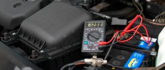
- Then the tester probes are connected to the battery terminals. When you connect the tester, diagnostic indicators should appear on its display, ideally they should be approximately 14.1-14.3 volts.
If the check shows other values, be they higher or lower, then you need to start repairing the generator unit. But as practice shows, the problem usually lies precisely in the launch vehicle, so most likely it will have to be replaced. Before starting diagnostics, make sure that the belt is properly tensioned. During diagnostics, contacts must not be closed, as this may cause deformation and failure of the rectifier unit.
Relay and fuse blocks VAZ 2112: description and explanation
Modifications of mounting blocks and fuses of the VAZ 2112 have changed more than once during the production of the model. Radical innovations were introduced only in 2002 after the appearance of a 16-valve injector.
In 2006, there was only one unit in the cabin, and in 2007 a console unit was added to it. This happened thanks to changes in the shield and gearbox, and the addition of a Europanel. The cover of the main unit became hinged, which simplified access to the fusible elements. Separate inserts outside the mounting blocks, for example, under the brake pad, have been preserved.
Repairing a generator - VAZ features
To check the car's power supply, you need to take measurements at the battery terminals. To do this, you need to start the car and let it run for a few minutes. After this, take readings with a terminal tester. Next, turn on all possible car devices, dimensions, tape recorder, heating and repeat the measurements. With a properly functioning voltage generator, as well as its regulator, the average voltage in the network should be 12–13 Volts.
The most normal voltage in a VAZ 2109 car is 14.1 Volts. If your readings are more or less than the acceptable average, then you need to start repairing your generator. First of all, you need to check the ground on the generator block. It often happens that it oxidizes under the influence of moisture. Because of this, it may not carry enough current to the vehicle. This terminal is located on the generator block; it needs to be cleaned and lubricated.
Another reason for a lack of vehicle current is a sufficiently worn or loose alternator belt. Using a belt, the generator is driven by the operation of the car engine. If the belt is not tensioned enough, it will slip while driving. Thus, the car generator will not perform the required number of revolutions, and accordingly, the required amount of current will not flow.
If the generator does not produce enough voltage, the battery is not fully charged, which significantly affects its service life. To fix the problem you need to replace the belt or tighten it
It is very important not to overtighten it, as during movement it will stretch much faster or may even burst. You should not buy belts of dubious production - a low-quality belt wears out very quickly, dries out and stretches.
Additional block
It is located under the center console and is covered with a lid. One part is accessible from the right side.
Designation
p, blockquote 27,0,0,0,0 —>
- 15A - Ignition module, controller
- 15A - Canister purge valve, vehicle speed sensor, oxygen concentration sensor (heating), air flow sensor
- 15A - fuel pump, fuel pump fuse, injectors
- Electric fan relay
- Fuel pump relay
- Main relay (ignition relay)
The other part is on the left side of the console:
Decoding
p, blockquote 31,0,0,0,0 —>
- Central locking control unit
- Immobilizer block
- Relay for turning on rear fog lights.
On our channel we also prepared a video on this publication. Watch and subscribe.