How to replace a voltage regulator
Before replacing the voltage regulator, be sure to check the generator as a whole (How to check a generator?). The voltage regulator needs to be changed if the voltage under load of the on-board network (high beam, heated mirrors, heater are on) is less than 13V. Also, the voltage regulator can cause high voltage (above 14.7V). But, as stated above, before removing the regulator, you need to check the generator itself, become familiar with other possible faults (for example, the generator belt is loose), and only then proceed to replacing the voltage regulator. You will also need this article to replace the generator brushes, because... brushes and voltage regulator are installed on the generator assembly.
OTHER REASONS FOR NO CHARGING
If the battery is not charged or is insufficiently charged, in addition to a faulty voltage regulator, there may be other reasons related to the generator:
- The belt is poorly tensioned;
- Poor contact or break in the wires supplying power;
- Faulty rotor or stator winding;
- Poor contact of the brushes with the rotor commutator, the brushes are simply worn out.
New and worn alternator brushes
How to remove the voltage regulator?
- Open the hood, remove the negative terminal of the battery, find the generator, disconnect the wire block “D”.
- Remove the protective rubber cap from the tips of the “+” terminal wires. We unscrew the nut securing these wires and remove them from the generator block.
- Next, we need to remove the plastic generator block itself (most often it is black). To do this, you need to disconnect the three spring clips located around the perimeter of the block.
- We find the voltage regulator, and use a Phillips screwdriver to unscrew its fastenings.
Next we need to check the voltage regulator to make sure it is faulty. To do this, read the article “How to check the voltage regulator?”
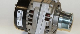
Generator
The generator is designed to generate electricity, which is so necessary for the stable operation of the vehicle's electrical equipment. Additionally, it performs the function of recharging the battery - with a discharged battery it will be impossible to start the engine. For the VAZ 2114 model, the nominal voltage of the electrical circuit is considered to be 12 Volts, but taking into account all consumers (lighting, ignition system, instruments, stove motor, windshield wiper motor, etc.) it should always be higher. Therefore, the voltage in the electrical circuit can range from 13.2 to 14.7 Volts. To maintain it at the required value, a regulator is installed in the generator circuit. Moreover, this device is present in any car, and not just on the 2114 model.
Replacing the voltage regulator on a VAZ 2114
A voltage regulator is a device that changes the electrical voltage at the output of an electric motor when it receives a control signal. The VAZ 2114 voltage regulator is built into the electric generator and provides stabilization of the output voltage by changing the excitation current in the generator.
Generator brushes VAZ 2114
Replacing the battery charging relay VAZ 2114 2110
Hello, visitors to our site! I want to tell you a story that happened two weeks ago. Arriving from work one day, I, as usual, opened the hood to see if everything was in order and discovered that the peephole on the battery was white.
Of course, this “eye” shows the condition of only one battery bank, but still I decided to check the voltage with a multimeter. I have a new battery, a little over a month old, and this peephole “tells” me that the battery needs charging. Taking a regular multimeter, I measured the voltage at the battery terminals with the engine turned off. The voltage was 12.3V. Then I started the engine and measured 13.7 at idle without load, and with the low beams, heater and radio on, only 12.8, and this is not enough to charge the battery, and the battery charging light did not light up (it lights up when you turn the key in the first position). After thinking a little, I decided to check the condition of the generator brushes.
Operating principle of the voltage regulator (VR)
RN is structurally an electromagnetic relay and a series-connected transistor circuit with resistances, which themselves are connected in series to the excitation winding on the generator stator. The physical meaning of the activity of an electronic launch vehicle is as follows.
The generator voltage is unstable and changes abruptly. As it increases, the electric relay turns on additional resistance, which limits the excitation current and the voltage decreases. If, on the contrary, the voltage drops below the permissible value, the relay turns off the resistance and the magnetic flux in the field winding increases, and the generator voltage increases. Since this is all a high-frequency process, the voltage in the automotive electrical network remains within an acceptable stable value.
If we consider the launch vehicle in a practical sense, then this device solves the following problems:
- this device activates the electric generator;
- it exercises autonomous control over the output of alternating current;
- maintains a constant set voltage value, regardless of the amplitude of oscillations generated by the primary windings of the generator.
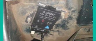
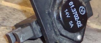
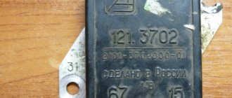
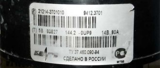
For the generator model 9402.3701, which is mounted on a VAZ 2114, a voltage regulator 611.3702-14 is installed. This electrical appliance is mounted complete with a brush assembly. Technical characteristics of the launch vehicle:
- rated voltage supported by the regulator is 14.5 V;
- rated current - 5 A;
- maximum weight - 60 g;
- size - 66x55x32.
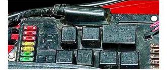
Fuse and relay diagram for VAZ 2114, 2115, 2113
The power supply circuit of the injection system is protected by a fuse-link made of wire with a conductor of reduced cross-section (1 mm2). The battery charging circuit, the engine starting circuit, and the “generator - ignition switch - mounting block” circuit are not protected by fuses.
Mounting block 2114/2115-3722010 / -3722020:
-3722010-08, -3722010-10, -3722010-18
Mounting block 2114/2115-3722010 / -3722020:
-3722010-30, -3722010-38, -3722010-40, -3722010-48, -3722010-60, -3722010-68,
| № | A | Purpose |
| 1 | 10 | Rear Fog Lamps, Rear Fog Light Indicator, Headlight Cleaner Motor, Headlight Cleaner Relay (Contacts), Headlight Washer Actuator Valve |
| 20 | Central locking, rear fog lamps, rear fog lamp indicator | |
| 2 | 10 | Hazard and turn signal relay (in hazard mode), hazard warning indicator |
| 3 | 7.5* | Brake lamps, front interior lamp, central interior lamp, luggage compartment lamp, ignition switch illumination lamp, Check Engine indicator, trip computer |
| 10* | Brake light lamps, interior lamp, individual interior lamp, luggage compartment lamp, lamp integrity monitoring relay, trip computer, ignition switch illumination lamp, Check Engine indicator | |
| 4 | 20 | Cigarette lighter* , heated rear window, heated rear window relay (contacts), socket for portable lamp |
| 5 | 20 | Cooling fan, horn, horn relay |
| 6 | 30 | Window lifters, power window relay (contacts) |
| 7 | 30* | Cigarette lighter , heater motor, rear wiper, windshield washer, headlight wiper motors (in operating mode), glove compartment lamp, rear window heating relay (winding), cooling fan relay, rear window washer timing relay, windshield washer activation valve and rear windows, rear window heating relay (winding), rear window heating indicator |
| 20* | Cigarette lighter, heater motor, windshield washer, headlight wiper motors (in operating mode), glove compartment lamp, rear window heating relay (coil), cooling fan relay, windshield washer valve, rear window heated relay (coil) ), rear window heating indicator | |
| 8 | 7.5 | Right fog lamp |
| 9 | 7.5 | Left fog lamp |
| 10 | 7.5 | Side light lamps on the left side, side light indicator, license plate lamps, engine compartment lamp, instrument lighting switch, backlight lamps: (switches, instruments, cigarette lighter, ashtray, heater control levers) |
| 11 | 7.5 | Side light lamps on the starboard side, lamp integrity monitoring relay* |
| 12 | 7.5 | Right headlight (low beam) |
| 13 | 7.5 | Left headlight (low beam) |
| 14 | 7.5 | Left headlight (high beam), high beam indicator |
| 15 | 7.5 | Right headlight (high beam) |
| 16 | 15* | Hazard and turn signal relays (in turn signal mode), reverse lamps, instrument cluster, generator field winding (in engine start mode), lamp health monitoring relay, on-board control system display unit, low oil pressure indicator, parking indicator brakes, brake fluid level indicator, low battery indicator, trip computer |
| 20* | Hazard and turn signal relay (in turn signal mode), reverse lamps, generator field winding (in engine start mode), low oil pressure indicator, parking brake indicator, brake fluid level indicator, low battery indicator, voltmeter, carburetor choke indicator (choke), low fuel level indicator, windshield wiper, coolant temperature and fuel level indicators. | |
| 17 | — | Spare |
| 18 | — | Spare |
| 19 | — | Spare |
| 20 | — | Spare |
| Relay | ||
| K1 | -10, -18, -40, -48: Headlight cleaners (90.3747-01 - 21100-3747210-31 (-38, -48), 2105-3747210-02, 2107-3747210-02) | |
| Jumper | ||
| K2 | Hazard alarm and direction indicators (495.3747 - 21080-3747010-02 (-08)) | |
| K3 | Windshield wiper breaker (526.3747 - 21140-3747710 (-00, -08)) | |
| K4 | -00, -08, -10, 18, -30, -38, 40, 48: Lamp integrity monitoring (4412.3747 - 21100-3747410 (-00, -01, -08), 21150-3747410-00 (-01, -08)) | |
| -60, -68: Jumper | ||
| K5 | -10, 18, -30, -38, -68: Window lifters (90.3747-11 - 21100-3747210-31, 21050-3747210-12 (-18, -38), 2107-3747210-12) | |
| K6 | Sound signal (90.3747-11 - 21100-3747210-31, 21050-3747210-12 (-18, -38), 2107-3747210-12) | |
| K7 | Heated rear window (90.3747-11 - 21050-3747210-12 (-18, -38), 2107-3747210-12) | |
| K8 | High beam headlights (90.3747-11 - 21050-3747210-12 (-18, -38), 2107-3747210-12) | |
| K9 | Low beam headlights (90.3747-11 - 21050-3747210-12 (-18, -38), 2107-3747210-12) |
*Depending on mounting block
Additional fuse and relay box (fuel injection system)
This unit is located at the bottom left under the glove compartment on the center console
| № | A | Purpose |
| 1 | 15 | Fuel pump, fuel pump relay (contacts), injectors |
| 2 | 15 | Constant power supply to the controller, electric fan relay (winding), canister purge valve, air flow sensor, speed sensor, oxygen sensor (heating) |
| 3 | 15 | Main relay (engine control unit, ignition module) |
| Relay | ||
| K1 | Fuel pump | |
| K2 | Cooling fan | |
| K3 | Main relay (engine control unit) |
- Mounting block - located in the engine compartment
- Relay (2105-3747210-20 (-21, -22, -24, -28, -58))
- Ignition relay () - installed on the left (small relay), next to the rear fog light relay.
- Rear fog light relay (2114-3747610 (-01, -02, -03)) - installed on the left (large relay), next to the ignition relay.
- Front fog light relay (2105-3747210-58) - installed in the engine compartment next to the battery
Additional fuses
- Rear fog light (8A) - located in the wiring harness
- Heated seats (16A) - located in the wiring harness
- Central lock (16A) - located in the wiring harness
How does a voltage regulator work?
In terms of its design, the three-level voltage regulator VAZ 2114 is a relay with a transistor circuit and resistances connected to it, which, in turn, are connected to the exciting winding on the generator stator.
The principle of its operation is as follows - during its operation, the generator produces current with an unstable, intermittent voltage, the use of which directly in the on-board network could lead to malfunctions and even breakdowns of electronic equipment. In order to eliminate these surges and maintain the voltage produced by the generator at the same level, a stabilizer regulator is needed.
So, when generating too high a voltage, the device includes additional resistors in the circuit, which lower the voltage to the desired level. Otherwise (when the voltage is too low), the stabilizer turns off all resistance in the circuit, and the voltage produced by the generator increases.
Speaking about the operation of the stabilizer, one should also take into account the fact that all these adjustment voltage fluctuations occur at a high frequency, as a result of which the total voltage in the on-board network remains virtually unchanged.
In simple terms, the voltage regulator of the VAZ 2114 generator is responsible for:
- activation of the electric generator;
- control of the current supplied by the generator;
- maintaining the voltage supplied to the on-board network at a stable level.
For the regulator mounted on the 14th model, the standard operating parameters are a nominal voltage of 14.5 volts and a nominal current of 5 amperes.
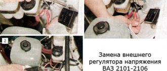
Replacing the battery charging relay
1. Disconnect the negative cable from the battery.
2. Turn off the minus generator
3. Unscrew the nut securing the “plus” of the generator and remove the plastic cover by bending the latches
4. Unscrew the two screws securing the voltage regulator (the generator has been removed for clarity) and remove it
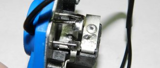
The brushes must protrude from the voltage regulator by at least 5mm. My brushes protruded 1-1.2 cm.
Almost new, one might say. The brushes did not jam and were generally in good condition. Next, I cleaned the terminals of the battery itself and the “+” contacts or, as it is also called, the “B” output of the generator. I measured the voltage again - the picture was the same. The charge is bad. After weighing all the pros and cons, I decided not to disassemble the generator (if you decide to disassemble the generator, go here), but to replace the voltage regulator (despite the good condition of the brushes). This element in the generator is perhaps the cheapest. I bought it for 230 rubles. Having replaced the regulator and started the engine, I hastened to check the voltage. The long-awaited reading of 14.1V appeared on the multimeter. Having turned on the low beam, stove, speakers and heated glass, the device showed. 13.6V. The battery began to charge again. Next, I removed the battery and charged it at home. Now, two weeks later, all battery readings are normal. I hope this article will be useful to someone.
Similar articles
How to replace a voltage regulator
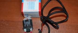
If during the test it turns out that the regulator is faulty, then you should replace it with a new one of a similar model as quickly as possible.
This should be done as follows:
- Disconnect both terminals from the battery.
- Disconnect the block with wires connected to terminal “D” of the generator.
- Remove the rubber cap from the “positive” terminal, using a 13mm wrench, unscrew the nut securing the bundle of wires to the stud.
- Remove the wires from the pin contact.
- Open the 3 plastic clips on the lid.
- Using a flathead screwdriver or narrow blade, remove the cover.
- Using a Phillips screwdriver, unscrew the 2 screws securing the regulator.
- Disconnect the wires leading to the device.
- Remove the regulator housing along with the graphite brushes.
Installing a new voltage regulator should be done in the same order, but in reverse order.
When installing a new regulator, be sure to clean all its contact surfaces and check the tightness of the contacts. Otherwise, failures and incorrect operation of the device may occur.
Finishing the conversation about the voltage regulator, I would like to remind you once again that at the first sign of a malfunction of the device, you should replace it with a new one, since otherwise there is not only a risk of failure of the on-board electronics or increased fuel consumption, but also the likelihood of a short circuit with further fire cars.
Signs of regulator malfunction
Sometimes during the operation of a car it happens that the stabilizer fails. Signs of this may include frequent fluctuations and sudden surges in voltage in the vehicle network, problems with electrical appliances and rapid discharge of the battery. If you notice one or more of the above signs, then the relay regulator of the VAZ 2114 generator should be tested using a multimeter.
Checking the voltage regulator VAZ 2114
You can do this as follows:
- Set the tester to measure DC voltage with a limit of 20 volts.
- Measure the voltage readings at the battery terminals with the engine turned off (the result should be from 12.5 to 13 volts).
- Start the engine and measure the voltage at the terminals again (now it should be between 14 and 14.5 volts).
- Without turning off the engine, turn on the high beam, heater and heated glass (other powerful consumers can also be used). Measure the voltage on the battery a third time. The voltage readings should be in the range of 13.2-13.9 volts - this will mean that the stabilizer is fixed. Otherwise, the device will have to be dismantled and replaced.
Traveling in a car with a faulty generator regulator is not profitable and even unsafe, as this can lead to increased fuel consumption, breakdowns in the on-board network, and even a car fire.
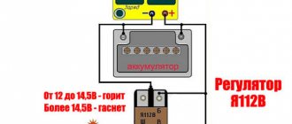
You can check the correct operation of the regulator without using a multimeter, with the device removed. To do this, you need to connect its “ground” terminal to the negative of the battery, and connect contacts B and C to the positive. After this, you should take a 3-watt car lamp and connect it to the graphite brushes of the regulator. If the latter is working properly, the lamp will light up.
New and damaged voltage regulator
In some cases, you can go even further and check the trigger threshold. To do this, the regulator should be connected as mentioned above, but between its positive terminals and the plus of the battery, connect a pair of AA batteries in parallel in order to increase the voltage in the network to 16 volts. If the regulator is working correctly, it will interrupt the power supply and the light bulb connected to its brushes will not light up.
Generator failure - how to determine?
A breakdown of the generator entails big troubles - electrical appliances may fail and the battery life will be reduced. So, if the voltage regulator relay fails, the generator may produce a voltage greater than required. This can cause problems in the correct readings of electrical appliances, as well as in the operation of the car's lighting.
To independently check the functionality of the generator, you will need a tester and an assistant. First of all, insert the key into the ignition and start the car. The battery light on the dashboard should illuminate to indicate a low charge or an open circuit. It is necessary to warm up the car to operating temperature and turn on all possible devices in it.
Then take a tester and check the voltage at the battery terminals. During this time, your partner should keep their foot on the gas pedal and maintain 3000–3500 rpm of the engine. The voltage on the tester in a VAZ 2114 car with a normal working generator should be at least 12–13 Volts. If the voltage is less, it is necessary to proceed with a detailed check of the device. Urgent repairs are also required if the current is greater than 14.7 Volts. This applies not only to the VAZ 2114, but also to other passenger cars.
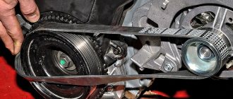
When checking the operation of the generator, you need to listen to its sound. The presence of a characteristic hum or noise from belt friction indicates wear of its bearing, in which case a complete repair of the device is necessary. Also, quite often the ground contact on the car’s generator turns out to be poor, because the wire is located quite low in the VAZ 2114. During rainy weather, water gets on it, which causes oxidation of the contact terminal.
Another reason for low voltage may be a tight or sufficiently worn alternator belt. As a result, the generator may not turn the required number of revolutions to maintain normal power supply. In this case, it is necessary to tighten it or replace it. The work of tightening or replacing the alternator belt will not take much of your time, and also does not require specific technical skills.