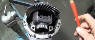
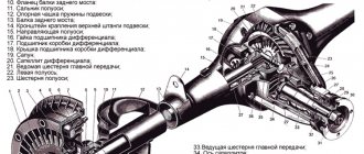
The VAZ 2106 rear axle gearbox is the main device that transmits the generated power from the engine to the wheels. This design is used on almost all domestic Soviet-style cars. It has proven itself to be a fairly strong part, but breakdowns still occur.
Timely and high-quality maintenance will help to extend the service life as much as possible.
Despite the fact that there are a large number of cars on which the gearbox is installed, in most cases its structure is the same. Its main task is to transfer force from one device to another. At the same time, the speed of its movement can change the intensity and direction. This is the main purpose of the device in the rear axle system.
Gearbox device
Design of the VAZ 2106 rear axle gearbox
In order to understand the design of the gearbox, you need to simultaneously consider other parts included in the unit.
The design of such a unit must be considered together with other elements included in its composition.
The main constituent elements are two parts:
- Main gear;
- Wheel differential.
In addition, it includes:
- Direction pin;
- Drum;
- Bearings and their fastenings;
- Oil seals;
- Breather;
- Satellite;
- Flange and much more.
When the engine is running, a certain force is created. Due to the operation of the gearbox, it moves between the gears. It is the combination of these gears that is called the main gear, which transforms the torque and directs it to the wheels. Due to the cross-axle differential, the load is distributed between the wheels and allows them to rotate at the required frequency when the direction of movement changes. This is exactly how the gearbox works on a VAZ 2106 car. Due to the simplicity of the design, its use is ensured without problems in any conditions.
Device types
The VAZ gearbox can be of various types depending on the components. The main gears have an unusual shape, and the teeth are at a variety of angles. This is explained by the fact that a hypoid type transmission is used. Its main advantage is low noise level, jerk-free operation and reduced load on each tooth. Thus, the entire mechanism can be operated for a long time and, as experience shows, quite reliably. The same gearbox is installed on many other models of domestic cars.
Types of rear axle gearboxes VAZ 2106
In addition, the main transfer can be performed in other ways. For this purpose, transmissions are installed:
- Conical;
- Cylindrical;
- Worm-shaped.
However, in most cases, it is the first type that is used, since its efficiency is maximum and its cost is relatively low.
It is also necessary to note the cross-axle differential, which is used to supply torque to the wheels in varying degrees. In other words, this is a planetary gearbox included in the bridge design. A different device is installed on SUVs and crossovers, since their tasks are slightly different.
How to repair the rear axle gearbox on a VAZ 2101-VAZ 2107?
Note!
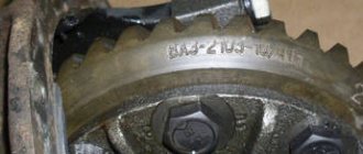
The gearboxes that went into classic cars were all practically the same, they only had a difference in the gears and therefore each gearbox is marked with the numbers 2106, 2103, 2102 and 2101, the repair of all gearboxes is also identical and does not require too high skills for this, the most important thing is to have a torque wrench and think with your head during the repair process and then you will succeed 100%!
Disassembly:
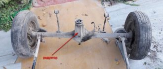
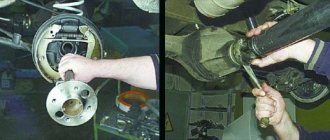
- Before you start disassembling the gearbox, you need to remove it from the car; if you do not know how to perform this operation, we recommend that you read it in the article that is posted on our website and it is called: “Replacing the rear axle gearbox on a VAZ.”
- Now, with a cloth, clean the entire gearbox from dirt and then put it where it will be most convenient for you to work (a workbench, for example, or you can lay it out on the ground, but just don’t lose anything in this case), then take a wrench in your hand and use it to turn it out the bolt that secures the locking plate (see photo 1), immediately after the bolt is unscrewed and the plate is released, remove it from the gearbox (see photo 2), perform exactly the same operation on the other side of the gearbox, respectively, with the other plate, when both locking plates will be removed, use a center punch, and use it to put marks on the bearing caps as shown in the figure number 3, the whole point is that the caps will need to be installed during assembly in exactly the same places where they stood previously and therefore (the cover of everything two, left and right) on each cover you need to make a mark relative to the body to which it is bolted, after the marks are made, select the cover that you will remove first (It doesn’t matter, but they need to be removed separately, it will be easier) and start unscrewing the bolts that secure it (Only two bolts secure one cover, see photo 4).
Removing the locking plate and marking the bearing caps to understand which cap goes where
Note!
Let us clarify once again about the marks that you need to make (This is for those who have not yet understood), we definitely recommend that in addition to the marks, you also put numbers or several marks on the lid, now we will explain everything! Since the covers must be installed strictly in the same way and strictly in their places, you can, for example, mark the first cover with one mark and this will mean that this is the right cover; on the second cover you can put two marks and this will indicate that it is left cover, for more details about where the marks need to be applied, see the photo below:
The arrows show marks made with a center punch and when reassembling the gearbox, you won’t get confused about which cover to put where.
- Then, when the bearing cover mounting bolts are unscrewed, take them out and remove the cover itself, as well as remove the adjusting nut as shown in photo 3 and then install the outer bearing ring after it and remove it too (see photo 4).
Removing the bearing cap bolts, removing the cap and removing the adjusting nut and bearing outer race
Note!
Perform exactly the same operation on the other side of the gearbox, but only when you remove the outer ring of the bearing on that side, mark it with something (a felt-tip pen, for example) and you will no longer confuse which outer ring is installed where, just their location also matters (If When the bearing is replaced, it will also have new rings, so if you have already bought a repair kit and there is a bearing and this ring, then there is no need to mark the removed one with anything)!
- Now that nothing is in the way, we move on to removing the driven gear assembly with the differential, to do this, just grab it with your hand and remove it (see photo 1), and also pull out all the other parts that are in the gearbox and are not attached to anything, these parts include the drive gear (see photo 2) which is assembled with such small but very important parts as a separator, with an adjusting ring, etc., the most important thing is that when you remove the drive gear it will be installed on it (it may fall when removal) spacer sleeve (Must be replaced) and remove it (see photo 3), after removal, take a drift and a hammer in your hands and use them to remove the inner ring with the cage and rollers; to do this, place the drift against the inner (namely, the inner) ring of the bearing and Hit it with a hammer until the inner ring with all the parts is removed along the shaft (see photo 4).
Removing the driven gear and removing the drive gear from the gearbox housing and removing the spacer sleeve and rear bearing ring from it
Note!
When you remove the inner ring by knocking it out along the shaft with all its parts (by the way, you need to knock it out not only in one place, otherwise you won’t succeed, hit it a little and in different places, so the ring will come off a little bit), there will be a there is an adjusting ring (Indicated by the arrow), remove it along the shaft too and do not damage it!
The arrow indicates the adjusting ring which must be removed after removing the rear bearing ring.
We would like to tell you a few words about the spacer sleeve and explain why it must be replaced. Firstly, the sleeve is deformed over time and since you have already disassembled the mechanism, it needs to be replaced, especially for those who have tightly tightened the gearbox flange nut and then it deformed, but choosing a new bushing is also not so easy; for more detailed information on why this bushing is needed and why it needs to be changed, see the video below:
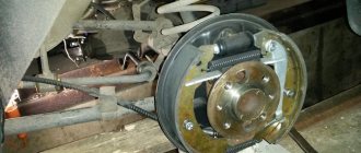
- Let's go further, now you will need to remove the oil seal from the gearbox socket where it is installed, for more detailed information on how to do this, read the article: “Replacing the VAZ gearbox oil seal”, but only there the whole process is shown on the installed gearbox and you have it removed, so keep that in mind.
- After removing the oil seal, there is an oil deflector in the socket where it was located, carefully pry it with your hand and remove it, or simply tilt the gearbox a little and it will fall on its own, but just do not deform it (see photo 1), immediately behind this oil deflector there will be another ring bearing with the same cage and rollers, remove it from the seat too (see photo 2) and then, on the other side of the gearbox (from the inside), use a drift to knock out the outer ring of the bearing (see photo 3) and be prepared for the fact that it it will fly out on the other side, so you need to knock it out either with your hand or with something soft (see photo 4), otherwise it will be all scratched and therefore you will have to replace it.
Removing the oil deflector from the gearbox socket, removing the bearing ring and knocking out the outer ring of the bearing located inside the gearbox
Note!
According to the instructions above, you knocked out the outer ring of the front bearing with a drift; knock out the outer ring of the rear bearing in the same way, but only knock it out from the other side of the gearbox!
- Next, if you need to disassemble the differential previously removed from the gearbox, then take the special puller that we talked about at the beginning of the article and use it to press along the shaft (in simple words, remove along the shaft means) the inner ring of the bearing as shown in photo 1, if the puller is such no, then use a chisel as shown in photo 2 to move the inner ring of the bearing a little (also hit in different places, so the ring cannot move and will move) so that two thick screwdrivers fit there, as soon as space for two screwdrivers is free, insert them sides and using it as a lever (see photo 3) completely remove the inner race of the bearing from the shaft.
Pressing the bearing inner ring
Note!
After removing the bearing race from the shaft, the same way you remove the inner race of another bearing!
- To work further, you will need a vice or something else you need to clamp the differential so that it does not move when you unscrew the driven gear fastening bolts (A vice is needed from soft metal jaws, if you don’t have such, then place a thick rag between the jaws and between the part and firmly clamp the differential already in this case, it is not necessary, everything should be neat), as soon as you secure it, unscrew all 8 bolts that secure the driven gear (for clarity, a couple of bolts are indicated by an arrow in photo 1), after unscrewing, take a hammer with a rubber striker or with a plastic one and knock it down driven gear from the differential (It is indicated by a blue arrow in photo 2).
Unscrewing the bolts securing the driven gear to the differential and knocking it down with a soft-faced hammer
- Well, in conclusion, we move on to disassembling the differential, first remove from it the axle (see photo 1) on which the satellites are located, then, turning the satellites by hand, remove them from the differential (see photo 2), after them remove the side gears ( see photo 3) and their support washers (see photo 4) and with this the entire disassembly is completed, below it is explained how to assemble all these parts and their troubleshooting is explained (Fault detection is checking parts for defects, it explains what you need to look for and when in which cases it is necessary to replace certain parts with a new one).
Removing the satellite axle and removing the satellites themselves from the differential, as well as removing the semi-axial gears and their support washers
Assembly:
- All parts are assembled in the reverse order, but before assembly they need to be washed in kerosene and inspected, so after washing, pay special attention to the gears, each gear has teeth, so they should not be damaged, should not be scuffed, and should not change color either be painted (they must have the color of the metal and no black scale from the oil), since this is unacceptable; in addition, with fine-grained sandpaper, clean the satellite axle, the axle gears, namely their journals and the seats of these gears from scratches and minor damage if they will wear out; if the parts are severely deformed, replace them with new ones.
Note!
When you disassembled the gearbox from there, at the very last moment you had to remove the support washers and before that the semi-axial gears, so the semi-axial gears, as you already understood, go as one with these washers, and if you find that the support washers are deformed (Even insignificant), then in this case, be sure to replace these washers with new ones, but keep in mind that they need to be taken exactly the same thickness as the old ones, so don’t be mistaken!
- Now check the differential bearings; in no case should there be deformations or various kinds of scuffs on their working surfaces; if they are present and thus the working surface is not smooth, then replace these bearings with new ones and by the way, they are the cause of constant noise during operation of the gearbox (This is if they are worn out).
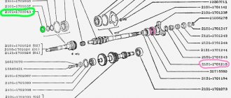
- When assembling the differential, the inner rings of the bearings, which you previously removed using a special puller, are installed with a piece of pipe of a suitable diameter until the rings rest, in addition, when assembling the differential, lubricate the side gears and their support washers with transmission oil, and also lubricate the satellites (One of the satellites indicated by number 9 in the diagram) and install all these parts back, during installation, rotate the satellites and side gears (One of them is indicated by a number
 so that the axis of the satellites can enter and install it after that.
The photo shows a diagram of the rear axle gearbox, but it is not complete, but with it you can understand everything perfectly
Note!
Also check the axial clearance of the axle gears, it should not be more than 0.1 mm, and if there is, then replace the support washers on all gears with washers of greater thickness, and if you can do anything else, determine the torque of the differential gears (By hand, these gears in case of determining the torque must be rotated as shown in the figure below), then this moment should not exceed more than 14.7 N.m (1.5 kgf.m)!
Rotate the differential gears and thus check the axial clearance of the gears
- Next, use a hammer and a suitable piece of pipe or a socket, with their help you will need to press (This means inserting) the outer ring of the front and rear bearings inside the housing (see photo 1), then if you decide to replace the main gear pair (The main pair includes the driven gear and the drive gear) or the bearings of the drive gear, then the adjusting ring will still have to be selected (Indicated by number 6 in the diagram above), to select it you need to make a device from the unnecessary (Old) drive gear, for this take a plate 80 long mm and weld it to the gear and after welding, grind it depending on the end of the gear to a size of 50-0.02 mm (see photo 2 in which the plate is already welded to the gear), then grind it or remove the layer of metal from that place with fine-grained sandpaper gears where the rear bearing is installed (indicated by number 5 in the diagram above), the metal layer must be removed until you achieve that the inner ring of the bearing is installed using a sliding fit; as soon as the required layer of metal is removed, install the inner ring with the cage and rollers on the gear, and insert it all into the gearbox housing (we install it in its place, it’s easier to say), after installing the same inner ring, but only the front bearing (The front bearing is indicated by number 4 in the diagrams above) with the separator and rollers, install the flange on its own put the seat on and rotate it so that all the bearing rollers are in the correct position, immediately after that tighten the flange nut with a torque of 7.9–9.8 N.m (0.8–1.0 kgf.m) and place the gearbox level and upright as shown in the third photo, then place the straight edge so that it touches the bearing beds along the same line and use a set of feeler gauges to determine the size of the gap between the straight edge and the same plate that you welded a little earlier (see. photo 3), write down this gap value somewhere or remember it and compare it with the deviation from the nominal position of the new gear (The deviation of the gear is written on it itself, it can be either with a plus or a minus sign, look for the location of this entry on conical part of the gear shank, see photo 4).
Pressing in the outer ring of the front bearing and installing a special drive gear, thanks to which you can find out how thick the adjusting ring will need to be installed
Note!
Now open the calculator or think everything in your mind, for example, you have a gap of 2.90 mm, and on the conical part of the gear tail there is -15 (This is the deviation of the gear from the nominal position), let’s first convert the gear deviation into millimeters for this: “-15 x 0.01 = -0.15 mm”, after translation we find out the exact thickness of the adjusting ring that we need, for this: “2.90 - (-0.15) = 3.05 mm”!
- Then remove the old gear with the plate welded to it, as well as the flange, remove both inner rings with cages and rollers, take the new gear and install the rear bearing inner ring on it (see photo 1) and then insert this gear into the crankcase gearbox, install a new spacer sleeve, the inner ring of the front bearing and the oil deflector, lubricate the working edge of the new oil seal with Litol-24 grease (For more details on how to install the oil seal and how to lubricate it, read the article linked above, this article is called: “Replacing the gearbox seal on a VAZ”) and install the gearbox flange in its place, stop this flange so that it does not rotate and begin to tighten gradually, then the nut securing it using a torque wrench, you need to tighten the nut until the torque reaches 118 N.m (12 kgf.m) as shown in photo 2, while tightening the nut, also check the moment of resistance of the bearings to rotation of the drive gear (the moment is checked with a dynamometer, this is shown in photo 3) and if it turns out to be less than 157 N.cm (16 kgf.cm) - for new bearings, and for bearings with mileage over 30 km. less than 39.2 N.cm (4 kgf.cm), but the tightening torque will not be exceeded, then leave everything without bringing the nut to a torque of 118 N.m (12 kgf.m), and if the torque turns out to be more than 197 N .cm (20 kgf.cm) - for new bearings and more than 59.0 N.cm (6 kgf.cm) for used bearings, then the very first time you pulled this nut, the bearing tension was exceeded, in this situation it needs to be replaced replace the deformed spacer sleeve with a new one and reassemble everything and adjust the tension of the central flange nut in the same way.
Hammering the drive gear ring and determining the torque of the gearbox flange
Note!
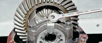
When assembling the gearbox, install the adjusting nuts (One of the nuts numbered 14 is shown in the diagram above for clarity) so that they come into contact with the outer rings of the bearings and then tighten the bolts that secure the left and right covers to the required torque (Install the covers according to the marks made earlier, since the left cover is different from the right), these adjusting nuts, by the way, can be rotated, thereby tightening and loosening them, for this, make a steel plate 49.5 mm wide and 3-4 mm thick and it is necessary to tighten these nuts, but to carry out this operation, adjustment you need to perform several points, the first is you will need to use a caliper to measure the distance between both bearing caps (see photo 4 above), after measuring you should get 0.15-0.20 mm, otherwise make the adjustment, to do this, screw the left adjustment slightly you made the nut with a special plate that you made earlier (see photo 1, the right nut is shown there, and the left adjusting nut is the one that comes from the side of the driven gear, the driven gear is the large gear), you need to tighten the nut until the gap is completely removed in the engagement of the main gears gear and then screw the right nut in the same way until it stops, then tighten the left adjusting nut a little until the lateral clearance in the meshing of the main gear gears is set at around 0.08-0.13 mm (This gap is difficult to check with anything, so it can be determined by touch, to do this, grab the driven gear with your hand and rock it with your hand, namely with your fingers, you will feel the very minimum play and the sound of teeth hitting when rocking should be heard), after setting the preload of the bearings, all using the same adjusting nuts, for this I can’t tighten both adjusting nuts evenly until the distance between the bearing caps is within 0.15-0.20 mm (see Fig. photo 4 above), after that, finally check the lateral clearance in the meshing of the main gears (It should not change), to check it, read the text just above described there and in addition to checking this clearance, grab the driven gear with your fingers and slowly turn it three turns (see photo 2) while using your fingers to control the backlash which should be minimal!
Checking the driven gear for backlash and adjusting this backlash using a special plate and adjusting nuts
Well, in conclusion, we will give some advice, these adjusting nuts regulate the gap between the driven and driving gears of the gearbox, so if this gap goes beyond 0.08-0.13 mm, then in this case, rotate the adjusting nuts and adjust it, if the gap is less position, then by tightening one of the adjusting nuts and loosening the second one to the same angle, ensure that it returns to its specified value!
Didn't find the information you are looking for? on our forum.