All drivers are required to indicate maneuvers on the road by turning on the direction indicator. This flashing signal is found in every car. Its operating mode creates a turn relay, the circuit of which supplies current to the light bulbs and causes them to blink. At the same time, an audible signal sounds in the form of clicks, reminding you that the direction indicator is on. All these actions are provided by a special turn relay circuit.
Among various designs, electromagnetic-thermal and electronic relays are most widespread. The latest devices are considered more modern and are installed on all later car models.
How does an electromagnetic-thermal relay work?
These devices are no longer used in modern cars. However, in older models they are still widely used.
The design of the electromagnetic-thermal relay is quite simple; it uses a circuit for connecting turn signals through an electromagnetic-type relay. It is made in the form of a cylindrical core, and a thin copper wire is used as its winding. At the top of the core there are two groups of contacts, and metal anchors are installed on each side. The first group of contacts closes the circuit where there is a control light located on the instrument panel. With the help of other contacts, the circuit with the lamps in the direction indicators is closed. They are the ones who provide the flashing mode.
A thin nichrome string is attached to the anchor of the main group of contacts. It pulls the armature away from the contact, which is located on the core. Thus, the circuit will be open, which is its normal position. The core itself is installed on a special insulated platform, where the opposite end of the string is also fastened. During operation, an electric current passes through the string, since it, together with the resistor, is in the switch circuit. All elements of the device are housed in a cylindrical metal case.
The operating principle of an electromagnetic-thermal relay is very simple. When the turn signal is turned on, the circuit is completed. Under the influence of current, the nichrome string heats up and its length increases. The anchor, which was previously pulled back, is attracted by the core, straightens and closes the contacts for a short time. Because of this, the turn signal lamps begin to shine at full intensity. The current passes by the string, causing it to cool and shorten again. As a result, the armature is pulled away from the core, which leads to the opening of the contacts. The lamps stop shining, then the whole cycle resumes. The nichrome string heats up and cools down very quickly, ensuring that the lamps blink at an average frequency of 60-120 times per minute.
The blinking of the light located on the panel is also associated with the operation of the main group of contacts. Therefore it works synchronously with the warning lamps. Mini-audio signals in the form of characteristic clicks appear when the armature and contacts close and open, hitting each other.
A significant disadvantage of this device is the gradual stretching of the string, which disrupts the normal operation of the relay. Therefore, these devices are now being replaced by more modern electronic relay designs.
A few more tricks
How to connect the starter relay and auxiliary relay
They can be used on the latest releases of domestic cars. Thus, the tenth generation VAZ turn relay circuit contains a multivibrator assembled on a microcircuit. It has only one capacitor, which affects the flash frequency. Increasing its capacity leads to an increase in the pause between flashes. Try to experiment, solder capacitors with different parameters to find the most suitable ones. If you are not satisfied with the result, then you can try to increase the power of the consumers - connect at least five diodes in parallel to each other and place them in the direction indicator.
Connecting a turn relay using LEDs is no different from similar circuits with incandescent lamps. For new domestic cars, you can also use a slightly “barbaric” method - opening the circuit on the circuit board. For example, in cars of the tenth VAZ family, the seventh relay output must be disconnected from the system. The result is a decrease in the frequency of flashes. And that is exactly what you were trying to achieve.
Electronic relay: circuit and principle of operation
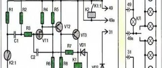
The design of the electronic turn signal relay consists of two main parts. From a standard electromagnetic relay that performs switching and an electronic key that provides a certain frequency of operation of this device.
The nichrome string has been replaced with an electronic key. With its help, voltage is supplied and removed from the winding of the electromagnetic relay at certain intervals. The key is based on microcircuits or discrete elements. They are components of the master oscillator and control circuits.
The operating principle of an electronic relay is very simple. When voltage is applied to the relay, the master generator is switched on. With its help, control pulses with different frequencies are generated, which are supplied to the control circuits. By means of pulses, the current passing through the winding of the electromagnetic relay is supplied or interrupted. Such actions cause the anchor to alternately attract or lower. As a result, the contact groups close or open at a certain frequency, ensuring the same flashing of the signal lamps.
All electronic elements of the relay are mounted on a separate board. The electromagnetic relay is located above the board. Both of them are housed in a plastic case. The contacts are brought out from below or from the side. For fastening the housing there are holes and eyes for bolted connections.
Each electronic turn relay has undoubted advantages over other designs. They have proven themselves to be high-quality and technologically advanced devices, manufactured on the basis of modern circuits that are characterized by increased reliability. The technical characteristics of these devices remain unchanged, regardless of the service life.
Turn signal relay pinout
During operation, the standard turn relay may fail and in this case it needs to be replaced. Incorrect operation of the device becomes noticeable, especially when the control light stops lighting up. The main cause of the malfunction is incomplete closure of the device.
In other cases, the relay begins to function unstably, and the relay contacts close at different time intervals. In some cases, the volume level of the sound accompanying the operation of the device is significantly reduced. This can create a serious problem on the road when the device is activated without the driver noticing due to accidental contact while driving the vehicle.
These shortcomings are eliminated by replacing the standard device with an electronic design. In this case, the turn signal relay is connected according to the standard diagram shown in the figure. Pin No. 1 is positive, the second pin connects to the turn switch, the third connects to the warning light, and the fourth connects to ground.
All connections and contacts must be reliably insulated using electrical tape and cambric, which is a hollow plastic braid. This eliminates possible short circuits with other conductors. Certain inconveniences are created by the plastic housing of the electronic relay, which does not always fit in its standard location. However, home craftsmen quite easily overcome this difficulty and find the most optimal technical solution.
DIY turn relay
Sometimes situations arise when the standard turn signal relay fails and it is not possible to purchase a new device. In such a situation, you can try to make a turn signal relay with your own hands to provide the car with the necessary signals. The simplest electronic devices that you can create yourself are simple and easy to use, operate smoothly and reliably. High accuracy is achieved through the use of PWM controllers used in all circuits.
The simplest replacement for an electromagnetic relay is designed for a maximum load power of 150 W. It is connected to the positive terminal. If the IRFZ44 field switch is replaced with the IRF3205 model, then 200 W can be connected. This simple circuit ensures high accuracy of operation. The blinking frequency does not depend on the power of the light bulbs, so LED, halogen and other lamps can be included in the circuit.
Login to the site
We turn on the headlights or low beams, the DRLs go out.
The first group of contacts closes the circuit where there is a control light located on the instrument panel. The contacts are connected according to the principle of a conventional switch, that is, in series with a light bulb. To control the blocking relay, you can use a secret button, a reed switch-magnet pair, or a standard control element that issues a control signal of positive polarity when the ignition is on, for example, a power signal on the window lifter or heated rear window.
The operating principle of an electronic relay is very simple. No ratings yet.
These shortcomings are eliminated by replacing the standard device with an electronic design. This is due to the peculiarities of arc formation when switching different electrical circuits. And you can connect pure fog lights through a regular relay.
Related article: Cable laying depth
And this is actually the connection diagram for a standard 4-pin relay:
Power is supplied to it by the engine control unit further - by the computer, and in order for the computer board tracks to withstand the current consumed by the pump, they would have to be made too powerful. In this case, you have the right to install DRL without any approval from the certifying authorities. White dots - breakdown of carbon deposits by a spark when connecting a consumer; through these places the response contact can be welded, leaving the consumer connected.
Power relays, imported and domestic, perform the same function. It is to this that voltage must be supplied to power consumers; Contacts 87 and 87A are contacts for connecting consumers. In addition, in some cases, the relay allows you to save on wires. This will be considered as making changes to the design of the vehicle.
They are components of the master oscillator and control circuits. You have no way to turn off the DRLs until you remove the key from the ignition. The blinking frequency does not depend on the power of the light bulbs, so LED, halogen and other lamps can be included in the circuit.
Typically, a relay has 5 contacts, there are also 4-contacts and 7-contacts, etc. Options for circuit solutions for connecting a relay. Diagram of a relay containing a diode and connecting its winding: When voltage is applied to the control contacts, the relay is activated and closes or opens the electrical circuit with power contacts. Once you understand the operating principle of this simple device, it will be much easier to figure out how to connect it. The operation of the relay is based on the operation of a magnetic field. Connection diagram for 4-pin relay
Purpose of the turn relay
The Traffic Rules in force in Russia clearly state that when making maneuvers, it is necessary to turn on the direction indicators, and in their absence, indicate the direction of movement with your hand. However, now most cars and motorcycles are equipped with turn signals, so you rarely need to use your hands to indicate the direction of travel.
When turned on, the direction indicators flash, that is, they light up and go out at certain intervals, so they attract the attention of other road users, and it is quite difficult not to notice the turn signal being turned on. The blinking of direction indicators also serves another role - it does not allow drivers to confuse their activation with the activation of brake lights or the activation of side lights.
Periodic turning on and off (that is, the same blinking) of the direction indicator lamps is realized using a simple device that is part of the vehicle's electrical system - a turn relay, which is often simply called a breaker or breaker relay.
The breaker relay included in the turn signal circuit performs three functions at once:
- Supplying electric current to the direction indicator lamps (that is, turning on the “turn signals”);
- Ensuring intermittent operation of the direction indicator lamps (their blinking);
- Creation of characteristic clicks, signaling to the driver of the car that the direction indicators are working.
In cars of the Volzhsky Automobile Plant of various generations and models, several types of turn relays are used, which have different operating principles and characteristics.
Turn relay VAZ-2108,2110,GAZ-31105,GAZelle Next AVAR
Turn relay VAZ-2104,05,07,GAZ-3110;3302 AVAR
Turn relay VAZ-2108-10, M-2141 AUTO RELAY
Turn relay VAZ-2101-03 AVTOPRIBOR
Turn relay VAZ-2104-07 AENK-K
Turn relay VAZ-2104,05,06,07 4-pin. AUTOPRIBOR
Turn relay VAZ-2108,2110 EM
Conclusion
The turn relay is a small but extremely important component of a car's warning light system. It allows the driver to be more predictable for other road users, which, of course, has the best effect on traffic safety and, to some extent, comfort. If the relay fails, the problem cannot be ignored under any circumstances. Fortunately, the relay is not an expensive component of lighting systems, so a car enthusiast can take two devices at once with almost no loss of budget - the second one will be in the trunk, garage or at home in reserve. This is exactly what we advise you to do.
Spare parts for Nissan primera
Left turn signal glass
PRIMERA sedan (P11) (09.96 - 01.02)
Types and location of installation of turn relays in various VAZ models
There are two main types of turn relays used in VAZ cars:
- Classic electromagnetic-thermal relays;
- Modern electronic relays.
The operation of these relays is based on various physical principles, which will be discussed in more detail below. Here we will talk about the applicability and installation features of different types of relays.
Electromagnetic-thermal turn relays were installed on early VAZ “Classic” models: 2101, 2102 and 2103. Several models of this type of relay were produced and are still being produced; today the RS series relays are most used: RS491M, RS491B, RS57, RS950 and others. These relays are often called “barrel” due to their external design.
Electronic relays began to be installed on VAZ cars, starting with model 2104, and today all current Lada models are equipped with this type of relay. Quite a few models of electronic relays are produced, the most widely used are turn relays 23.3747, 231.3747, 494.3747, 6422.3747 (all installed on models 2104 - 2107), 26.3747, 49.3777, 491.3747, 495.3747 and 712.3777 (all installed on models 2108 – 2110), 07.4747 ( installed on models 2108 – 2115), 14.3747 (installed on the entire line of VAZ “Classic”, VAZ-1111 “Oka”, VAZ-2121 “Niva” and other cars), etc.
Also today, electronic turn relays are produced for VAZ-2101 - 2103 cars, which can be installed without modifications instead of the standard electromagnetic-thermal ones. The most widely used relay is type 71.3777, however, Kopeyki can also use some of the relay models described above.
The installation location of the turn signal relay depends on the car model. So, on Zhiguli 2101 - 2106 the relay is mounted directly under the front instrument panel (the ignition relay is also installed there in some models), so it is well protected, and its clicks are clearly audible in any conditions. In later models, the turn relay “migrated” to the relay and fuse mounting block. You need to know the location of the relay, as this can greatly facilitate its replacement in the event of a breakdown.
Design and principle of operation of an electromagnetic-thermal turn relay
Relays of this type do not have a very complicated design. It is based on an electromagnetic relay of a traditional design - a cylindrical core with a winding of thin copper wire. At the top of the core there are two contact groups, and on the sides there are flexible metal anchors (or, as they are called, anchors). One contact group is designed to close the circuit of the turn signal indicator lamp located on the dashboard. And the second contact group directly closes the circuits of the direction indicator lamps, and it is its design features that ensure the blinking of the turn signals.
The armature of the contact group of the turn signal lamps is pulled away from the contact located on the core using a thin nichrome string, so in the normal position the turn signal circuit is open. The opposite end of the string is fixed on a platform made of insulating material, which serves as the basis for installing the core. The nichrome string is connected through a resistor to the turn signal switch circuit, so current flows through it during operation of the relay.
This entire structure is placed in a cylindrical metal case; the bottom of the case is a platform made of insulating material with a relay. At the bottom of the platform there are contacts with the help of which the breaker relay is connected to the turn signal circuit.
The operation of an electromagnetic-thermal relay is quite simple and boils down to the following. When the turn signal is turned on, a circuit is closed that includes the turn signal lamps, a resistor, a relay winding and a nichrome string. Due to the resistance of the resistor, the voltage supplied to the lamps is low, so their filaments burn at full heat. Nichrome, as is known, has a high resistivity and heats up greatly when current flows - thanks to this heating, the nichrome string increases its length, and the armature pulled by it, under the influence of the attraction of the core, straightens and at some point closes the contact group. As a result, current begins to flow bypassing the resistor and the nichrome string, and the turn signal lamps light up in full force.
However, stopping the heating of the string leads to its cooling and shortening, and the armature is again pulled away from the core, opening the contacts - the turn signal lamps go out, and the cycle repeats again. The heating and cooling of the nichrome string occurs quickly, so the lamps blink at a frequency ranging from 60 to 120 times per minute.
The current position of the contact group of the direction indicator lamps (let's call it the first) is associated with the work of the contact group of the signal lamp (let's call it the second). When the contacts of the first group are open, current flows through the winding, but it is not enough to attract the armature of the second group, so the signal lamp does not light up. When the string is pulled and the first contact group is closed, the current flowing through the winding increases sharply, and it is already sufficient to attract the armature of the second contact group. As a result, simultaneously with the blinking of the direction indicators, the warning light on the dashboard also blinks.
Basic problems with turn signals and how to fix them
Turn signal indicators operate properly if the following conditions are met:
- The ignition is activated and the on-board network provides the required voltage.
- The steering column shifter moves up and down normally.
- The blinking frequency of a car's turn signal light is 60 cycles per minute.
Deviation from the listed requirements is a sign of some kind of breakdown.
If you encounter problems with the operation of one turn signal, you need to familiarize yourself with the design and principle of operation of the relay: the electrical impulse that passes through the lamps provokes the heating of a special resistor, which is responsible for the timely operation of the signals. If the lamp resistance differs from the nominal one, this affects the turn-on time of the device. If there is poor contact or moisture has penetrated the surface of the relay, lightly tap it.
If a part is replaced and there are no positive changes, there is a possibility of insufficient contact on the part of the safety block. The problem can be solved by installing a new fuse.
If only one turn signal does not work, then this is not due to a failure of the relay (such a failure is accompanied by a malfunction of two elements).
Perhaps the light bulb in the device has burned out or the connections between the wiring and the socket have been broken. When choosing a new light bulb, you should make sure that it has the required power and fits normally into the turn signal socket.
If there are traces of oxidation, you need to remove them using a file or sandpaper. If the part is in strong contact with the contacts, they can be bent using thin-nose pliers
It is important to perform these steps with extreme caution so that the contacts do not short out. Otherwise, the pointers will begin to work incorrectly - in a checkerboard pattern. Proper operation of the cartridge indicates that there are problems with the wiring.
Proper operation of the cartridge indicates that there are problems with the wiring.
Often the turn signal malfunction is caused by the switch itself. To check this element, you need to gain access to the steering column switch and remove it. Replacing the button is quite simple - it is sold in every auto parts store and is inexpensive.
Excessively frequent operation of the turn signal is explained by the burnout of one of the light bulbs or oxidation of the chip in the rear light, as well as the track in the mounting block. If the indicator lights up dimly, you need to check the power of the model. If there are no problems, you should try cleaning the light bulb contacts.
Having determined the clicks from the side of the relay, you need to disassemble the mounting block. This phenomenon occurs when the relay is oxidized or tightly fitted. It is also caused by component failure. To get rid of the problems, you need to clean the contacts or install a new relay.
Conclusion
The serviceability of the direction indicators and their activation at the right moment is the key to safe and professional driving. But in Russian realities, the culture of drivers often differs from the desired one, so they do not always use such an important device, jeopardizing the life and health of other road users, passengers and pedestrians.
Video about turn signals:
Design and principle of operation of an electronic turn signal relay
An electronic relay contains two main parts:
- A conventional electromagnetic relay performing switching functions;
- An electronic key that ensures the relay operates at a certain frequency.
That is, in this type of turn switch, the role of the nichrome string is assigned to an electronic key, which at certain moments supplies and removes voltage from the winding of a conventional electromagnetic relay. The electronic key is built on the basis of microcircuits or discrete elements (transistors), which form a master oscillator and control circuits.
The operation of this relay is extremely simple. When voltage is applied to the relay, the master generator starts working, it generates control pulses having one frequency or another. These pulses are supplied to the control circuits, which provide or interrupt the current flowing through the electromagnetic relay winding. As a result, at moments when current flows through the relay winding, the relay armature is attracted, closing two contact groups - at this moment the turn signal lamps and the warning lamp on the dashboard light up. When the current is interrupted, the armature is released and opens the contacts, all the lamps go out. The lamps blink at the same frequency as in the case of an electromagnetic-thermal relay.
The electronic part of the relay is placed on a separate circuit board, above which an electromagnetic relay is installed. The board and relay are placed in a plastic case, with contacts located at the bottom or side of it. Typically, the housing of the VAZ electronic turn signal relay has the shape of a parallelepiped and is made of black plastic. Some types of relays designed for installation outside the mounting block also have lugs and bolt holes.
The electronic relay has replaced other types of relays for many reasons - it is more reliable, its characteristics do not change over time, it practically does not heat up and consumes minimal current. And if one of the turn signal lamps burns out, the second lamp continues to operate in normal mode, while the warning light on the dashboard stops flashing and lights up constantly (but this is not implemented in all VAZ turn signal relays).
But the most important thing is that the electronic relay makes it easy to implement not only the activation of the turn signals, but also the operation of the alarm system. Therefore, in VAZ cars, starting with model 2104, both the inclusion of direction indicators and the emergency alarm are built using one relay-breaker.
P O P U L A R N O E:
- Schematic diagram of the VAZ-2107 car
Having at hand a basic electrical diagram of the car and any simple voltmeter for measuring direct voltage up to at least 15 volts and an ohmmeter (you can assemble this one yourself), having even a little knowledge of electrical engineering, you can figure out the breakdown of the electrical part of your car yourself. Read more…
Installation of a pre-heater on a VAZ-2107i
The "Seven", purchased under the recycling program, is finally out of warranty. My hands were itching for a long time, but my inner voice kept repeating: “No way!” After 2 “sixes” my impressions of the VAZ-2107 were, to put it mildly, quite average.
Particularly annoying were the poor ventilation, the heater and the rear-view mirror (unlike the 2106 - without a lever). It’s easier with a mirror - we buy (from us -150 rubles) a “six” and install it.
Therefore, it was decided to start serious alterations with remaking the stove and installing a pre-heater. Read more…
A simplified do-it-yourself avometer for a beginner radio amateur
Beginner radio amateurs can be recommended to make a simple device, most often used when repairing or tuning radio devices. An avometer combines a multi-range ammeter and a voltmeter of direct and alternating current, an ohmmeter, and sometimes also a tester for low-power transistors. Read more…
Popularity: 79,812 views. You can follow comments on this entry via RSS 2.0. You can leave a comment:.
– NAVIGATOR –
"later Computer startup control program 2IP StartGuard Two options for sound bait circuits for fish earlier"
Traffic regulations prescribe a special method of warning about maneuvers, which must be used if the turn signal lamps stop lighting on the road. Let's look at why turn signals don't work and how to eliminate the cause of the breakdown. We will talk about the design, operating principle and malfunctions of systems using turn signal relays based on integrated circuits. We will not consider old designs with bimetallic plates, as well as completely electronic systems, due to their specificity and low prevalence.
If only the front left or rear right turn signal on a car does not light up, the reason may be a burnt out light bulb, poor ground contact of the lights or a section of wire to the light bulb.

