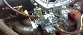
Air or a fuel-air mixture, depending on the type of engine (diesel, injection or carburetor), enters the cylinders through the intake manifold. The main purpose of the intake manifold is to ensure uniform distribution of air or working mixture between the cylinders. The efficiency of the motor directly depends on this. In addition, other components, such as a carburetor or throttle valve, can be mounted on the manifold.
The principle of its operation is quite simple: air or its mixture with fuel, entering through the inlet, is divided into several streams, according to the number of engine cylinders. The pistons, moving downwards, create a vacuum in the manifold, which can reach large values. This partial vacuum is also used to neutralize crankcase gases. They enter the intake manifold through the engine crankcase ventilation system, mix with the fuel-air mixture or air and are burned in the cylinders.
Until recently, the main materials for the manufacture of the intake manifold were aluminum, iron and cast iron. This created certain difficulties. The fact is that the collector itself gets very hot during engine operation and heats the air that is currently inside it. The air, in turn, expands and enters the cylinders in a smaller volume, as a result of which fuel consumption increases and engine performance deteriorates.
As an alternative to metal, since the late 90s, now the last century, plastic-based composite materials have been used on many cars. Due to low thermal conductivity, such an intake manifold does not heat up as much, as a result, the cylinders are better filled with air, and the engine power per unit of fuel increases.
Why does a car need an intake manifold?
The intake manifold has many tasks, but the main one is supplying air (lots of air).
Speaking in technical language, he is responsible for:
- Supply of air flow involved in the preparation of the fuel mixture in compliance with the ratios specified by the engineers;
- Uniform distribution of air into the cylinders;
- Use of VUT vacuum to enhance forces in the braking system;
- Operation of the crankcase ventilation system (CVG);
- Controlling the speed of the power unit at idle due to the operation of the throttle.
For each power unit, its own intake manifold is developed, the geometry of which will be optimally matched to the engine architecture.
Could one of the collectors break?
There are no units or parts in a car that cannot break.
So manifolds also do not last forever, although the exhaust usually lasts throughout the entire life of the car without requiring replacement. The intake one is less durable, especially if made of plastic; it may crack, and then the only option is replacement. Metal is much more durable, although it is not immune to cracks, but unlike plastic, it can be welded, which will solve the problem. Despite the primitiveness of the design (both manifolds are essentially pipes of a specific shape), without them the engine of a modern car will not be able to operate correctly, because they not only perform their direct functions, but also help greatly optimize the operation of the power supply and exhaust systems due to the information received to the ECU from the lambda probe. Both manifolds are interconnected and equally important to the car, and if they are not working correctly, you simply will not be able to drive your car properly.
We also recommend watching this video about the operation of the intake and exhaust manifolds:
Source
Device
Although from the outside the intake manifold appears to be just a pipeline of a specific shape, in fact a whole team of engineers works on its geometry, calculating the cross-section, length and volume.
Plus, it includes:
- Throttle valve;
- Supply chamber;
- Air filter;
- Inlet valve;
- Discharge chamber.
For engines with distributed fuel injection, injectors are additionally installed in the intake manifold, due to which the mixing of fuel and air masses occurs directly in the discharge chamber.
The pipeline itself can combine from 2 to 12 channels, depending on the number of cylinders in the engine block. At the same time, for a 4-cylinder engine, a manifold with three pipes is sometimes used.
It is also worth noting that most modern intake manifolds over the past 5 years have been made from special high-temperature plastic, while the exhaust manifold can still only be made from metal.
Installation and connection rules
It is best to select and install a collector at the stage of design and installation of the heating system.
Such intermediate structures are installed in rooms protected from excess humidity. Most often, space is allocated for these purposes in the hallway, pantry or dressing room.
It is advisable to place the collector block in a metal cabinet specially designed for this purpose, equipped with holes in the side walls for pipe outlets
On sale there are overhead and built-in models of metal cabinets. Each model is equipped with a door and stampings on the sides.
In the absence of the opportunity to install a metal cabinet, it is easier to do it by fixing the device directly to the wall. The niche for arranging the collector block is placed at a low height relative to the floor.
There are essentially no generally accepted instructions for installing collector distribution circuits. But there are a number of main points regarding which experts have come to a common denominator:
- Availability of expansion tank. The volume of the structural element must be at least 10% of the total amount of water in the system.
- The presence of a circulation pump for each laid circuit. Regarding this element, not all experts are unanimous in their opinion. But still, if you plan to use several independent circuits, it is worth installing a separate unit for each of them.
An expansion tank is placed in front of the circulation pump on the return line. Thanks to this, it becomes less vulnerable to the turbulence of water flows that often occur in this place.
If a hydraulic arrow is used, the tank is mounted in front of the main pump, the main task of which is to ensure circulation in the small circuit.
The location of the circulation pump is not important. But, as practice shows, the service life of the device is somewhat higher on the “return” route.
The main thing during installation is to position the shaft strictly horizontally. If this condition is not met, the very first bubble of accumulated air will leave the unit without cooling and lubrication.
The process of assembling and connecting the collector system is clearly presented in the video block.
Principle of operation
The intake manifold is connected to the air supply system. The wide part, where the pipes are located, is attached directly to the cylinder head.
After which, through the intake system, the air masses enter the supply chamber, where the air supply temperature can reach up to 120 degrees.
Then the air passes through the filter and the intake pipe, from where it enters the discharge chamber through the throttle valves, and from there, through the intake pipes, the air masses are sent straight to the cylinders.
This is interesting: What you need to know about car wheel alignment angles
A throttle, or simply a damper, regulates the cross-section of the pipeline, thereby controlling the speed and power of the engine.
How does the manifold affect engine performance?
When the engine operates at maximum speed with the gas pedal fully depressed, the speed of air in the manifold approaches (and in sports cars noticeably exceeds) the speed of sound. At such speeds, any turn and the slightest bump turn out to be a serious obstacle, which greatly increases the resistance of the collector to air flow. As a result, less air enters the cylinders, so engine power drops. In this mode, the carburetor often produces an over-lean mixture, the burning rate of which is tens of times faster than normal. Therefore, the air-fuel mixture explodes, which leads to damage to valves, pistons and other engine elements.
Equally important is a high-quality connection between the manifold and the carburetor or air filter. If the sealing elements are worn out or the fastening nuts are poorly tightened, then air leaks occur at the contact point, resulting in an over-lean mixture and explosions in the combustion chamber.
Changing the intake manifold geometry
As already mentioned, each engine has its own intake manifold geometry. This allows you to vary the speed and improve or worsen the combustion process.
In all cases, a change in geometry results in a change in airflow speed.
As you might guess, there are only three options for changing the geometry:
- Reduce or increase the length of pipes;
- Narrow or expand the cross-section of pipes;
- Combined approach.
Since it is often not possible to “play” with long pipes, they usually choose the second option - changing the cross-section. To do this, special dampers are used that regulate air flow differently than the factory mechanism.
Premium segment cars have a combined system for changing the geometry of the intake manifold.
These are precisely those cases when the manufacturer offers different options for driving modes, such as Comfort, Dinamic, etc. The change in engine characteristics is partly influenced by the operation of the intake manifold flaps.
Types of manifold pipe layouts
Exhaust manifold with 4-1 layout. It consists of four pipe-channels connected into one common pipe (the number of channels corresponds to the number of cylinders).
Tubular manifold 4-1
Exhaust manifold 4-2-1. In such collectors, pipes first connect cylinders operating in pairs (on the same stroke), and then move into one common pipe.
Exhaust system 4-2-1
An important parameter of exhaust manifolds is their length, and, accordingly, their volume. If the length of the exhaust channels is insufficient, the energy of the exhaust gas flows will be enough to enter the channels of adjacent cylinders and negatively affect their operation. In such collectors, the wave movements of gases are poorly synchronized with the operation of the engine. At the same time, engines with a short exhaust manifold typically have “narrow” valve timing with a relatively small volume of exhaust gases. The production of short-length collectors is justified by low cost.
One-piece 4-1 manifold with short exhaust ports
Long exhaust manifolds are used on powerful and efficient engines. In such manifolds, part of the volume of exhaust gases flows through a common pipe into the next components of the exhaust system, and part is “reflected” to the remaining cylinders. It will take much longer for the wave to pass from one cylinder to another, which creates definitely better conditions for discharge and purging.
Exhaust kit 6-2-1
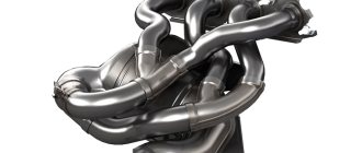
Exhaust manifold with equal length exhaust pipes (equal length). Typically installed on powerful sports cars.
Complex equal-length exhaust manifold made of pipes
An equal-length manifold allows for uniform exhaust in all cylinders and better synchronizes the operation of the engine with the exhaust system. Tuning the exhaust tract can be done on any engine. This is guaranteed to bring an additional 3-5% power.
The temperature problem is solved by installing thermal insulation. To do this, you can use a metal casing or a special non-flammable fabric.
There are models of collectors in which ceramic coating is used as thermal insulation.
Exhaust manifold cover
Collector channels insulated with special fabric
Exhaust manifold and turbine scroll with ceramic coating
Tuning
Tuning and changing geometry are two different things. When people talk about modifying the intake manifold, they usually mean increasing the incoming air volume and reducing the resistance along its path.
For this purpose the following procedures are provided:
- Replacing the air filter with a zero resistance filter. Thanks to the macroscopic holes in the latter, air is retained less and, accordingly, the speed and volume of passage increases;
- Enlargement of the throttle pipe. It also aims to increase air permeability. Usually, for this purpose, a damper is installed from another engine, which is more powerful than the original;
- Installation of a sports receiver. Short tubes with a larger cross-section, when properly configured, can reduce the pulsation of air masses, which allows the engine to gain speed faster.
There is also a tuning option when the intake manifold is completely removed and short pipes tuned to high speeds are installed instead. This option is provided only for naturally aspirated engines and is called a multi-throttle intake (that is, each cylinder essentially has its own manifold).
By the way, any changes in the intake system usually entail upgrading the exhaust manifold, camshaft and firmware of the electronic control unit.
Collector loads
Despite the fact that combustion products leave through the exhaust manifold, the temperature of the intake manifold in operating mode, even at half engine power, exceeds 100 degrees Celsius. When the engine is running, vibrations occur that negatively affect the condition of the intake manifold, so durable, vibration- and heat-resistant materials are used for its manufacture:
- cast iron;
- steel;
- aluminum;
- plastic.
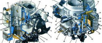
Differences in manifolds of diesel, carburetor and injection engines
The main difference between manifolds is that in a diesel engine only air passes through it, in a carburetor engine there is a fuel-air mixture, and in an injection engine the manifold participates in the formation of the mixture. Therefore, the intake manifolds of carburetor and diesel engines are simply a system of pipes with minimal aerodynamic resistance. And in injection systems they are some analogue of a Venturi tube, a conventional atomizer, in which the air flow carries liquid along with it and sprays it. This results in better atomization and mixing of the mixture than injection directly into the cylinder.
Malfunctions
Like any other mechanical part, the intake manifold is susceptible to failure. Given the simplicity of the design, there are not many options for malfunctions.
Basic:
- Violation of tightness. Vibrations, pressure and high temperatures destroy seals over time. Depressurization affects the quality of the fuel mixture, loss of traction and speed. The problem is solved by replacing the gaskets, after which engine operation should return to normal;
- Collector contamination. Plaque accumulates on the walls, gradually reducing the cross-section of passing air masses. Requires disassembly and cleaning of tubes, throttle and discharge chamber;
- Mechanical damage. If the collector is made of plastic, it is only a replacement. If it is made of aluminum and the damage is small, argon arc welding will help;
- Excessive temperature in the manifold. There are a lot of reasons and you need to look for them in the cooling system, clogged radiator, damaged sensor, ECU error. Also, high temperature occurs due to the banal heat outside;
- "Clap." When forming the fuel mixture, the system must be sealed. If there are disturbances in the ignition system, the gas distribution mechanism, problems in the fuel mixture formation chamber, or the tightness of the intake manifold itself is broken, you can hear those same pops. It is worth looking for reasons in all of the above places.
In the latter case, of course, it is easier to rely on the errors reported by the ECU or sign up for a comprehensive diagnostic service.
Is technology necessary?
The sequential formation of the intake tract, which is created by the throttle, filter, and valves, has a strong influence on the process of filling the cylinders with fuel. The air mixture that passes through this path fluctuates significantly. Together with other parts they form a shock system. This leads to the dependence of the processes of filling the cylinders on the factors of the oscillatory configuration.
Obtaining the efficiency of the system with the required parameters and the required range seems to be an extremely complex procedure. As a consequence, there is the idea of changing the performance of the oscillatory system during operation. After conducting research, it can be stated that the engine works well at high speeds with a short intake manifold. The opposite is true at low revs; efficiency can be achieved with a long intake tract.
It is logical that the conclusion arises to create an intake tract of variable length. This will allow them to be controlled taking into account different loads and speeds.
Collector pipe shape
Since precision must be maintained in the design, special attention is paid to the pipes. The channels must correspond to the exact parameters of length and shape; various curvatures and angles are not allowed in them. There are several reasons for this:
- fuel settling on the walls;
- Helmholtz resonance;
- calculation of pressure for system operation.
The first reason is simple, because fuel at sharp corners and protrusions will only settle on them. This can lead to blockages and narrowing of the channel in the future, so it is important to avoid such shortcomings.
The second reason is a common problem among designers. Helmholtz resonance is the resistance of air flow. When the intake valve opens, the mixture moves through the pipes to the cylinder. At the moment of its closure, the flow stops, but the inertia does not disappear. As a result, the mixture presses on the valve, creating high pressure in this area. With the same pressure it is pushed back, creating resistance during the next intake. As a result, the technical characteristics of the collector are significantly deteriorated, and many elements are subject to increased wear.
The last reason is the calculation of pressure for the operation of the system. If the length of the pipes is too long, the system will have to compensate for the pressure in this area for normal fuel movement, which leads to additional wear on the system.
Turbine
Another reason is a turbine malfunction. This structural element constantly circulates oil, which performs the function of lubrication and cooling. The turbine is located near the manifold, its task is to pump additional air, and it is due to this that it is possible to achieve an increase in engine power. But in some turbine malfunctions, it is the location that causes oil to appear in the manifold. It is worth noting that this problem is not the most serious, but a lot depends on the specific model, as well as the malfunction itself.
If there are problems with gaskets and seals, oil begins to enter the manifold during turbine operation. Moreover, this happens actively; there is quite a lot of oil. As a result, lubricant begins to spill through the top of the manifold. Actually, this malfunction manifests itself quite clearly. You can see how the oil is driven through the manifold, and the lubricant also appears on the spark plugs. Having seen this, you can safely remove and repair the turbine. Also, in the presence of such a malfunction, you may notice some dips when gaining speed, this affects the poor performance of the turbine.
Repair in this case will have its own characteristics depending on the car model. For some car models you can find repair kits for turbines. This will allow you to avoid unnecessary costs and quickly repair the unit; you can do this work, including yourself. But for some models the manufacturer does not produce repair kits for the turbine, which leads to the need to completely replace the part.
An article on the topic “Which is better - a turbine or a compressor?”
Inlet valve
Cold intake: pros and cons
The intake valve of the gas distribution mechanism allows access to the fuel-air mixture into the cylinder and stops access before the start of the compression stroke. In the case of a diesel engine, the valve allows only air into the combustion chamber.
When the timing belt breaks, the intake valves “hang” as the camshaft stops rotating. Valve plates that are open hit the surface of the cylinder
The valves are located at an angle of 30 to 45 degrees relative to the vertical axis. The intake valve plate is larger than that of the exhaust valve. The difference is due to the fact that at the moment the intake valve opens, a vacuum is formed in the combustion chamber, and at the moment of exhaust - increased pressure. The vacuum force is lower than the pressure force, so the intake requires valves with a larger head surface to ensure the passage of the required volume of the fuel-air mixture.
Design
This functioning of the intake system is ensured by the use of electronics. This means that all its constituent elements are divided into three main categories:
- Tracking devices (sensors)
- Control unit (ECU, also known as ECM)
- Actuators
The former monitor a number of parameters and, based on their readings, the ECU sends signals to the actuators, due to which the amount of air supplied is adjusted.
Audi RS4 intake system
There are quite a lot of tracking devices used in the design of the intake system. It includes sensors such as:
Audi RS4 intake system
- mass air flow or mass air flow sensor (mass flow meter);
- air temperature in the manifold;
- pressure (atmospheric, in the manifold);
- damper positions;
- EGR valve position.
This is a general list of monitoring devices that the intake system may include. In certain motor designs, some of them may not be present. For example, on some engines a mass air flow sensor is not installed, and its function is performed by a pressure sensor in the manifold.
The main ones of these tracking devices are the mass air flow sensor and the temperature sensor. They provide the control unit with information about the load on the power plant. The remaining sensors are auxiliary and provide information on the basis of which the ECU makes more correct decisions.
Manifold air temperature sensor
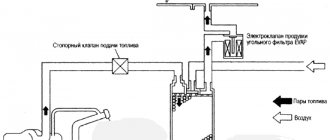
Since the intake system, like others, is controlled by the ECU, it is clear that it interacts with a number of them. Her work is “intertwined” with the systems:
- injection;
- exhaust gas recirculation;
- catching fuel vapors.
It also interacts with the brake system booster (vacuum).
Intake system elements
The design of the actuator includes a number of elements indicated above, as well as some others. It includes:
- intake;
- filter element;
- throttle assembly;
- collector;
- connecting pipelines;
- resonator.
In direct injection systems, the actuator also includes the intake flaps.
Manifold in the direct injection system of VW cars