In advertisements for the sale of a car you can find many offers of not new, but quite decent cars in good condition. As they say, “drive and ride.” But here’s the problem: the selected car has a carburetor. This is a rather old device, which scares off modern car enthusiasts, especially young people, due to its complexity, possible lack of repair parts and possible breakdowns. Whether to buy a car with a carburetor or find a more modern design with a fuel injection system - you can make a decision only after you understand the nuances of the operation and design of this device.
What is a carburetor and what is it for?
In order for an internal combustion engine to operate optimally, it is necessary to mix fuel and air in a certain proportion and feed this mixture into the combustion chamber. The mixture parameters can change depending on the operating mode of the internal combustion engine, fuel consumption too, which means you need a device that will do all this automatically.
A carburetor is a device for mixing air with fuel. As a result of its operation, at the right moment, atomized gasoline mixed with air enters the combustion chamber of the engine, ready for ignition. Despite the fact that there is only one carburetor for several cylinders, the mixture always gets to the right place through the intake manifold thanks to the coordinated operation of all internal combustion engine elements.
A little history of appearance
Inventors who lived in the 19th century began to equip equipment with engines that could run on gasoline or kerosene. They came to the conclusion that without air, fuel cannot ignite, and the air mass must be mixed with fuel in a certain ratio.
In 1876, an Italian inventor developed the first carburetor in history. The device worked in such a way that the fuel in it heated up, then evaporated, mixing with air. But a year later, other scientists were able to modernize the Italian’s development. They figured out how to make the fuel spray. It was on the basis of this principle that further developments were carried out.
Even before the creation of the first carburetor, scientists were developing various types of engines. Illuminating gas was used as fuel. It was expensive and also difficult to use. Only then was it replaced by liquid fuel, which needed to be ignited.
The carburetor patent was received in 1838 by William Bartner. But the car with a carburetor engine was “assembled” by mechanic Z. Markus. This happened 26 years later. The development and modernization of “carbs” continued. For example, at the beginning of the 20th century they created a device with a spray in the center of the air flow. In 1910, the legendary Solex was born. Further work was aimed at producing powerful engines with complex designs.
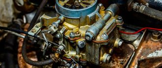
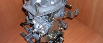
Carburetor design
To this day, we have received mainly float models - the latest and most improved. So you can find them on most cars.
Design of a float carburetor: 1 - adjusting screw of the starting device; 2 — lever pin 24, included in the groove of lever 3; 3 — air damper control lever; 4 — screw securing the air damper drive rod; 5 - adjusting screw for slightly opening the throttle valve of the first chamber; 6 — throttle lever of the first chamber; 7 — axis of the throttle valve of the first chamber; 8 — throttle drive lever of the second chamber; 9 — adjusting screw for the amount of idle mixture; 10 — axis of the throttle valve of the second chamber; 11 — throttle lever of the second chamber; 12 — pipe for suction of crankcase gases into the rear throttle space of the carburetor; 13 — throttle valve of the second chamber; 14 — outlet openings of the transition system of the second chamber; 15 — throttle body; 16 — sprayer of the main dosing system of the second chamber; 17 — small diffuser; 18 — fuel nozzle housing of the transition system of the second chamber; 19 — accelerator pump nozzle; 20 — fuel supply pipe to the carburetor; 21 — econostat sprayer; 22 — air damper; 23 — starting rod; 24 — air damper lever; 25 — starter cover; 26 — lever pin 24, operating from the rod 23 of the starting device; 27 — air damper axis; 28 — carburetor cover; 29 — tube with econostat fuel jet; 30 — fuel filter; 31 — needle valve; 32 — emulsion tube of the second chamber; 33 - float; 34 — main fuel jet of the second chamber; 35 — accelerator pump bypass jet; 36 — throttle valve drive lever; 37 — accelerator pump drive lever; 38 — accelerator pump diaphragm; 39 — adjusting screw for the quality (composition) of the idle mixture; 40 — vacuum intake pipe of the vacuum ignition timing regulator. 41 — carburetor housing. 42 - solenoid shut-off valve; 43 — adjusting screw for additional air for factory adjustment of the idle speed system; 44 - trigger diaphragm.
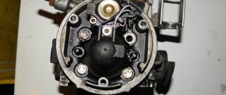
A float carburetor consists of many elements.
- A float chamber, which is responsible for maintaining a certain fuel level.
- A float with a shut-off needle, designed for automatic dosing of the fuel level in the float chamber.
- Mixing chamber in which the main mixing of atomized (fine) fuel and air occurs
- A diffuser is a narrowed area through which the air flow accelerates its movement.
- A nozzle with a nozzle connecting the float and mixing chambers, through which fuel passes directly to the diffuser.
- Throttle valve - regulates the flow of mixture entering the cylinders.
- Air damper - regulates the air flow entering the carburetor. Thanks to it, you can make the mixture “poor”, normal or “rich”.
Diagram of the dependence of power on the amount of air in the fuel mixture.
From the diagram it can be seen that a normal mixture is when there is about 15 times more air than fuel. Under such conditions, there will be complete combustion of gasoline and maximum power. - Idle system - supplies fuel bypassing the mixing chamber when the throttle valve is fully closed. Through special channels, gasoline and air pass into the throttle body.
- Economizers and econostats are devices for additional fuel supply when the engine is operating at maximum load. In this case, economizers have forced control, and econostats operate from air rarefaction.
- Fuel suction is a system for forced enrichment of the fuel mixture. By pulling the lever, the driver slightly opened the throttle valve, as a result of which air passed more intensely through the mixing chamber and took in more fuel. The result is a rich mixture, convenient for starting a cold engine.
Synchronization technology
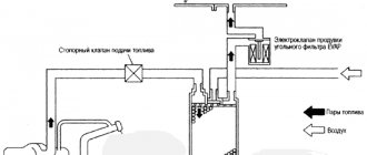
- Preparation . Before performing synchronization, it is necessary to adjust the throttle valve actuators. The gas tank is removed from the motorcycle; if provided for by the design of this model, the air filter is also removed. For some modifications, you may have to remove the carburetor assembly. Connections of measuring pipelines to the high-pressure pump are made through special vacuum ports, which are easy to find by plugs.
- Setting . After connecting the pipelines, it is necessary to warm up the engine and adjust the vacuum gauge valves for minimal fluctuations. If you release the valve, the device will respond more to changes in vacuum; when tightened, on the contrary, the arrows will fluctuate less.
Carburetors must be synchronized at XX speed, the value of which is set by the manufacturer. Therefore, you should first clarify this parameter in the instruction manual. Below we will consider the typical procedure for synchronizing carburetors. However, depending on the specific engine model, there may be some nuances.
On two-cylinder engines, synchronization is performed using a base screw, which controls the position of the cylinders 1 and 2. As a rule, it is located between the carburetors.
For four-cylinder units, in addition to the base screw, two adjusting fittings are additionally used. One screw for controlling the remote control in pairs of 1-2 and 3-4 cylinders. The third fitting is designed to control the remote control in cylinders 3 and 4, respectively.
- Synchronization . To synchronize carburetors, it is necessary to set equal values of vacuum in the air pressure chamber by rotating the screws. First you need to adjust the first fitting, then the third screw, and finally the second (central).
Synchronization of carburetors is considered completed if, after a sharp increase in engine speed and reset to idling mode, the arrows of all vacuum gauges show the same amount of vacuum.
The principle of operation of the carburetor
After watching the video below, you will clearly see the structure and principle of operation of the carburetor in different operating modes. The video, although old, is still relevant today. Don’t be lazy and watch to the end if you want to fully understand the topic.
Well, let’s summarize below - the operation of all float carburetors is carried out according to a typical scheme.
- Gasoline is pumped into the float chamber through the fuel line from the tank to the required level, which is regulated and maintained by a float and a shut-off needle.
- The sprayer, located in the lower part of the float chamber, uses a nozzle to transfer a strictly dosed portion of fuel to the mixing chamber. At the same time, the fuel flow is atomized for better mixing with air and combustion.
- The fuel from the atomizer is dispersed over a diffuser, which is designed to create a rapid flow of air and better mix it with the already atomized gasoline.
- The mixture of fuel and air flows to the throttle valve, which is directly connected to the gas pedal. The more fuel the engine needs, the more the throttle is open and the more active the carburetor is.
- From the carburetor, the fuel-air mixture passes through the intake manifold to the cylinder in which the piston is currently descending with the simultaneous opening of the intake valve.
- The piston works like a pump, drawing in the mixture already prepared in the carburetor.
Despite the rather simple operating principle, a well-tuned carburetor ensures excellent engine power delivery, good fuel economy and system reliability.
Mixing with air
The air is not pressurized, so constriction is necessary. Automobiles typically used a throttle valve. Then the accelerated air is compressed again in the diffuser, where it meets a certain dosage of fuel, which was sent from the tank to this part of the carburetor.
This mixture, and its amount, is controlled by a valve called a “butterfly” at the base of the device. This moving part is connected directly to the vehicle's accelerator.
Thus, the more it is open during operation, the greater the acceleration as rotation increases until the point of maximum power and torque is reached.
The throttle also operates a pump to move more fuel from the tank to the diffuser. When the engine is idling, the throttle valve is closed. In this case there is a very small metering needle, just to maintain the idle speed.
Inside the carburetor body are both externally adjustable fuel and air diffusers, where a mechanic or knowledgeable technician regulates the intake of air and fuel, balancing the mixture to improve performance.
Since it is a mechanical system, there is no way to balance the proportions and thus the carburetor only handles one type of fuel.
Types of carburetors
The predecessors of the float carburetor already discussed were the membrane-needle and bubbling carburetors. These are already outdated designs that today cannot be found on cars for everyday use (but these rarities still exist on “old cars”).
A needle-membrane carburetor consists of several chambers separated by membranes. The membranes rest on springs of a given stiffness and are connected to each other by a rod. The membrane chambers have an outlet to the mixing chamber and are also connected to the fuel supply channel. The movement of the rod activated the membranes of the chambers, causing them to pump fuel into the mixing cavity. Yes, the system is somewhat cumbersome and slow to respond to changes in engine operating mode, but at the same time it is reliable to such an extent that it was installed on aircraft engines.
Scheme of a membrane-needle carburetor
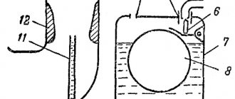
The bubble carburetor is the first design and the first attempt to create such a device. It was a blank lid that covered the gas tank at some distance from the fuel. Two pipes were connected to the cover: one inlet for air, the second to the engine. The air, passing under the lid, was saturated with gasoline vapor and in this form was sent to the combustion chamber. This is the first device designed to work with fuel vapors.
Diagram of a bubble carburetor: 1 - pipeline; 2 — hole in the float chamber; 3 — diffuser; 4 - sprayer; 5 - throttle valve; 6 - mixing chamber; 7 - jet; 8 — float chamber; 9 — float; 10 - needle valve.
The classification of other types of carburetors depends on the design features. Based on the cross-section of the nozzle, there are devices with constant vacuum (models made in Japan with the highest performance characteristics), with a constant cross-section of the nozzle (carburetors made in the USSR and the Russian Federation) and with spool throttling (horizontal carburetors, intended mainly for motor vehicles).
Based on the direction of movement of the finished mixture, designs with horizontal and vertical flow are distinguished (of the latter, the system with a downward flow turned out to be the most effective).
Float carburetors may have one or more mixing chambers. Single-chamber units were in use until the 1960s, when engine developments required increased carburetor capacity.
The creation of multi-chamber carburetors with multiple throttle valves solved this problem. Varieties appeared: carburetors with the simultaneous opening of two throttle valves, each of which fed certain cylinders, and carburetors with the sequential opening of two valves, which were connected to the entire engine and operated in accordance with its mode.
As engine power increased, so did carburetors. Three- and four-chamber types appeared, several carburetors were installed on the car, various options for preparing the fuel mixture were configured (for example, an over-enriched mixture was made in one chamber, and a lean mixture in the other two).
Advantages and disadvantages of carburetors
Only the deaf have never heard of the horrors of constant carburetor repair. But what really? What are the advantages of this device and is there any point in dealing with it at all? Strange as it may sound in our technological age, the carburetor has several serious advantages.
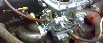
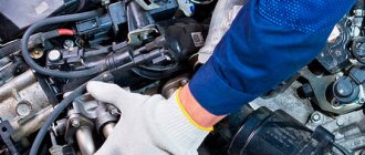
- Simplicity of design. No, the point is not that this is a very simple mechanism. But compared to the electronic components of today's cars, the carburetor is much easier to repair, maintain, and even operate. Most carburetors do not have any electronics, only mechanical devices, which means that a person with “straight hands” can repair and maintain it himself. The “old guard” – our parents, who are accustomed to delving into their “beloved” Zhiguli and Cossacks – remember this well.
- Maintainability. Anything that breaks in the carburetor can be repaired without “excess blood.” The necessary spare parts can be purchased (there are manufacturers that still produce repair kits. Why not?).
- When working with low-quality fuel, the carburetor turns out to be much more durable and stable than the injector. In general, it is not too demanding on cleanliness, and if it gets clogged, it can be easily cleaned at home (“garage”).
- A small amount of water entering the carburetor will not harm it, unlike the injector. However, over time it will require cleaning and calibration.
- And finally, the carburetor does not require connection to the electrical network, sensors, processor and other “joys” of civilization. It operates solely on the energy of the air sucked in by the engine, which means it was the best option for installation on older cars that had no electronics at all.
But there are also disadvantages due to which carburetor cars eventually disappeared from the world automotive arena.
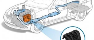
- Technology required a fuel supply system with flexible adjustments, rather than with constant parameters, in order to minimize fuel consumption (which no one had previously taken into account). Therefore, the carburetor was replaced by an injection system, which is still being developed and improved.
- The second significant disadvantage is the dependence of the carburetor on weather conditions. During the cold season, condensation collects inside, interfering with operation; in winter, there is a risk of icing of the inside. At the same time, the summer heat also prevents it from working stably due to active evaporation - disruptions in the supply of the mixture begin.
- Well, the third drawback is that the environmental performance is significantly lower compared to an injector. In the modern struggle for the environment, carburetor cars simply do not stand up to criticism, since their harmful emissions are much higher.
Let's sum it up
Carburetors, contrary to the opinions of most car enthusiasts, continue to work to the delight of owners of old cars. Cleaning and repair work is carried out by drivers themselves manually. This costs less than washing the injectors, which is carried out by those who own injection machines.
Some drivers are interested in the question of whether it is worth purchasing a used car with a carburetor. On the one hand, this is a reliable device that can not cause trouble for a long time. But on the other hand, the “carbs” are already outdated, and perhaps it’s time to switch to something more modern. Everyone decides this question for themselves.
| Tweet |
Main malfunctions of carburetors and their causes
Malfunctions in the carburetor are reflected in the operating mode of the engine, and it is by this that one can determine that not everything is normal with the fuel supply system.
- It is difficult to start an engine that is not warmed up - most likely, there are problems in adjusting the throttle valve. It is necessary to adjust the damper drive so that when the suction is extended, it closes completely, or adjust the starting clearances.
- An unheated engine starts and immediately stalls when the choke is fully extended - the problem, again, is in the throttle valve drive. Either the gaps are incorrectly adjusted, or the telescopic rod does not work and the damper does not open.
- A warm engine is difficult to start - the fuel level in the float chamber has not been adjusted, the float mechanism or valve needle has failed, resulting in the fuel level being higher than normal.
- Unstable engine operation at idle speed - there may be several reasons, and the main one is the adjustment of the idle system. Other reasons - the idle speed ecostat drive does not work or the shut-off valve does not work, the jets are clogged, air is leaking, the float in the float chamber is not working properly
- When opening the throttle, there is no increase in power - the mixture is too rich or lean due to the accelerator pump nozzle not being sealed.
- Low acceleration dynamics - lack of fuel due to a lean mixture or shutdown of the secondary chamber.
Components
All types of carburetors have different components. But modern devices have a number of common characteristics, including:
- Air channel (Venturi tube).
- Throttle valve.
- Idle speed solenoid valve.
- Acceleration pump.
- Carburetor chambers (primary, float, etc.).
- Float mechanism.
- Carburetor membrane for pumping fuel.
- Adjustment screws.