Every car owner strives to keep their car in optimal technical condition. And the more modern the car, the more difficult it is to maintain it yourself.
But many continue to actively drive cars with a carburetor engine under the hood. And the K126G can easily be considered among the popular and sought-after carburetor systems.
Moreover, the K126 has many modifications. And each of them is installed on certain vehicles. In this case we are talking about UAZ cars.
Design and adjustment of the K126G carburetor
The era of carburetor technology is long gone.
Today, fuel enters the car engine under electronic control. However, there are still cars that have carburetors in their fuel system. In addition to vintage cars, there are also quite workhorses - UAZs, as well as classics from the Togliatti Automobile Plant. This means that the ability to understand the device, carry out maintenance, and repair the carburetor remains valuable. This article will focus on the K126G carburetor. Adjusting the K126G carburetor is a delicate undertaking that requires certain skills and good knowledge of its composition and operating principles. But first, let’s remember a little about what a carburetor actually is.
About carburetor systems
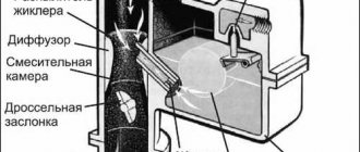
So, what is a carburetor? Translated from French, carburation means “mixing.” From here the purpose of the device becomes clear - to create a mixture of air and fuel. After all, it is the fuel-air mixture that is ignited by a spark from a car’s spark plug. Due to their simplicity of design, carburetors are now used on low-power engines of lawn mowers and chainsaws.
There are several types of carburetors, but in all cases the main components will be a float chamber and one or more mixing valves. The principle of the float chamber is similar to the valve mechanism of a toilet cistern. That is, the liquid flows to a certain level, after which the shut-off device is activated (for a carburetor this is a needle). Fuel enters the mixing chamber through a sprayer along with air.
A carburetor is a fairly delicate device to configure. The K126G carburetor must be adjusted with every maintenance and any problem. A correctly configured fuel-air mixture supply unit ensures uniform engine operation.
K126G carburetor design
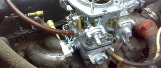
The K126G carburetor is a typical representative of the two-chamber version. That is, the K126G contains a float and two mixing chambers. And if the first one works constantly, then the second one starts to work only in dynamic modes with sufficient load.
The K126G carburetor, the device, adjustment and repair of which are described in this article, is quite popular for UAZ cars. The device is very unpretentious in operation and is resistant to debris.
The K126G float chamber has an inspection window from which you can determine the fuel level. The carburetor has several subsystems:
- idle move;
- starting a cold engine;
- accelerator pump;
- economizer.
The first three operate only in the primary chamber, and for the economizer system a separate nozzle is provided, which is discharged into the air channel of the second chamber of the carburetor. General control of the device is carried out using the “choke” system and the accelerator pedal.
Applicability of K126G
A carburetor marked “K126G” was installed and is still serviced on Gaz-24 “Volga” and UAZ vehicles, with mainly UMZ-417 engines. UAZ car owners especially love this model for its unpretentiousness and ability to work even with clogged fuel.
With minor modifications (drilling a hole), the K126G is installed on UMZ-421 engines. And this could be either a UAZ or a Gazelle. The predecessor of the K126G can be considered the K151, and the next model is the K126GM.
Adjusting the K126G carburetor is the most popular question among carburetor technicians. But first, let's look at various problems that can happen with the K126G.
Modifications of K126 carburetors
Carburetors of the 126th series have been produced for decades; the first models were manufactured at the Leningrad plant (Lenkarz), later renamed PEKAR. They began to be used on GAZ-53 and GAZ-66 trucks starting in 1964 (K126B), in 1977 the GAZ-52-03 was equipped with the K126I model, and the “Gazonchik” 52-04 began to be equipped with the K126E. The K126D version was also developed for Lawns and PAZ buses; later GAZ trucks began to be equipped with a K135 carburetor, which, in fact, is an analogue of the “one hundred and twenty-sixth”.
The K126P modification was intended for four-cylinder MZMA engines, used on Moskvich-408 cars, production began in 1965. The K126N modification was already used on Moskvich-412, for the Volga 24 and 24-10 the K126G and K126GM (the modernized version of G) were intended, and for cars with gas equipment - the K126S. The model used regularly on UAZs is the K126GU version (UMZ-417 engine), often UAZ owners install a Volgov carburetor “G” or “GM”.
In fact, many variants of the “126” are interchangeable, differing mainly in the lower part of the body (“sole”) and the top cover (different mounts for the air filter housing). Of course, each of the carburetor units is equipped with its own jets, but they can be easily changed. The only thing that cannot be done is to install a carburetor from a truck to a passenger car, and also in the reverse order, here they have significant differences.
Source
Possible faults
All malfunctions of the described system are either visible visually or are easy to check. One of the main problems is unstable operation of the engine at idle, or there are no idle speeds at all. The K126G carburetor, whose fuel flow adjustment is normal, allows the engine to idle without any problems.
The second point that shows that the device is faulty and requires adjustment is an increase in fuel consumption. There may be several reasons, so adjusting and tuning the carburetor does not always help.
Planned regular cleaning of all components can solve the problem. Incomplete cleaning is also possible when the carburetor is not removed from the car, but it is undesirable. K126G, like any mechanical device, prefers good care.
Adjusting the K126G carburetor
The need to adjust the carburetor may arise for various reasons. This could be routine maintenance or troubleshooting issues. Moreover, simple adjustments according to the instructions are quite easy to perform. The downside is that it does not always help in solving. Experienced mechanics with extensive experience in carburetor repair do not begin work without adjusting the valves.
In order for the fuel-air mixture mixing device to function without interruption and not require constant adjustment, timely maintenance is necessary. It is enough to carry out a basic inspection for leaks and tightness and flush the carburetor at least partially. Sometimes it is necessary to check the fuel level in the float chamber, as well as the flow rate of both fuel and air jets.
If we approach the issue systematically, then it is necessary to highlight the following types of carburetor settings:
- idle move;
- fuel level in the chamber with a float;
- economizer valve.
Adjusting the K126G carburetor on an UAZ most often involves adjusting the idle speed specifically. So, let's consider the sequence of actions to restore auto stability at idle.
Facts from history
Since 1968, the PAZ-672 model began to be produced at the Pavlovsk Bus Plant. In the seventies, modification 3201 came off the assembly line, and then 3205. The engine in these buses was similar to what was previously used in trucks. However, the motors were equipped with additional elements. As for the power system, no changes were made to it, so carburetors from the 126 series were used here too.
But it was impossible to immediately switch to new power units due to the appearance in 1966 of the GAZ-52, in which a six-cylinder engine was installed. In 1977, the single-chamber carburetor on this engine was replaced with a K-126 carburetor. Later, an almost exact copy of K-126 appeared - K-135. Now carburetors of the 126th family are practically not used on PAZ buses with ZMZ engines. But they have not completely gone out of use. And in this regard, owners have questions that need to be answered. The fact is that the 126th series was installed on Volgas, as well as on UAZs. Therefore, it is necessary to consider the design of these units, the main faults, and configuration methods.
Instructions for adjusting idle speed K126G
The stability of the engine is adjusted using two screws. One determines the quantity of the fuel-air mixture, and the second determines the quality of its enrichment in the K126G. Adjusting the carburetor, the instructions for which are given below, is carried out in stages:
- With the car turned off, tighten the mixture enrichment screw until it stops, and then unscrew it 2.5 turns.
- Start the car engine and warm it up.
- Use the first screw to achieve neat and stable engine operation at approximately 600 rpm.
- The second screw (enrichment of the mixture) gradually depletes its composition so that the engine continues to operate steadily.
- With the first screw we increase the number of revolutions by 100, and with the second we reduce them by the same amount.
Installation
First of all, we dismantle the air filter. Next, we remove one by one:
- damper drives;
- hoses (fuel supply and vacuum corrector vacuum extraction).
The unit is mounted on the flange of the engine intake pipe. four nuts. Additionally, spring washers are used. We check the integrity of the rubber gasket, if necessary, change it. At the final stage, we attach the damper drives and pipes.
Setting procedure:
- We check the tightness of the unit (special attention to the areas where hoses are attached, plugs and gaskets). If we find a fluid leak, we fix the problem;
- pump in fuel (6–8 times using a manual fuel pump);
- close the air damper, start and warm up the engine;
- as the engine warms up, gradually open the damper;
- at the moment when the antifreeze temperature reaches +40 °C, fully open the damper;
- screw in the screw that regulates the quality of the fuel mixture until it stops;
- unscrew the “quality” screw 5 turns;
- bring the liquid temperature to 90 °C;
- increase the crankshaft speed to the maximum possible amount;
- smoothly tighten the screw for adjusting the amount of fuel mixture until interruptions in engine operation begin;
- unscrew the “quantity” screw half a turn;
- We check the performance of the engine. We press the gas pedal and then sharply release it. If the engine stalls, increase the speed.
Adjusting the fuel level in the float chamber
Over time, it may happen that the level of gasoline in the float chamber changes. According to the norm, it should fluctuate within 18-20 mm from the bottom surface of the connector, which is determined through the carburetor inspection window. If visually this is not the case, then adjustments need to be made.
Changing the fuel level in the K126G chamber is carried out by bending the tongue of the float lever. This is done very carefully, trying not to damage the seal washer made of special gasoline-resistant rubber.
Cleaning procedure
Since adjusting the quality and quantity screws turned out to be ineffective due to contamination of the carburetor, it had to be disassembled and then cleaned.
Basically, carbon deposits and contaminants are formed in the jets, air dampers, as well as in the tank of the chamber with a float.
Each listed element should be washed, cleaned and blown after removal.
There is a special approach to jets. If you even slightly change the surface or damage the elements, the engine will not operate stably. The surface of the plugs must not be washed. Copper wires and toothpicks should be used for cleaning. Try to clean so as to minimize contact with the metal surface.
After finishing cleaning, blow out the jets with compressed air. You can take a regular can or a compressor.
Such a delicate attitude is not required for the air damper. It is usually placed with other metal elements in a container, filled with solvent and soaked for 2-3 hours. Then it is important to thoroughly dry and blow everything.
The float chamber can be cleaned of all contaminants fairly quickly. To do this, carburetor cleaner is poured inside. Let it brew and perform its functions. Usually 1.5-2 hours is enough. Then take a lint-free rag and wipe down all the cavities. It would be a good idea to blow out the assembly using compressed air.
Now the entire system is assembled in reverse order. The gasket may need to be replaced.
After assembly, a test run of the engine is performed. There is a high probability that after disassembling and reassembling the carburetor will not work perfectly. Therefore, it will be necessary to make adjustments using the quality screws and the quantity screw.
Advantages and disadvantages of K126G
The K126G carburetor is quite popular among UAZ owners. It is valued for a number of advantages that are missing from more modern models:
- stable operation in the presence of clogging;
- unpretentiousness to fuel quality;
- sufficient economy.
The K126G carburetor, the mixture quality of which is adjusted regularly, will work without any problems. Simplicity of design is a guarantee of reliability. In this case it will comply, but subject to scheduled maintenance.
The K126G has one unpleasant drawback. If overheated, the device body may become deformed. This occurs when the carburetor threads are over-tightened.
Design and procedure for adjusting UAZ K126G carburetors
The current condition of the vehicle is the main criterion for the performance of the machine components. The engine is considered one of the most important components of a car. UAZ models are equipped with carburetor-type power units (for example, the K126G carburetor), due to which the operation and adjustment of this type of vehicle is greatly facilitated in any mode of use.
Additional Tips
The k126g device is best cleaned using Mole. At the same time, in K126g you need to carefully monitor the condition of the jets. They are very fragile in it. For greater efficiency of the K126g, craftsmen bore the diffuser diameter to 27 mm. This gives the engine agility compared to the standard K126g.
The k126i device was installed on the GAZ 52, the engine of which had 6 cylinders. The K126i was designed specifically for this car. The diameter of the K126i diffuser was only 23 mm, which is not enough for such an engine. This carburetor gives more agility than the K126gm, but is still not sufficient for this car. So k126i needs to be modified independently.
K126 was installed on Muscovites. All advice from car enthusiasts regarding the K126 device boils down to replacing it. By upgrading it can be converted to 126n. So the Soviet people did not favor the usual K126. Nevertheless, there are Muscovites that are still in excellent condition and running. This speaks volumes about the quality of the machine, one of the components of which is the K126.
The k126n device is ideal for a Muscovite car. K126n is a little harder to set up, but this does not make it less popular. Many car enthusiasts prefer k126n.
K126G carburetor design
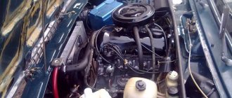
Cars of the UAZ family are equipped with three types of carburetors. Each of these types has its pros and cons:
The most common equipment for off-road vehicles of the UAZ brand is a carburetor of the K126G type . This model is the basic equipment for the UAZ “Bukhanka” vehicles, and is also an invariable attribute of the equipment of the UAZ “Hunter” and UAZ “Patriot”. A carburetor of this type is ideally combined with the UMZ 4178.10 and UMZ 4218.10 power units.
A simple device for equipping power units of domestic off-road vehicles
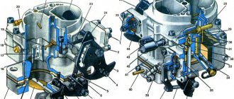
The K126G carburetor consists of several main components:
fuel metering device for the first chamber;
fuel metering device for the second chamber;
idle mechanism.
In addition to them, the carburetor includes many small elements, each of which is designed to perform highly specialized work in the overall system.
The clear interaction of various elements allows you to achieve high carburetor performance
The K126G carburetor is equipped with two chambers for mixing the air-fuel mixture. After turning the ignition key, fuel begins to form in the first chamber, then, with increasing torque, in the second. Various elements of the system allow strictly limited amounts of liquid fuel and air to pass through to create the air-fuel mixture in the required quantity.
If the engine requires a higher mixture content at maximum speed, then the economizer is switched on. The solenoid valve increases air flow through a constantly open air damper, which ensures the creation of a rich mixture for the engine.
Connecting hoses
The complex structure of the K-151 is also evident when it is connected to the engine. It provides for the use of a whole range of hoses, but only two different sizes are used, so it is quite possible to confuse them, and the motor will malfunction in certain modes. The order of connecting the hoses to the carburetor:
- Fuel is supplied through the fuel pipe to a fitting located under the float chamber on the engine side;
- the return hose is put on the lower fitting - it looks in the direction opposite from the power unit and is located below the inlet;
- two small cross-section hoses are connected to the solenoid valve, the other end of one of them is connected to the economizer valve;
- the second end of the thin hose is put on the fitting located in the lower part of the K-151 on the back side of the DZ body (there are two of them standing next to each other, we use the lower one);
- onto the upper fitting of this pair we pull the hose that goes to the vacuum ignition advancer (it is located on the distributor);
- a large diameter fitting on the DZ housing is used to connect the forced crankcase ventilation pipe, a device usually located on the valve cover;
- a small diameter fitting located in the middle part of the K-151 is used to connect a thermal vacuum switch, however, this pipe is used only if the engine has an exhaust gas recirculation system. If such a system is not provided for a particular modification of the motor, a plug is simply installed on this fitting. True, such a precaution is unnecessary - there is no air leak through this fitting.
If you lack experience, these connections should be made by consulting the instructions for the device.
Connecting carburetor hoses K-151D
The process of adjusting K126G on the UAZ “Loaf”
Adjustment as a procedure may be required only to eliminate some malfunctions in the carburetor or to adjust for greater productivity. Adjustment can be carried out according to a variety of parameters to achieve optimal performance of the K126G carburetor:
stability in the operation of the accelerator pump;
setting a new minimum idle value;
quality control of fastening connections in the UAZ carburetor;
reduction of fuel consumption in different operating modes;
increasing/decreasing the specified fuel level in the float chamber;
checking the effectiveness of economizer operation;
adjusting the throughput of the jets.
It must be borne in mind that adjustments to any of the parameters are carried out only with the engine turned off. In different cases, you will need to wait for the power unit to cool down or, conversely, start the engine to adjust the required parameters.
For example, most often car enthusiasts adjust the fuel mixture consumption. The K126G device is designed in such a way that there is no need to disassemble the carburetor - all necessary work can be performed directly at the installation site of the mechanism.
Video instruction: adjusting K126G
Fuel consumption adjustment
There are two small quality screws on the carburetor body. Each of them controls the supply of a high-quality fuel mixture to the engine cylinders. And on the side of the throttle valve drive there is one separately located screw - it is called the quantity screw and is responsible for the required volume of fuel that is supplied to the power unit.
The procedure for adjusting the fuel mixture flow involves using these screws in the following sequence:
On a cold engine, tighten the quality screws until they stop.
After that, unscrew each of them exactly three turns.
Start the car and wait until the engine reaches its operating temperature.
How to Correctly Adjust the Carburetor Gas 53
Adjusting the GAZ-53 carburetor
The GAZ 53 carburetor has a two-chamber system, each of which operates on 4 cylinders. The throttle valve is equipped with a drive for both chambers at once, so fuel is dosed synchronously to all cylinders. To ensure rational fuel consumption at different engine modes, the carburetor is equipped with several systems for regulating the composition of the fuel mixture (FM).
This is what the carburetor installed on a GAZ 53 looks like
The carburetor was originally brand K126B, and its subsequent modification was K135 (K135M). Fundamentally, the models are almost no different, only the control scheme of the device has changed, and on the latest releases a convenient viewing window was removed from the float chamber. Now it has become impossible to see the gasoline level.
UAZ carburetor repair
Owners of UAZ cars, if they have the necessary experience and knowledge, can carry out some types of repair work on the carburetor themselves. After the carburetor has been removed and disassembled, you can repair its parts without going to specialized auto repair shops.
Many UAZ car owners are faced with the problem of carburetor flooding. That is, the device produces too much air-fuel mixture, which does not have time to get into the engine.
If the carburetor is flooded, it will be necessary to check the functionality of the economizer needle, and also make sure that the calibrated holes of the jets have not enlarged.
If the engine starts to twitch at high speeds or idles unstably, it is recommended to check the solenoid valve or economizer.
Repair of the UAZ K126G carburetor is entirely based on washing the components and replacing worn parts. At the same time, only three factors can be considered the key to quality repairs:
careful disassembly of the device;
assembly taking into account all the nuances of the K126G design.
Video instruction: modernization and repair of K126G
Troubleshooting
The K126G carburetor has its own characteristic faults. As a rule, they are all related to the fact that, for a number of reasons, the throughput of the jets is reduced, the life of the accelerator pump is exhausted, or gaps appear when the throttle valves operate. In addition, as with any other carburetor, the K126G may also experience an unbalanced idle speed, due to which the engine may flood or experience a lack of fuel.
The obvious reasons that certain malfunctions have appeared in the carburetor are:
a sharp increase in the amount of liquid fuel consumed;
at high speeds the engine operates jerkily and intermittently;
there were difficulties starting the engine;
uneven operating noise and increased vibrations during movement;
black exhaust smoke with a sharp increase in speed or during braking.
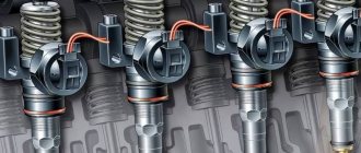
In carburetor mechanisms of any type, jets play an important role. According to their function, jets are plugs with several holes of clearly defined diameter. Air or liquid fuel enters through these holes, which guarantees the timely formation of the air-fuel mixture. Due to the use of low-quality gasoline, the jets can become clogged, causing the engine to lack fuel.
The main feature of the K126G carburetor is that all jets, regardless of their installation location, can be cleaned without dismantling. That is, in order to eliminate blockages in the holes, you will not need to completely disassemble the carburetor, since the jets are removed individually from the body of the device.
Table: performance characteristics of jets in different carburetor systems
| Carburetor elements | Nozzle capacity. cm 3 /min | Nozzle hole diameter, mm |
| Primary chamber | ||
| Main fuel jet | 240 ±3 | 1,05 |
| Main air jet | 195±4 | 0,94 |
| Idle fuel jet | 50 ±1,5 | 0,45 |
| Idle air jet | 285±7 | 1,15 |
| Acceleration pump nozzle | — | 0,6±0,06 |
| Accelerator pump with a capacity of at least 10 strokes | 5 | — |
| Secondary camera | ||
| Main fuel jet | 280 ±3,5 | 1,14 |
| Main air jet | 390 ±9 | 1,36 |
| Main jet of the transition system | 95±2 | 0,64 |
| Air jet of transition system | 285 ±7 | 1,15 |
| Economizer jet | — | 1,7 ± 0,06 |
| Economizer Sprayer | — | 3±0,06 |
Car owners of UAZ “Loaves” respond to the factory jets of the K126G carburetor:
It is better not to replace the jets with jets from repair kits. They won’t do anything for a hundred years, unless of course you scratch them with a nail) look at: opening of the dampers (are they fully open), accelerator pump (injector, pump itself), economizer, and of course the main dosing system
Mich
Conclusion
Despite its “venerable age”, the K-126 carburetor continues to be used. The reasons are simplicity, reliability, ease of maintenance. A minimum of effort is required, and the unit will work smoothly for years.
Maybe you know some special methods for tuning the K-126 carburetor? Share your experience in the comments. Pass on your skills to young car enthusiasts.
Installing a K 126 GU carburetor, instead of the standard K 151, on a UAZ Bukhanka car
remove K 151
and install a normal carburetor K 126 GU, at the moment this is exactly what is needed on this car:
will need it!
adapter sleeve or angle, you can use a gas line hose with a metal fitting on lawns, grooves, zils, etc. of trucks...
Or you can put a fitting under the hose from the fuel pump, they are sold both as a set and separately
here is the kit:
in the photo the fitting from the fuel pump is screwed into the adapter sleeve with a tapered thread:
You will also need a fitting for a vacuum corrector, it is not included, which is a big minus for manufacturers to 126!
They may sell something similar in spare parts for carburetors, but I have never seen in real life a fitting for the vacuum corrector hose coming to the distributor...
therefore, something suitable is selected, in our case it is an ordinary grease fitting, sanded down on the seat and installed:
unscrew the old long studs and put short ones in their place,
we install the carburetor, tighten the throttle linkage, tighten the air filter - it all fits without modifications!
if small ventilation is needed, then unscrew the plug on the intake manifold, screw a suitable fitting into it, calibrate the 3mm hole and connect it with a hose to the nipple of the air filter housing... in my case, a loaf for the forest, it cannot be driven or driven on the highways, so for now we have managed without a small one ventilation...
photo of the installed carburetor for 126 gm:
No extra parts are needed for the carburetor!
You only need to connect gasoline and a vacuum corrector to control the ignition angle of the distributor - EVERYTHING!
works EXCELLENT, traction at slow speed is smooth and stable, idling is smooth and stable, starting hot is easy...
cold start with the air damper completely closed (that is, the choke is extended) it starts perfectly and in the first few seconds the damper is slightly opened, otherwise it will get rich and flood, but these vagaries are individual on any car with its own...
Carburetors K-151V are used to complete the UMZ-4178 engines, and K-151U are used to complete the ZMZ-4021.60 engines. The K-126GU carburetor is used to complete the UMZ-417 engines, as an option to replace the K-151V carburetor.
In principle, the K-126GU carburetor is similar to the K-151V carburetor, but has a simpler design in which there is no forced idle economizer system and a float chamber ventilation valve.
Carburetors K-151V, K-151U and K-126GU for UMZ-417 and ZMZ-4021.60 engines, device.
Carburetors are vertical, emulsion, two-chamber, with a falling mixture flow and sequential opening of the throttle valves. All carburetors include:
- a balanced float chamber, - two main dosing systems - the first and second chambers, - an autonomous idle system in the primary chamber with quantitative regulation of a mixture of constant composition with a forced idle economizer (EPCH), - transition systems of the primary and secondary chambers, - an econostat with output to the secondary chamber, - a diaphragm accelerator pump with a mechanical drive from the throttle shaft of the primary chamber and with a spray nozzle output to the primary chamber, - a semi-automatic system for starting and warming up the engine with manual control, - in addition, the K-151V and K-151U carburetors are equipped float chamber ventilation valve.
Maintenance of carburetors K-151V and K-151U.
It consists of periodically checking the reliability of fastening of the carburetor and its individual elements, checking and adjusting the fuel level in the float chamber, adjusting the low speed of the engine crankshaft, cleaning, purging and flushing carburetor parts from tar deposits, checking the throughput of the jets.
Checking the fuel level in the carburetor float chamber.
It is carried out with the car engine not running, installed on a horizontal platform and with the carburetor cover removed. The float chamber is filled with fuel using a manual pumping lever.
The fuel level should be within 20-23 mm from the plane of the float chamber connector. To check it, you need to screw in a fitting with an M10x1 thread to connect the rubber hose. The fitting is screwed into the float chamber instead of the drain plug. The fuel level is determined through a transparent tube with an internal diameter of at least 9 mm.
The level is adjusted by bending the tongue of the float loop to a size of 10.75 -11.25 mm between the top of the float and the plane of the float chamber connector; the float should be raised to its highest position. In the lowest position, the float should not touch the walls of the float chamber, and its tongue should be on stop A. In this case, the stroke of the fuel valve should be equal to 1.5 + 0.5 mm. The valve stroke is adjusted by bending the tongue of the float loop.
After adjustment, you need to check the fuel level again and, if necessary, adjust again. If the adjustment does not give the desired result, it is necessary to check the float mechanism. Typically, the reasons for an increased or decreased fuel level in the float chamber are unsymmetrical float, incorrect weight, as well as a stuck or leaky fuel valve.
The tightness of the float is checked by immersing it in water heated to 80-85 degrees with a holding time of at least 30 seconds. The mass of the float assembly with the loop after repair should not exceed 13 grams. If the fuel valve is not tight, the sealing washer should be replaced. After replacing the sealing washer, when assembling the fuel valve with the earring, it is necessary to take into account that the earring must be installed so that the protrusion of the earring B is directed in the direction opposite to the float.
Adjusting the minimum crankshaft speed in idle mode.
It is carried out on a warm engine at a coolant temperature of at least 70 degrees and in good condition. During vehicle operation, the minimum idle speed is adjusted by turning the operational adjustment screw. When unscrewing a screw, the rotation speed increases, and when screwing it in, it decreases.
If it is not possible to achieve stable engine operation by rotating the operational adjustment screw, you should unscrew the mixture screw until the stop of the limiting sleeve pressed onto the screw and again adjust the minimum frequency using the operational adjustment screw.
Full carburetor adjustment.
The K-151V and K-151U carburetors are fully adjusted at a service station using gas analysis equipment and should be done under the following conditions: on a warm engine, with adjusted clearances in the mechanism, with serviceable ignition and an adjusted ignition timing, with the air damper fully open .
Adjustment sequence:
1. Adjust the minimum idle speed with the operational adjustment screw to 550-650 rpm. 2. Adjust the mixture composition screw to adjust the carbon monoxide (CO) content within 1.0 -1.5%, having previously removed the restrictive sleeve; the hydrocarbon (CH) content should not exceed 1000 ppm. 3. Make sure that the selected position of the screws ensures normal operation of the engine during throttle changes; to do this, open the throttle slightly and release it sharply; if at the same time the engine stops or is running, then it is necessary to either increase the minimum speed by unscrewing the operational adjustment screw, or enrich the mixture with the screw composition of the mixture, the maximum permissible CO content should be no more than 2%. 4. Increase the rotation speed to 2400 rpm, the CO content should be no more than 1%, CH - no more than 500 ppm.
After the final adjustment, install a limiting sleeve on the mixture adjustment screw and mark its position. Warm up the engine to a coolant temperature of 80-85 degrees and check the CO content in the exhaust gases at idle speed of 550-650 rpm.
Washing carburetor parts.
Carburetors are washed with gasoline followed by compressed air. Do not use metal wire to clean jets and calibrated holes, as this will disrupt their dimensions and capacity.
In order not to confuse the jets during installation, you should pay attention to their markings. Each jet is marked with the nominal flow rate in ml/min. The marking is applied by impact on the nozzle head from the spline side.
Nominal flow rate of the jets for the K-151V carburetor, ml/min.
— Main fuel jet: 1st chamber — 225, 2nd chamber — 330 — Main air jet: 1st chamber — 330, 2nd chamber — 230
— Emulsion idle jet: 1st chamber — 280
Nominal flow rate of the jets for the K-151U carburetor, ml/min.
— Main fuel jet: 1st chamber — 225, 2nd chamber — 380 — Main air jet: 1st chamber — 330, 2nd chamber — 330 — Idle jet block: idle tube: 1st chamber — 95 emulsion tube: 1st chamber — 85 — Idle air jet: 1st chamber — 330 — Idle emulsion jet: 1st chamber — 210 — Transition system fuel jet: 2nd chamber — 150 — Air jet transition system: 2nd chamber - 270
When checking the operation of the K-151V and K-151U carburetors, you need to pay attention to the operation of the float chamber ventilation valve, the reliability of the wire connections, the absence of jamming and the tightness of the valve. A malfunction of the valve leads to increased fuel consumption and difficulty starting a hot engine.
Maintenance of the K-126GU carburetor for the UMZ-417 engine.
Maintenance of the K-126GU carburetor is similar to maintenance. Adjustment of the minimum idle speed of the crankshaft is carried out in the following sequence:
- screw the screw that changes the mixture composition all the way, but not tightly, and then unscrew it 1.5 turns, - start the engine and use the thrust screw of the throttle valve to set a stable crankshaft speed of 550-650 rpm, - adjust the toxicity limiter screw carbon monoxide limit value.
Nominal flow rate of the jets for the K-126GU carburetor, ml/min.
— Main fuel jet: 1st chamber — 240+-3.0, 2nd chamber — 350+-4.5 — Main air jet: 1st chamber — 280+-3.5, 2nd chamber — 280+-3.5 — Jet idle fuel: 1st chamber - 50+-1.0, 2nd chamber - 95+-1.5 - Idle air jet: 1st chamber - 285+-4.0, 2nd chamber - 285+-4.0
Unit for UAZ
The power supply system for gasoline engines is represented by high-precision injection, which not only achieves excellent mixing quality of the working mixture and its complete combustion, but also a significant reduction in fuel consumption. At the same time, in the engines of UAZ vehicles, a number of carburetors are still used to form a fuel mixture. The problem of servicing engines with various types of carburetors is still relevant today.
Among the carburetors of the UAZ 469 and other related models, there are a wide variety of modifications. The main types of devices for forming a fuel mixture:
- K 126;
- K 151;
- DAAZ 4178.
The K 126 carburetor is used most often. Before you begin adjusting the operating parameters, you should consider the design of each unit.
How to remove K126G from UAZ and disassemble it
The procedure for removing the carburetor mechanism is not particularly difficult. All hoses and lines connected to it are disconnected from the unit, after which the nuts that connect it to the intake manifold body are unscrewed. Once the nuts are removed, the carburetor is carefully removed from the studs along with the gasket.
A more complex procedure involves disassembling the device into its components. The main purpose of disassembly is to flush the internal cavities of the carburetor, as well as replace worn-out or worn-out parts. It must be remembered that disassembling the carburetor is possible only after thoroughly cleaning its body and external parts. For these purposes, it is recommended to use a special carburetor cleaner.
Disassembly procedure for K126G:
Undo the lever linkage fasteners.
Remove the end of the low speed rod from the opened hole.
Remove the seven small screws that secure the float chamber cover.
Carefully lift the cover and remove it. There is a gasket under it, you need to try not to damage it when removing the cover.
Next, remove the float axis and the float element itself from the chamber cavity.
The fuel valve needle is also pulled out along with the spring.
Assembling and installing the carburetor in place
The assembly procedure for the K126G usually causes more difficulties than disassembly. The carburetor elements must be assembled in a clear order, otherwise it will be impossible to achieve stable engine operation.
Assembly is carried out as follows:
An economizer and an idle jet are installed in the cavity of the float chamber. The economizer is screwed on.
The fuel and air jets of the two combustion chambers are screwed into the outside of the carburetor body and screwed in until it stops.
The internal cavity of the float chamber is filled in the reverse order. It should be borne in mind that the float should swing as freely as possible on its axis, and the needle stroke should reach a value of at least 1.5 mm.
The filter is installed and secured with a plug.
The air damper assembly is connected to the work site.
The valve needle and return spring are inserted.
The carburetor cover is closed by screwing each of the seven screws until it stops.
After that, the low speed thrust is set and its fastenings are pinned.
Installing a carburetor in a car is carried out as follows: first, a gasket is mounted on the studs, after which the device itself is inserted. Nuts are threaded onto the studs and tightened until they stop.
Next you will need to connect all the hoses and fuel lines. First of all, the fuel supply pipe is connected, then the return hose. After this, the auxiliary elements can be connected in any order.
When disconnecting hoses, it is recommended to remember or write down the connection location of each of them.
Each connection must be made as securely as possible
Setting up the carburetor for 135 on ZIL 130
Carburetors K-126, K-135. Guide - part 7
If the piston moves but there is no flow through the nozzle, try working
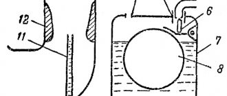
accelerator without a spray. Unscrew the sprayer, remove the discharge valve and press the accelerator bar. Be careful not to bend too low - the jet of gasoline can hit you high and hit you in the face. If no fuel comes out of the vertical channel, it means that the system of supply channels from the piston is clogged. If fuel flows here, then clean the nozzle itself. If the sprayer is clean, but there is no flow through it, check whether the discharge chamber under the piston is filled. Remove the piston and look into the chamber. It should be full of gasoline. If it is not there, check the channels for supplying gasoline from the float chamber to the ball under the piston and the mobility of the ball itself. When you press the piston from the supply channel, there should not be a breakthrough of a jet of gasoline in the opposite direction (the ball valve is leaking). Be sure to check for the presence of the discharge valve (brass needle) under the nozzle block, it is easy to lose. Subsequently, the feed can be quantified. To do this, the carburetor assembly will need to be placed above the container and ten times in a row, holding for a few seconds after pressing and after releasing, turn the throttle drive lever to full travel. For ten full strokes, the accelerator pump must supply at least 12 cm3 of gasoline. Setting the fuel level. Take the carburetor cover, insert a needle with a working sealing washer on it into the valve body of the float mechanism, place the float and insert its axis (Fig. 8). Holding the cap upside down as shown in the figure, measure the distance from the edge of the float to the plane of the cap. Distance A should be 40 mm. The adjustment is made by bending the tongue 4, which rests against the end of the needle 5. At the same time, make sure that the tongue always remains perpendicular to the axis of the valve, and there are no nicks or dents on it! At the same time, by bending the limiter 2, the gap B between the end of the needle 5 and the tongue 4 should be set within 1.2. 1.5 mm. On carburetors with a plastic float, clearance B is not adjustable. Having set the position of the float in this way, we, unfortunately, cannot guarantee complete tightness of the valve assembly. Try placing the lid vertically, with the float hanging down, and put a thin rubber hose with marked ends on the fuel supply fitting. Having such a hose is very convenient; you just need to mark the ends so that one always remains clean. Create excess pressure on the valve with your mouth and slowly turn the cap so that the float changes its position relative to it. The position at which air leakage stops should correspond to the distance between the float and the body, approximately equal to dimension A.
Now create a vacuum in the hose and evaluate the leak. If the valve is sealed, then
the vacuum remains unchanged for a long time. If there are leaks of any kind, the vacuum you create quickly disappears. If there is no tightness, then the sealing washer must be replaced. In some cases, the threaded fit of the valve body itself may be leaky. Try turning it up. Remember that the entire operation of the carburetor largely depends on the operation of the valve mechanism.
Carburetor assembly
. First of all, put in place all the jets that you
unscrewed in the carburetor body. Screw them securely, but without excessive force, so as not to damage the slot and make it easier to unscrew in the future. Place the spring and bar with the accelerator piston and economizer rod. Place the gasket on the housing connector plane. The carburetor cover, pre-assembled, is installed on top and should fit easily into place and be centered. Finally tighten the seven screws securing the cover. Try how the accelerator pump drive lever turns after assembly. It should move easily and still move the accelerator pump. If the lever does not move, it means that it was jammed in the wrong position during assembly. Remove the lid and start over.
Align the slot on the throttle drive lever with the tab on the accelerator drive rod. IN
In a certain position, they will coincide, and the rod will be inserted into the lever. Insert the upper end of the rod into the hole and secure with a cotter pin. Don't forget which of the two possible holes in the lever the rod was in before disassembly! By turning the throttle drive lever, now check whether the accelerator pump piston moves smoothly. For convenience, you can even remove the upper small