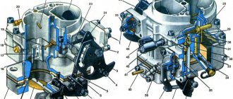
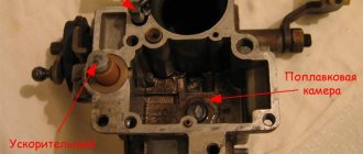
The main parts and components of a simple carburetor are: float chamber 7 with float 8 and shut-off needle 6, mixing chamber 1, diffuser 12, sprayer 11, jet 9 and throttle valve 2.
The required level of gasoline in the float chamber 7 while the engine is running is automatically maintained using the float 8 and the shut-off needle 6. When the gasoline level is low, the float drops and the needle 6 drops with it. The inlet opens and gasoline enters the float chamber. When the gasoline in the float chamber reaches a certain level, the float and with it the needle will rise so much that the needle closes the inlet and the flow of gasoline into the float chamber will stop.
Rice. Diagram of a simple carburetor: 1 - mixing chamber; 2 — throttle valve; 3 - hole connecting the float chamber with the atmosphere; 4 — needle valve seat; 5 — input channel; 6 - locking needle; 7 - float chamber; 8 — float; 9 — jet; 10 — air pipe; 11 - sprayer; 12 — diffuser
The float chamber is connected through a nozzle 9 to a spray nozzle 11. The nozzle has a calibrated hole through which a strictly defined amount of gasoline can flow per unit time.
Sprayer 11 is a tube with a hole for the outlet of gasoline. The gasoline in the sprayer and the float chamber is at the same level when the engine is not running. The gasoline level in the carburetor is adjusted so that it is below the upper end of the nozzle.
The float chamber is connected to the atmosphere through hole 3. If the engine is not running, then there will also be atmospheric pressure in the diffuser 12 and gasoline will not flow out of the atomizer.
Using the throttle valve, the amount of combustible mixture entering the engine cylinders is changed: the more the throttle valve is open, the more mixture enters the cylinders. The throttle valve is usually controlled using a foot pedal, as well as a button located on the instrument panel.
The carburetor is connected to the intake manifold with its mixing chamber 1.
The process of formation of a flammable mixture in the carburetor occurs as follows. During the intake stroke, the piston in the cylinder moves to bottom dead center and draws air through the intake manifold and carburetor. The flow area of the diffuser 12 is smaller than the sections of the air pipe 10 and the mixing chamber 1, so the air passes through the diffuser at high speed.
As a result, in the zone of greatest narrowing of the diffuser, where the atomizer is located, thinner gasoline is created and begins to flow out of the atomizer. Gasoline flowing from the atomizer is captured by the air flow and passes with it into the mixing chamber. In this case, gasoline is sprayed into tiny droplets, partially evaporates and mixes with air.
The evaporation of gasoline and its mixing with air continues in the intake manifold and in the engine cylinders.
A car engine usually operates in variable mode, since the power and speed of its crankshaft must change depending on the driving conditions of the car. In accordance with this, the quantity and composition of the combustible mixture supplied to the cylinders must be changed.
When starting a cold engine, the carburetor must prepare a rich combustible mixture, since gasoline in this case evaporates poorly and to ensure starting it is necessary to increase the supply of gasoline.
When operating at medium loads, the engine must operate most economically, for which the carburetor must prepare a lean mixture; a slight drop in power in this case does not affect the vehicle's driving mode.
The greatest engine power can be obtained if a large amount of rich mixture is supplied to the cylinders. Therefore, when the throttle valve is fully opened, the carburetor must prepare a rich mixture. An enriched mixture is also necessary for a sharp increase in engine crankshaft speed, since it burns in the cylinder faster than a normal combustible mixture.
The simplest carburetor discussed above does not provide the necessary change in the composition of the combustible mixture depending on changes in engine operating mode.
In the simplest carburetor, at low throttle opening, a small amount of air passes through it; the speed of air movement through the diffuser is so low that the vacuum in the diffuser is insufficient for the required amount of gasoline to flow from the atomizer, and the mixture turns out to be lean.
When switching from low engine idle speed to medium load mode with increasing vacuum in the diffuser, gasoline consumption increases to a greater extent than air consumption, and the combustible mixture becomes excessively rich.
As the throttle valve opens further, gasoline consumption changes in proportion to air consumption, the composition of the mixture remains constant, and the simplest carburetor does not provide the necessary enrichment of the combustible mixture when the throttle valve is fully opened.
To ensure the required composition of the combustible mixture at various engine operating modes, modern carburetors have additional devices:
- main dosing system
- idle system
- economizer
- accelerator pump
- starting device
Main dosing system
The main metering system ensures a gradual depletion of the combustible mixture as the vacuum in the diffuser increases, as a result of which, at medium loads, the engine operates on an economical combustible mixture.
Rice. Diagram of a carburetor with a compensation jet: 1 - throttle valve; 2 - calibrated hole; 3 — compensation jet sprayer; 4 - compensation jet; 5 - compensation well; 6 - main jet; 7 — main jet sprayer; 8 — diffuser
Modern carburetors use metering systems with a compensation jet, emulsifying gasoline in a spray nozzle, and regulating the vacuum in the diffuser. In a carburetor with a compensation jet, the required composition of the combustible mixture is obtained using two jets: main 6 and compensation 4.
In such a carburetor, changes in the composition of the combustible mixture depending on the engine operating mode are carried out by a compensation jet system.
Sprayer 3 communicates with an additional, i.e. compensation, well 5, into which gasoline enters through compensation nozzle 4.
The compensation well communicates with the atmosphere, and therefore an almost constant amount of gasoline enters the well through the compensation jet, depending on the difference in levels in the well and the float chamber.
When the engine is running, with increasing throttle opening, the gasoline consumption through the main jet increases, and the gasoline consumption through the compensation jet remains almost unchanged. The total amount of gasoline flowing from both nozzles increases to a lesser extent than the air flow, and the combustible mixture becomes leaner.
The depletion of the combustible mixture is also facilitated by the influx of air sucked in through the compensation well and passing along with gasoline through the atomizer.
The flow sections of the main and compensation jets are selected to ensure an economical composition of the combustible mixture when the engine operates at medium loads.
The diagram of a dosing system with gasoline emulsion in a sprayer is shown in the figure.
Gasoline from the float chamber through the main jet 8 enters the well 4. The well communicates with the atmosphere through the air jet 3 and the emulsion tube 5 with several holes in the lower part.
When gasoline leaves the well through sprayer 2, a vacuum occurs in the well. As a result, gasoline begins to flow into the well through the main jet 8 and air through the nozzle 3. Gasoline and air are mixed in the well and exit through the sprayer in the form of an emulsion. As the vacuum in the diffuser increases, the consumption of gasoline from the well increases to a greater extent than its influx through nozzle 8. The level of gasoline in the well decreases, the number of open holes in the emulsion tube and the amount of air entering the well increase.
As a result, gasoline consumption with increasing vacuum in the diffuser increases more slowly than in a simple carburetor, and the combustible mixture becomes leaner.
The sections of the main and air jets are selected such that the composition of the combustible mixture when the engine is operating at medium loads is economical.
The diagram of a carburetor, in which the required composition of the combustible mixture is provided by a dosing system with automatic control of the vacuum in the diffuser, is shown in the figure.
Rice. Scheme of a dosing system with emulsification of gasoline in a sprayer: 1 - air to tubes; 2 - sprayer; 3 — air jet; 4 - well; 5 - emulsion tube; o - air holes; 7 - float chamber; 8 — main jet; 9 — throttle valve; 10 - diffuser
This type of carburetor has two or three diffusers, two jets and two nozzles. Four elastic plates 4 are attached to the bottom of the large diffuser 1, which with their lower ends are pressed against the middle diffuser 3 and close the passage between the large and middle diffusers. In the neck of the small diffuser 2 there is a sprayer 7 of the main jet 5. The main amount of gasoline passes through the main jet. In the neck of the large diffuser 1 there is an atomizer 8 of an additional jet 6.
The amount of gasoline supplied through the nozzles depends on the vacuum in the diffusers.
The composition of the combustible mixture is controlled by the main jet 5 due to the fact that the vacuum in the small diffuser does not change in proportion to the total air flow.
When the throttle is opened slightly and a small amount of air passes through the carburetor, all air flow is directed through the small and medium diffusers. In a small diffuser, a vacuum is created such that an amount of gasoline sufficient to obtain an enriched mixture emerges from the main jet atomizer.
Rice. Diagram of a carburetor with automatic control of vacuum in the diffuser: 1 - large diffuser; 2 — small diffuser; 3 — middle diffuser; 4 - elastic plate; 5 - main jet; 6 — additional jet; 7 — main jet nozzle; 8 — additional jet sprayer
As the throttle opening increases or the engine speed increases, the amount of air passing through the carburetor increases.
Under the influence of air pressure, the plates 4 bend and part of the air passes past the small diffuser. The greater the air flow, the more the plates move apart and the more air passes past the small diffuser. As a result, the vacuum in the small diffuser does not increase in proportion to the increase in air flow; Gasoline flow through the main jet decreases compared to the total air flow, and the combustible mixture becomes leaner.
With the correct selection of both jets, in almost all engine operating modes you can obtain a combustible mixture of the desired composition.
How to choose a new carburetor?
Although carburetors are reliable devices, they require a complete replacement rather than a major overhaul. Often the carburetor is replaced when all channels are severely coked, connections are deformed or other mechanical damage occurs.
The good news is that the carburetor does not need to be replaced with exactly the same one. You can choose a more economical or powerful option. There are quite a lot of options on the market.
When choosing a carburetor, consider the following characteristics:
- Main fuel jet. Find out from a knowledgeable specialist what type of jet the jet should be and what capacity it should be. The same applies to the air jet.
- Throttle diameter. It depends directly on the power of the internal combustion engine cylinders.
- Diffuser. It is recommended to choose a carburetor in which the diameter of the diffusers is no more than 0.8 of the diameter of the mixing chamber.
- The accelerator pump must match the car model.
The most reliable carburetor manufacturers:
- American Walbro and Motorcraft.
- Czech AT.
- German
- Polish Weber.
- Russian-French Solex.
Solex carburetor
There are not very well-known carburetor manufacturers on sale, which are made in Indonesia, Thailand, and China. Of course, they are of worse quality, but they are no less reliable and cost less. The approximate price for carburetors starts from 5,000 rubles.
Video: Carburetor design (Especially for AUTObabies)
A carburetor is a simple device that is currently practically not installed in modern cars. Most often they can be found on our VAZ cars, which are sold on the secondary market.
Although these fuel systems have been replaced by injection systems, they remain a symbol of reliability and have a simple operating principle, control and adjustment.
And injection designs, compared to carburetors, are more environmentally friendly, have high efficiency, and operate without problems in any weather conditions.
The main parts of a standard carburetor are: the mixing and float chamber, the float and locking needle, the throttle and air dampers, the diffuser, the accelerator pump, the main metering system and the sprayer. The prepared combustible mixture of air and gasoline emulsion is supplied directly to the cylinders of the internal combustion engine, ensuring its power and reliable operation.
At the moment, carburetors are still installed in motorcycles, lawn mowers and other gas-powered tools. Is it worth buying a car with a carburetor? If you look at the operating diagram of such a car, the carburetor, with timely maintenance, can work for a long time than other mechanisms.
Repost and the information will always be at hand ✅
Idle system
When the engine is idling, in order to save fuel and reduce wear on engine parts, they strive to keep the crankshaft speed to a minimum. At idle, the engine operates with the throttle valve almost completely closed. In this case, the air flow is small, and the vacuum in the diffuser is not enough to supply air; the required amount of gasoline from the main dosing system.
The required composition of the combustible mixture for this engine operating mode is provided by the idle system. Gasoline flows through jet 2 into emulsion channel 7, located in the carburetor body. Air enters the same channel through jet 1. Air and gasoline are mixed and come out of hole 9 in the form of an emulsion.
In modern carburetors, in order to smoothly transition from idle speed to medium speed, there are two holes 8 and 9 for the exit of the emulsion. Hole 8 is located in front of the throttle valve, and the other hole 9 is behind it. When the throttle valve is closed, the emulsion exits through hole 9, and through hole 8 air is additionally sucked into the emulsion channel 7.
When the throttle valve is smoothly opened, a vacuum is also created near hole 8 and the emulsion begins to emerge from it, which ensures the required quantity and proper composition of the combustible mixture.
As the throttle valve opens, airflow increases; Accordingly, the vacuum in the diffuser and the flow of gasoline from the main jet increase. The carburetor switches from the idle system to the main metering system.
Rice. Idle system: 1 - air jet; 2 — idle jet; 3 - main jet; 4 — idle speed adjustment screw; 5 — lever on the throttle axis; 6 — screw for adjusting the composition of the combustible mixture; 7 — emulsion channel; 8 and 9 - holes for emulsion outlet; 10 - throttle valve
The amount of emulsion supplied by the idle system is regulated by screw 6, with the help of which the flow area of hole 9 is changed. When the screw is screwed in, the amount of emulsion decreases, and when turned out, it increases.
The engine crankshaft speed at idle is adjusted by changing the opening value of the throttle valve 10 using screw 4.
What is a carburetor and what is it for?
In order for an internal combustion engine to operate optimally, it is necessary to mix fuel and air in a certain proportion and feed this mixture into the combustion chamber. The mixture parameters can change depending on the operating mode of the internal combustion engine, fuel consumption too, which means you need a device that will do all this automatically.
A carburetor is a device for mixing air with fuel. As a result of its operation, at the right moment, atomized gasoline mixed with air enters the combustion chamber of the engine, ready for ignition. Despite the fact that there is only one carburetor for several cylinders, the mixture always gets to the right place through the intake manifold thanks to the coordinated operation of all internal combustion engine elements.
Economizer
The main metering system of the carburetor is adjusted so that at medium loads the engine runs on an economical mixture. At maximum load conditions, an enriched mixture must be supplied to the engine cylinders. Enrichment of the mixture is provided by an additional carburetor device - an economizer.
The economizer valve 7 is pressed against the seat by a spring 9 and opens under the pressure of a rod 5, which has a piston 3 at the upper end. The piston is placed in a cylinder 4, the lower cavity of which is connected to the air pipe, and the upper cavity is connected to channel 8 with a mixing chamber behind the throttle valve.
The piston with the rod, under the action of spring 2, tends to occupy the lower position. When the throttle valve is opened slightly, a large vacuum is created behind it, which is transmitted through channel 8 to the upper cavity of the economizer cylinder. Under the influence of vacuum, the piston compresses spring 2 and takes the upper position. Valve 7 closes the inlet.
With an increase in the opening of the throttle valve, the vacuum in the air pipe decreases so much that under the action of spring 2, piston 3 will go down, rod 5 will press on valve 7, which will open the inlet hole, and an additional amount of gasoline will begin to flow from the float chamber through nozzle 10 into sprayer 1 - the mixture enriches itself.
The role of the throttle valve in the operation of the carburetor
The amount of fuel mixture that enters the cylinders depends on the position of the throttle valve, which, in turn, is connected to the gas pedal.
In addition, in the interior of some carburetor cars there is a special lever on the dashboard that can also be used to control the throttle. It is commonly referred to as a "choke", although technically it is a "cold start device". By pulling its handle towards himself, the driver closes the air damper, limiting the access of air and increasing the vacuum in the carburetor mixing chamber. As a result, gasoline is sucked out of the float chamber more intensively and, with a lack of air, prepares an enriched combustible mixture for the engine, which is necessary to start a cold engine.
In order for the engine to idle, the carburetor has special additional calibrated air jets, through which a strictly defined amount of air enters under the throttle valve and mixes with the fuel, even if you take your foot off the gas pedal.
Acceleration pump
The accelerator pump is designed to briefly enrich the combustible mixture when the throttle valve is opened sharply.
Rice. Diagram of an economizer with a pneumatic drive: 1 - sprayer; 2 - spring; 3 - piston; 4 - cylinder; 5 - rod; 6 - main jet; 7 — economizer valve; 8 - channel; 9 — valve spring; 10 — economizer jet
In the carburetor body there is a cylinder 8 in which the piston 7 of the pump is placed. The cylinder is connected to the float chamber by a channel, at the beginning of which there is a check valve 9. The outlet channel has a needle valve 10.
The piston is driven by the throttle valve drive mechanism through lever 13, driver 12, rod 11 and pressure plate 4, which acts on the piston through spring 5. When the throttle valve is smoothly opened, the pump piston slowly lowers and gradually squeezes gasoline from the cylinder into the float chamber through the open check valve 9.
When the throttle valve is opened sharply, the piston quickly lowers and squeezes gasoline out of the cylinder. In this case, gasoline lifts the check valve, which closes the inlet, preventing gasoline from escaping back into the float chamber. Gasoline, lifting the needle valve 10, is injected through the nozzle 3 into the carburetor mixing chamber and enriches the combustible mixture.
Carburetors. The operating principle of a simple carburetor
Carburetors. The operating principle of a simple carburetor
The process of preparing a combustible mixture of fuel and air outside the engine cylinder is called carburetion. The device that carries out this process is called a carburetor.
Carburetors can be of three types: evaporative, injection and float suction. Evaporative carburetors are designed to operate on easily evaporating fuel. Air passing over the surface of the fuel is saturated with its vapors and forms a combustible mixture.
An injection (or membrane) carburetor has a rather complex design consisting of two high and low pressure fuel chambers, separated by a first membrane, respectively, as well as two air chambers - high and low pressure, separated by a second membrane. Under the influence of the pressure difference, the elastic membrane bends and fuel enters the fuel chamber through the gas pump.
The most widely used are float suction carburetors with fuel suction at a vacuum that occurs in the narrowed part of the carburetor air channel - the diffuser due to a local increase in air flow speed.
In the body of a simple carburetor there is a float chamber 6 and a mixing chamber 1. Float 8, acting on the needle valve 7, maintains a constant fuel level in the float chamber. Hole 5 communicates the float chamber with the atmosphere.
Rice. Diagram of the design and operation of a simple carburetor
1 – mixing chamber, 2 – diffuser, 3 – air pipe, 4 – sprayer, 5 – air hole of the float chamber, 6 – float chamber, 7 – needle valve, 8 – float, 9 – jet, 10 – throttle, 11 – inlet engine pipeline. , 12 – throttle lever.
In the upper part of the mixing chamber there is an inlet air pipe 3, in the middle there is a diffuser 2 having a narrowed flow area (neck), and in the lower part (outlet pipe) there is a damper 10, called a throttle, mounted on a roller passed through holes in the walls of the mixing chamber. Using lever 12 at the outer end of the throttle shaft, the throttle can be turned to the required position. The outlet pipe of the mixing chamber is connected to the inlet pipe 11 of the engine via a flange.
Starting device
The most common device for enriching the combustible mixture when starting the engine is the air damper 12 installed in the carburetor air pipe.
When starting the engine, open the throttle valve slightly and close the choke valve. As a result, when cranking the engine crankshaft, a strong vacuum is created in the carburetor and gasoline flows out of all jets - the combustible mixture becomes richer.
The air damper has a safety valve 11, which opens automatically as soon as the engine starts running.
The air damper is controlled using a button located on the instrument panel and connected to the damper by a flexible rod.
Rice. Diagram of an accelerator pump with a mechanical drive: 1 - air pipe; 2 - air channel; 3 — accelerator pump nozzle; 4 - pressure plate; 5 - spring; 6 - rod; 7 - piston; 8 - cylinder; 9 - check valve; 10 — needle valve; 11 - thrust; 12 - leash; 13 - lever
As the engine warms up, the choke valve is gradually opened. Operation of the engine with the air damper closed should be as short as possible, since a strong enrichment of the combustible mixture during operation of a cold engine causes increased wear.
Maximum speed limiter
Operating the engine at crankshaft speeds above the maximum permissible limits leads to excessive fuel consumption and increased wear of engine rubbing parts. To avoid this, car engines are often equipped with pneumatic speed limiters.
Throttle valve 4 has a shaped shape with a beveled plane of the left half, and its axis is shifted by 1.5-2 mm relative to the axis of the mixing chamber.
A spring 9 is attached to the damper, which tends to hold the damper in the open position.
When the engine is running, the air flow acts on the throttle valve and, since the upper plane of its left half is beveled and the axis is shifted to the right, it tends to close the valve.
When the number of revolutions of the crankshaft becomes higher than the permissible speed, the pressure of the air flow on the left side of the damper increases so much that the damper, overcoming the resistance of the spring, closes, a smaller amount of combustible mixture is supplied to the cylinders and the engine crankshaft speed decreases.
Rice. Engine crankshaft maximum speed limiter: 1 - foot; 2 - nut; 3 - fitting; 4 — throttle valve; 5 - rod; 6 — needle bearing; 7 — throttle axis; 8 — earring; 9 - spring; 10 - gasket; 11 — cap; 12 — hairpin
The speed limiter operates independently of the throttle pedal. When the pedal is released, the throttle valve is closed under the action of the pedal return spring, which is much stronger than the speed limiter spring.
When you press the pedal, the throttle valve is released from the action of the pedal return spring and opens due to the tension of its spring.
By changing the tension of spring 9 by rotating the adjusting nut 2, you can adjust the maximum number of revolutions of the engine shaft.
Let's consider the design and operation of carburetors installed on the engines of some domestic cars.
History of carburetors
The first carburetor was created in 1895. The founder of the idea, as well as the assembler and tester of the carburetor, is considered to be the German Wilhelm Maybach. It is noteworthy that he did not study anywhere, but is a self-taught technician.
Since then, carburetor engines have undergone significant changes, but the essence of their operation remains the same. The main difference between modern carburetors and the first models is the method of forming the air-fuel mixture - in old models, gasoline simply evaporated, but now fuel is atomized in the air.
In 1925, the German company Bosch was the first in the world to launch mass production of carburetor engines. They are already equipped with a high-pressure fuel pump and a gasoline injection system through the use of injectors. Thanks to the new principle of equipping vehicles, it was possible to stabilize the operation of the machines and make them safer.
The introduction of fuel injection pumps and nozzle injection systems into power units provided the impetus for the development of a new type of engine that could consume diesel fuel . Already in 1935, the first passenger car with a diesel power unit rolled off the assembly line.
After the release of diesel cars, it was possible to develop new types of carburetors that increased the power of gasoline engines. These new models were equipped with an intake manifold. Further developments in the field of adding power characteristics to carburetors made it possible to create an engine with direct fuel injection, which had high torque. Cars with this type of carburetor began to be produced en masse in the mid-1940s.
In 1965, Bosch again conquered the global auto industry by designing new carburetors with a distributed injection system. This system reduced the cost of the entire structure, since instead of a massive and expensive fuel injection pump, a conventional electric pump could be used.
In 1994, another company, Mitsubishi Motors, began introducing a direct injection system into the production of carburetor cars. New power units significantly reduce the amount of fuel consumed, and with the same volume of combustion chambers, such engines provide maximum torque. Direct injection carburetors produce fewer fumes into the environment.
Today, various manufacturers use carburetors with both direct and distributed injection. However, the development of carburetor power units continues.
Carburetor K-22D
Carburetor K-22D , installed on the engine of the GAZ-69 car, is a three-diffuser carburetor.
The main dosing system of the carburetor operates on the principle of regulating the vacuum in the diffuser. It consists of a main jet 27, the nozzle of which goes into the small diffuser 10, an additional nozzle 25, the nozzle of which goes into the neck of the large diffuser 14, and an automatic bypass air valve, consisting of four elastic plates 5.
The amount of gasoline passing through the main jet can be adjusted depending on the operating conditions of the engine using needle valve 26.
Rice. Carburetor K-22D: 1 - flange; 2 — screw for adjusting the idle mixture quality; 3 - hole for the emulsion to escape during the transition from idle speed to medium speed of the engine crankshaft; 4 - hole for vacuum regulator; 5 - elastic plate; 6 — idle jet; 7 — middle diffuser; 8 — emulsion idle jet; 9 — idle air jets; 10 — small diffuser; 11 — air damper safety valve; 12 — air damper; 13 - tube; 14 - large diffuser; 15 — accelerator pump nozzle; 16 — sprayers; 17 — discharge valve of the accelerator pump; 18— accelerator pump piston; 19 — check valve; 20 - float; 21 - locking needle; 22 — float chamber body; 23 — accelerator pump piston drive rod; 24 — economizer valve; 25 — additional jet; 26 — needle valve of the main jet; 27 - main jet; 28 — economizer jet; 29 - throttle valve
The idle system consists of an idle jet 6, two air jets 9 and an emulsion jet 5.
The economizer and accelerator pump are combined into one system, consisting of an accelerator pump with a piston 18, a pump discharge valve 17, a jet 15, a check valve 19, a jet 28 and an economizer valve 24. The accelerator pump is driven mechanically by the throttle valve.
The float chamber communicates through tube 18 with the air pipe, and not with the atmosphere, as a result of which the influence of the air filter resistance on the operation of the carburetor is eliminated.
When the engine is running at low idle speed, the throttle valve is closed. Due to the high speed of air movement through the narrow gap between the damper and the walls of the mixing chamber, a vacuum is formed in the throttle valve area.
Since the outlet of the idle system is located in this area, the vacuum is transferred to the system and it operates as an independent carburetor.
Gasoline from the float chamber enters the idle jet 6 through an additional jet 25 through the carburetor channels. Having passed the idle jet, the gasoline rises and, meeting the air entering through the air jet 9, mixes with it and passes through the emulsion jet 8 in the form of an emulsion.
Coming out of the emulsion nozzle, gasoline again meets the air flow passing through the air nozzle and is mixed with it. The emulsion exits through the idle hole behind the throttle valve.
The emulsion consumption and, consequently, the quality of the combustible mixture at idle is adjusted by screw 2.
When the engine is running and at medium loads (the throttle valve is open approximately halfway), the vacuum in the diffusers increases so much that the bulk of gasoline comes out of the nozzles of the main 27 and additional 25 nozzles.
As the air flow passing through the diffuser increases, the plates 5 of the air bypass valve diverge and the air flow passes by the small 10 and medium 7 diffusers, automatically adjusting the vacuum in the small diffuser and, consequently, the composition of the combustible mixture depending on the throttle opening value.
When the engine is running at full load, the throttle valve is fully open. In this case, the piston 18 of the accelerator pump is in the lower position and, pressing the economizer valve 24, opens access to an additional amount of gasoline, which from the float chamber passes through the economizer nozzle 28 to the additional nozzle atomizer.
When the throttle valve is opened sharply, the accelerator pump piston drops sharply and squeezes gasoline out of the cylinder. Check valve 19 closes, and valve 17 of the accelerator pump opens, and gasoline is released in a stream through jet 15 into the neck of large diffuser 14 - the combustible mixture is enriched.
When starting the engine, the combustible mixture is enriched by closing the air damper 12, which has a safety valve 11.
The K-22G carburetor, which is installed on the engines of GAZ-63 and GAZ-51 A cars, is also made according to the design of the K-22D carburetor.
The structure of the carburetor today
Today, float models are used, which are the most advanced. They can be seen on most cars.
A float carburetor consists of many elements:
- Float chamber to maintain fuel at a given level.
- A float equipped with a special needle, which is used to dose the level of gasoline.
- Mixing chamber - for mixing finely dispersed fuel with air.
- A diffuser is a narrowed area to increase air speed.
- A sprayer equipped with a nozzle that connects the chambers delivers the mixture to the diffuser.
- Throttle valve - to regulate the flow of working fluid.
- Air damper - to regulate the flow of air entering the carburetor. Using the element, a “rich”, “normal” or “poor” mixture is created.
- Idle system - supplies fuel past the mixing chamber through special channels into the throttle space.
- Econostats and economizers provide additional fuel supply under significant loads. Econostats operate from air rarefaction, economizers are controlled forcibly.
- Fuel suction - for forced enrichment of the fuel mixture. Using the lever, the driver opens the throttle slightly, air passes through the mixing chamber and takes in more fuel. As a result, the mixture becomes richer, helping to start a cold engine.
Carburetor type K-82
Rice. Carburetor type K-82: 1 - flange; 2—emulsion channel; 3 - gasket; 4 — accelerator pump channel; 5 — accelerator pump valve; 6 — accelerator pump nozzle; 7 — small diffuser; 8 - annular slot; 9 — air pipe housing; 10 — air damper; 11 - safety valve; 12 — idle jet; 13 — economizer valve seat with pneumatic drive; 14 — economizer valve needle; 15 - hole through which the float chamber is connected to the air pipe; 16 — screw for adjusting the idle mixture quality; 17 — piston of the pneumatic drive of the economizer; 18 — pressure plate; 19 — economizer valve pusher with mechanical drive; 20 — accelerator pump piston rod; 21 - spring; 22 — filter plug; 23 - mesh filter; 24 - locking needle; 25 - gasket; 26 — float chamber body; 27 — float: 28 — accelerator pump piston; 29 - check valve; 30 — accelerator pump piston drive rod; 31 — rod driver; 32— economizer valve ball; 33 — accelerator pump drive lever; 34 — economizer valve spring; 35 — economizer valve seat; 36 - sealing ring; 37 — economizer piston spring; 38 — main jet; 39 - channel; 40 - plug; 41 — full power jet; 42 — throttle valve; 43 - emulsion tube; 44 — air jet; 45 - outlet
The K-82 type carburetor is a double-diffuser carburetor. It is installed on the engines of ZIL-164A and ZIL-164 cars.
The main metering device, operating on the principle of emulsifying fuel in a sprayer, consists of two fuel jets 38 and 41, an air jet 44 and a sprayer in the form of an annular slot 8 in a small diffuser. An emulsion tube 43 with holes is placed in the well of the main dosing device.
The idle system consists of an idle jet 12, channel 2 and an outlet 45 in the form of a slot. The quality of the combustible mixture at idle is regulated by screw 16, and its quantity by opening the throttle valve.
A piston-type accelerator pump with a mechanical drive from the throttle valve supplies fuel through channel 4 to nozzle 6.
The carburetor has two economizer valves. The mechanically actuated valve consists of a seat 35, a ball 32 and a spring 34, which presses the ball against the seat. A pneumatically actuated valve consists of a seat 13 and a needle 14, which is connected to a piston 17 of the pneumatic actuator. The piston, with the help of spring 37, occupies the upper position when the engine is not running. The space under the piston is connected by channel 39 to the mixing chamber behind the throttle valve.
When the engine is idling, the throttle valve is closed. The vacuum behind the throttle valve spreads through outlet 45 along channel 2 to idle jet 12. As a result, gasoline from the well of the main metering device flows to the idle jet. At the same time, air enters the nozzle. The mixture of gasoline and air, passing through the idle jet, enters the outlet.
Engine operation at medium speed. As the throttle valve opening increases, the air flow passing through the small diffuser increases, as a result of which the vacuum in the diffuser is sufficient for the main metering system to come into operation.
Gasoline from the float chamber flows through jets 38 and 41 into the well. Air also enters here through the nozzle 44 and holes in the emulsion tube 43. The mixture of gasoline and air exits through the annular slot 8 in the small diffuser.
The cross-sections of the fuel and air jets are selected so that a lean mixture is prepared at small and medium throttle openings. In these cases, both economizer valves are closed. The economizer valve with a mechanical drive is closed under the action of spring 34. The valve with a pneumatic drive is closed due to the vacuum in the cylinder under the piston 17. Under the influence of the vacuum transmitted from the mixing chamber, the piston occupies the lower position, compressing the spring 37. Together with the piston, it is in the lower position needle 14, which with its lower end is pressed against seat 13 and closes the fuel channel.
To prevent the vacuum from being transferred to the float chamber, piston 17 in this position sits on the sealing ring 36.
As the throttle valve opening increases, the vacuum under the piston of the pneumatic economizer decreases and the piston rises under the action of spring 37. When the vacuum behind the throttle valve decreases to a certain value (125 mm Hg), the piston and with it the needle 14 will rise so much that the needle opens the inlet hole of the nozzle and an additional amount of gasoline from the float chamber will begin to flow to the full power nozzle 41. The combustible mixture is slightly enriched, which is necessary during unsteady vehicle movement (for example, during acceleration, when the vehicle is moving on dirt roads and terrain).
The mechanically actuated economizer valve opens when the throttle valve is almost fully open.
When the throttle valve is opened, the rod 30 is lowered; when the valve is almost completely open, the plate 18 on the rod 30 presses on the pusher 19, which, when lowered, will open the ball valve. Benzene from the float chamber is additionally supplied to the full power jet 41, the cross-section of which is designed for preparing an enriched mixture.
When the throttle valve is opened sharply, the mixture is enriched by the accelerator pump. In this case, the piston drops sharply and gasoline is squeezed out from under the piston. Check valve 29 is pressed against the seat and closes the channel leading into the float chamber. Gasoline is supplied through channel 4 to jet 6 and flows out of it in a thin stream, enriching the combustible mixture. Enrichment of the combustible mixture when starting a cold engine is carried out by closing the air damper. The air and throttle valves are connected by drive rods so that when the air valve is completely closed, the throttle valve is slightly open. This enriches the mixture sufficiently and ensures reliable engine starting.
Advantages and disadvantages of carburetors
Only the deaf have never heard of the horrors of constant carburetor repair. But what really? What are the advantages of this device and is there any point in dealing with it at all? Strange as it may sound in our technological age, the carburetor has several serious advantages.
- Simplicity of design. No, the point is not that this is a very simple mechanism. But compared to the electronic components of today's cars, the carburetor is much easier to repair, maintain, and even operate. Most carburetors do not have any electronics, only mechanical devices, which means that a person with “straight hands” can repair and maintain it himself. The “old guard” – our parents, who are accustomed to delving into their “beloved” Zhiguli and Cossacks – remember this well.
- Maintainability. Anything that breaks in the carburetor can be repaired without “excess blood.” The necessary spare parts can be purchased (there are manufacturers that still produce repair kits. Why not?).
- When working with low-quality fuel, the carburetor turns out to be much more durable and stable than the injector. In general, it is not too demanding on cleanliness, and if it gets clogged, it can be easily cleaned at home (“garage”).
- A small amount of water entering the carburetor will not harm it, unlike the injector. However, over time it will require cleaning and calibration.
- And finally, the carburetor does not require connection to the electrical network, sensors, processor and other “joys” of civilization. It operates solely on the energy of the air sucked in by the engine, which means it was the best option for installation on older cars that had no electronics at all.
But there are also disadvantages due to which carburetor cars eventually disappeared from the world automotive arena.
- Technology required a fuel supply system with flexible adjustments, rather than with constant parameters, in order to minimize fuel consumption (which no one had previously taken into account). Therefore, the carburetor was replaced by an injection system, which is still being developed and improved.
- The second significant disadvantage is the dependence of the carburetor on weather conditions. During the cold season, condensation collects inside, interfering with operation; in winter, there is a risk of icing of the inside. At the same time, the summer heat also prevents it from working stably due to active evaporation - disruptions in the supply of the mixture begin.
- Well, the third drawback is that the environmental performance is significantly lower compared to an injector. In the modern struggle for the environment, carburetor cars simply do not stand up to criticism, since their harmful emissions are much higher.