Any car equipped with an internal combustion engine will necessarily have an ignition system in its electronics. In order for the mixture of atomized fuel and air in the cylinders to ignite, a decent discharge is needed. Depending on the modification of the car’s on-board network, this figure reaches 30 thousand volts.
Where does this energy come from if the battery in the car only produces 12 volts? The main element that generates this voltage is the ignition coil. Details about how it works and what modifications there are are described in a separate review .
Now we will focus on the principle of operation of one of the types of ignition systems - contact (different types of ignition systems are described here ).
Where is it used?
Past and present owners of VAZ “classics”, who understand the design of such cars, are well aware of the weak points and operating principles of the contact-type ignition circuit.
Its peculiarity lies in the distribution of voltage to the combustion chambers of the engine through contact connections (hence the name).
Modern cars are equipped with more modern (electronic) ignition, which is controlled by a microprocessor.
The main systems operating on the contact principle include:
- KS3 (KSZ) - the most common type of circuit, the structure of which contains a distributor, a coil and a breaker.
- KTS3 (HKZ-2, JFU4, HKZk) - ignition system with a contact sensor and preliminary energy storage.
- KTC3 (TSZi) is another type of system that operates on the contact principle. It contains a transistor and contacts, as well as an inductive energy storage device.
contact Group
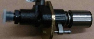
Let's look at a contact breaker. It has a cam on which there are four identical protrusions. And also a stand with contacts. With its help, the contact group opens. From time to time it is necessary to lubricate this cam by applying oil to the felt.
The ignition sensor-distributor is equipped with a stand to which an axle is secured with rivets. It has a textolite bushing on which a small lever is mounted. On the latter there is a movable contact, which is pressed by a spring to the stationary one. There is also a PCB block; it comes into contact with the protruding parts of the breaker.
General operating principle
The presence of a contact ignition system in a car means that the ignition of the fuel in the cylinders is carried out upon the appearance of a spark from the spark plug.
In this case, the spark itself occurs when a high voltage pulse arrives from the ignition coil.
The key function is performed by the ignition coil, which, according to its operating principle, resembles a transformer.
It consists of two windings (primary and secondary) wound on a metal core.
First, voltage is applied to the primary winding, after which a current is created in the coil.
As soon as a short-term break in the primary circuit occurs, the magnetic field is leveled, but a high voltage (about 25,000 Volts) appears in the secondary winding.
At this moment, a voltage of 300 Volts is also present on the primary winding.
The reason for its appearance is self-induction currents. It is because of the appearance of this current that the breaker contacts burn and spark.
From the above we can conclude that the secondary voltage directly depends on the following aspects:
- Magnetic field;
- The intensity level of the current drop in the primary winding.
To increase the secondary voltage and reduce the risk of burning the contact group, a capacitor is included in the circuit (installed in parallel). Even with a slight opening, the capacitor is charged.
A schematic diagram of the contact ignition system is shown below.
The capacitance discharge occurs through the primary winding, through the formation of a reverse voltage pulse current. Thanks to this feature, the magnetic field disappears and the secondary voltage increases.
The optimal capacitor capacity for a contact ignition system is 0.17-0.35 µF. For example, domestically produced Zhiguli cars have a capacitor with a capacitance of 0.2-0.25 μF (at a frequency of 50 to 1000 Hz).
If the vehicle's ignition system operates without failure, the secondary voltage should constantly increase. It depends on two main parameters - the size of the gap between the spark plug electrodes, as well as the pressure in the cylinders of the machine.
For a contact ignition system, this parameter (secondary voltage) should be at the level of 8-12 Volts.
In order for the system to operate without failures, at the moment of interruption the mentioned indicator increases to 16-25 kV. The presence of such a reserve allows you to avoid adverse consequences from certain fluctuations in the ignition system.
The problems mentioned above include adjustments to the composition of the combustible mixture or changes in the distance between the spark plug electrodes.
For example, a decrease in the oxygen level in the fuel-combustible mixture leads to an increase in voltage to 20 kV.
Despite a number of measures taken, the creators of the contact ignition system were unable to completely avoid burning the contact group. The optimal way to reduce this effect is to strictly maintain the gap at a minimum level (0.3-0.4 mm).
As an example, we can cite domestic VAZ cars, in which the gap in the breaker is 0.35-0.45 mm, which corresponds to an angle of 52-58 degrees (provided that the contact group is in a closed state).
If this angle changes, the voltage in the secondary winding is also adjusted. As a result, sparks appear not only on the contacts, but also on the sliders. For this reason, the quality of the spark decreases and the engine loses power.
The reliability of the contact ignition system, which depends on a number of factors, deserves special attention:
- Shape, energy and time of spark appearance;
- The number of sparks in a certain area;
- Secondary voltage (one of the most important characteristics). The larger this parameter, the less dependent the system is on the composition of the combustible mixture and the level of cleanliness of the electrodes.
Operating procedure for an inline 4 cylinder engine
The operating order of a 4-cylinder engine is designated as X―X―X―X where X is the cylinder numbers. This designation shows the sequence of alternating cycle strokes in the cylinders.
The order of operation of the cylinders depends on the angles between the crankshaft cranks, on the design of the gas distribution mechanism, and the ignition system of the gasoline power unit. In a diesel engine, the fuel injection pump takes the place of the ignition system in this sequence.
Of course, you don’t need to know this to drive a car.
It is necessary to know the operating order of the cylinders when adjusting valve clearances, changing the timing belt or setting the ignition. And when replacing high voltage wires, the concept of the order of operating cycles will not be superfluous.
Duty cycle
Depending on the number of strokes that make up the operating cycle, internal combustion engines are divided into two-stroke and four-stroke. Two-stroke engines are not used in modern cars; they are used only on motorcycles and as starters for tractor power units. The cycle of a four-stroke gasoline internal combustion engine includes the following strokes:
- Intake - the exhaust valve is closed, the intake valve is open, the piston moves downward, and the air-fuel mixture is sucked in.
- Compression - all valves are closed and the piston moves upward, compressing the air-fuel mixture.
- Working stroke - the valves remain closed; at the end of the previous stroke, a spark ignites the compressed mixture. The piston, under the influence of gas pressure from the burnt mixture, goes down, rotating the crankshaft.
- Exhaust - at the end of the previous stroke, the exhaust valve opens. The piston, pushed by the crankshaft, moves upward and displaces combustion products into the exhaust manifold.
The diesel cycle is different in that during intake only air is sucked in. Fuel is injected under pressure after air compression, and ignition occurs from contact of the diesel engine with air heated by compression.
Numbering
The cylinder numbering of an in-line engine starts with the one furthest from the gearbox. In other words, from the timing belt or chain side.
Sequence of work
On the crankshaft of an in-line 4-cylinder internal combustion engine, the cranks of the first and last cylinder are located at an angle of 180° to each other. And at an angle of 90° to the cranks of the middle cylinders. Therefore, to ensure the optimal angle of application of driving forces to the cranks of such a crankshaft, the order of operation of the cylinders is 1-3-4-2, as in VAZ and Moskvich internal combustion engines, or 1-2-4-3, as in GAZ engines.
Alternation of measures 1-3-4-2
It is impossible to guess the order of operation of the engine cylinders by external signs. You should read about this in the manufacturer's manuals. The easiest way to find out the operating order of the engine cylinders is in the repair manual for your car.
crank mechanism
- The flywheel maintains the inertia of the crankshaft to move the pistons from the upper or lower extreme positions, as well as to rotate it more evenly.
- The crankshaft converts the linear movement of the pistons into rotation and transmits it through the clutch mechanism to the gearbox input shaft.
- The connecting rod transmits the force applied by the piston to the crankshaft.
- The piston pin creates a hinge connection between the connecting rod and the piston. Manufactured from alloyed high carbon steel with surface hardening. Essentially it is a thick-walled tube with a polished outer surface. There are two types: floating or fixed. The floaters move freely in the piston bosses and in the bushing pressed into the connecting rod head. The finger does not fall out of this design thanks to the locking rings installed in the grooves of the bosses. The fixed ones are held in the connecting rod head due to a shrink fit, and rotate freely in the bosses.
https://youtube.com/watch?v=ilZyCD-QlJg
Device
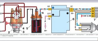
It is no secret that the contact ignition system consists of many different elements:
- battery;
- Mechanical breaker and distributor. The first gives a low voltage current, and the second - a high voltage;
- Lock, coil and spark plugs;
- There are two types of ignition timing regulators - centrifugal and vacuum;
- High voltage wires.
Let's look at the main elements in detail:
- A breaker is a unit that provides short-term separation of the current chain in the low voltage winding. At the moment of rupture, a high voltage is formed in the secondary circuit.
- Capacitor - a part whose purpose is to prevent burning of contacts in the breaker circuit. The container is installed parallel to the contact group, which allows the product to absorb a larger amount of energy. An additional function of the capacitor is to increase the voltage on the secondary winding.
- Distributor - an element of the contact ignition system, which ensures the distribution of voltage potential to each of the cylinder spark plugs. Structurally, the device consists of a cover and a rotor. There are contacts in the upper part, and the potential from the coil is directed to the central contact, and through the side contacts to the spark plugs.
- Ignition coil - a device that converts voltage (from low to high). The part is located in the engine compartment, as are most of the elements of the contact ignition system. Structurally, the product has two windings. One is low voltage and the other is high voltage.
- Distributor - is a device in which a breaker and a distributor are located together, operating from the engine crankshaft.
- Centrifugal regulator is a unit that provides a change in the ignition timing. This parameter represents the crankshaft rotation angle at which voltage is applied to the spark plugs. To ensure complete combustion of the combustible mixture, the angle in question is set ahead of time.
Structurally, the regulator is a pair of weights that act on a plate with breaker cams placed on it. It is worth noting here that the plate moves freely, but the advance angle is set due to the position of the motor distributor.
- Vacuum type regulator - a device that provides a change in the advance angle against the background of adjusting the level of load on the engine (changes when you press the gas pedal). The regulator is combined with the cavity of the throttle assembly and adjusts the angle taking into account the level of vacuum.
- Spark plugs are standard ignition elements that convert energy into a spark necessary to ignite the fuel mixture in the engine cylinders. At the moment the impulse is transmitted to the spark plugs, a spark is formed, igniting the combustible mixture.
- High-voltage wires (armored wires) - an unchanged element of the contact ignition system, with the help of which high voltage is transmitted along the path “coil - distributor - spark plugs”. Structurally, the product is a flexible conductor of large cross-section with one copper core and multilayer insulation.
History of the spark
At the dawn of the automobile industry, the ignition system of internal combustion engines was a real headache for engineers.
We recommend: Release bearing, its role in the clutch system of a car
Various methods of igniting fuel were invented, and at times they could hardly be called simple and safe. For example, one of the fathers of the industry, Gottlieb Daimler, used a glow tube in his first engines, which had to be heated red-hot with a blowtorch before starting work.
The first prototypes of modern electrical systems appeared at the end of the 19th century.
The so-called magneto, a small generator that produces the necessary voltage to form a spark, enjoyed quite a lot of success among them. The well-known Robert Bosch is considered its inventor.
In fact, the magneto became the progenitor of all spark methods of igniting the mixture, and the contact ignition system that we are talking about today is no exception.
Of course, it is much more advanced than those first devices, but today, in the world of electronics and innovation, it is gradually becoming history.
Mainly, its carriers now are domestic cars - VAZ “classics” and the like. What is she like?
Operating principle
To fully service the contact ignition system, it is important to understand its operating principle, as well as the features of the interaction of various elements.
While the circuit breaker is closed, current flows only through the primary winding.
As soon as the circuit is disconnected using the interrupting device, a high voltage is generated in the second winding.
At the same moment, the created impulse is sent through wires to the distributor cover, and then to the spark plugs. In this case, the distribution is carried out at a certain advance angle.
The revolutions of the crankshaft and camshaft are in complete interaction. This means that as the speed of the first increases, the speed of the second also increases.
Here a centrifugal-type regulator comes into operation, the weights of which diverge and move the movable plate with cams.
A little earlier, the breaker chain is disconnected, and the advance angle increases.
If the crankshaft speed decreases, the reverse process occurs - a decrease in the advance angle.
The operation diagram is shown below.
Advantages of BSZ
The task of the ignition system is to provide the ignition spark with sufficient energy at the right moment to ignite the fuel mixture. The more accurately this process is performed, the greater the engine's power and efficiency. Correctly set ignition allows you to increase engine power, reduce fuel consumption and emissions of harmful substances.
In recent years and decades, these goals have become increasingly relevant. The contact ignition system could not cope with the demands placed on it. The maximum transmitted energy required to ignite the working mixture could not be increased, although this was necessary for engines with high compression and power, the rotation speed of which became increasingly higher.
In addition, due to constant wear of the contacts, it is not possible to ensure exact compliance with the specified ignition moment. This caused interruptions in engine operation, increased fuel consumption and emissions of harmful substances into the atmosphere.
Thanks to the development of electronics, it was possible to initiate the ignition process without contact, thereby solving wear and maintenance problems. In this case, the specified ignition timing is precisely maintained throughout almost the entire service life.
First of all, this is achieved thanks to inductive signal formation (contactless transistor ignition system with energy storage in inductance) and signal formation by a Hall sensor (TSZ-h).
Because both of these systems are economical and relatively inexpensive, they are still used today on some small engines.
The main advantages of a contactless ignition system:
- no wear or maintenance,
- constant ignition moment,
- absence of contact bounce and, as a consequence, the possibility of increasing the rotation speed,
- regulation of energy storage and limitation of primary current,
- higher secondary voltage of the ignition system
- DC switch off.
Contact-transistor ignition system
In order to optimize the circuit, the developers added a transistor switch to the design, which is installed in the primary winding. It is controlled using breaker contacts.
The circuit diagram is shown below.
The peculiarity of the system is that the use of an additional device made it possible to reduce the current in the circuit and extend the life of the contact group of the breaker (it began to burn less).
The contact-transistor circuit, thanks to minor changes, has received better characteristics when compared with the classic ignition option. Due to the use of a transistor, a new node was added to the system - a switch.
The advantage of the transistor in this circuit is that even a small current directed to the control (to the base) is enough to control a larger current.
As already noted, the new contact-transistor type system has slight differences from the previous version of the system. Its peculiarity lies in the special characteristics that the standard contact circuit cannot boast of.
The main difference is that the chopper interacts directly with the transistor, rather than with the bobbin. Otherwise, the operation of the contact-transit system is similar.
As soon as the current in the primary winding is interrupted, a high voltage pulse occurs in the second circuit.
If you do not pay attention to the design features and principles of connecting the switch, you can highlight one main advantage - the ability to increase the primary current thanks to the use of a transistor.
At the same time, it is possible to solve a number of problems:
- Increase the gap between the spark plug electrodes;
- Raise secondary voltage;
- Eliminate problems with starting at low temperatures;
- Optimize the spark formation process;
- Increase engine speed and power.
Another feature of the contact-transistor circuit is the need to use a coil with a separate primary and secondary winding.
The considered changes to the circuit made it possible to reduce the load on the contact group of the breaker and reduce the current passing through it. As a result, contacts last longer and system reliability increases.
Despite the considered advantages, one cannot fail to note a number of disadvantages of the contact-transistor system, which are associated with the operation of the breaker.
Thus, a spark is formed in the circuit at the moment when the current in the “bobbin” is interrupted. The current that enters the transistor is of sufficient magnitude to affect the operation of the part.
In addition, a decrease in current at the breaker contact group negatively affects certain system characteristics.
How does a system with a transistor work?
We are done with the theoretical part, now let's once again go through the drawings above and take a more detailed look at the design of the contact transistor ignition system.
In principle, as you already understand, there are not very many fundamental differences from the earlier contact diagram. The main components are:
It differs from the classic scheme only in the presence of a switch.
This unit is a block, inside of which, in addition to the power transistor, there is a number of elements that protect it from reverse current surges, and other additional parts.
The main purpose of this unit is to control the current passing through the low-voltage winding of the ignition coil.
The breaker in this case controls the base current of the transistor, which in turn connects and disconnects the ignition coil, where the currents are much higher and more dangerous for mechanical contacts. Otherwise, the operating algorithm is the same as in a simple contact system.
The most typical ignition faults
— It is possible that the primary winding of the ignition coil can be shorted to ground, as well as the secondary winding shorted to the primary. As a result, the additional resistor burns out and characteristic cracks appear in the insulator, as well as in the coil cover. In this case, it is necessary to replace the damaged elements, but if the coil is almost destroyed, then replace the entire assembly.
— Typical faults of the breaker: possible burning or oil contamination of the contacts inside the breaker; violation of the standard gap between the contacts, which leads to interruptions in switching between spark plugs.
DETAILS: How to set contactless ignition on a VAZ 2101
Burning or oiling of the contacts can cause a very sharp increase in the level of resistance between them, because of this, the current created in the primary winding decreases, and as a result, the power of the spark created by the spark plugs decreases.
Violation of the gap also leads to a deterioration in the formation of the spark that is created between the electrodes of the spark plug. The result is interruptions in the normal operation of the engine.
— Candles: carbon deposits may appear on the inner surface, as well as heavy contamination on the outside. Violation of the gap between the electrodes, various cracks in the insulator, malfunction of the side electrode - all this leads to poor spark supply or its absence at all.
- the surface of the thread is dry (in no case wet);
— there is a very thin layer of soot or soot;
— the color of the electrodes, as well as the insulator, should be from light brown to light gray, almost white.
The wet surface of the thread can tell about all the malfunctions - it can be either gasoline or oil. In a faulty spark plug, the electrodes and part of the insulator are covered with a thick layer of soot and are wet.
If the engine has a very high mileage, and all the spark plugs were replaced at the same time, then the main reason for this condition is increased wear of the cylinders, rings or pistons. Oil may appear on the surface of the spark plug during the period when the car is being run-in.
This goes away over time. If oil was found on only one spark plug, then the cause of this most likely may be a malfunction of the exhaust valve; it may burn out. To determine this, you need to listen carefully to the engine; at idle it runs unevenly. In this case, you cannot delay repair work, as the seat will then burn out, and repairs will be even more expensive.
Burnt out or very badly corroded electrodes only indicate overheating of the spark plug. This is possible if low-octane gasoline was used, or the ignition timing was incorrectly set. A mixture that is too lean is also the result of melted electrodes.
Various mechanical damage to the surface of the spark plug is possible. It may have a bent appearance, or the electrode located on the side of the spark plug will be deformed. The consequences of such work are interruptions in ignition. The cause of such troubles may be the incorrectly selected length of the spark plug, or the length of the thread does not correspond to the seat in the motor head.
After the spark plugs have been swapped, you can find out a very large amount of information about their condition. If the spark plug continues to become covered with soot in another cylinder, this indicates its malfunction. But if a normal and serviceable spark plug of one of the neighboring cylinders also begins to become covered with soot, like its predecessor, then this is a malfunction directly in the crank device of this cylinder.
Malfunctions of the ignition system can lead to failure of other devices used for the normal operation of the machine. There is a separate list of common malfunctions that make it difficult to operate the working mixture ignition system: - The primary winding of the ignition coil can short-circuit to ground, as well as the secondary winding short-circuit to the primary.
As a result, the additional resistor burns out and characteristic cracks appear in the insulator, as well as in the coil cover. In this case, it is necessary to replace the damaged elements, but if the coil is almost destroyed, then replace the entire assembly.
— Typical faults of the breaker: possible burning or oil contamination of the contacts inside the breaker; violation of the standard gap between the contacts, which leads to interruptions in switching between spark plugs. Burning or oiling of the contacts can cause a very sharp increase in the level of resistance between them, because of this, the current created in the primary winding decreases, and as a result, the power of the spark created by the spark plugs decreases.
Violation of the gap also leads to a deterioration in the formation of the spark that is created between the electrodes of the spark plug. The result is interruptions in the normal operation of the engine. — Candles: carbon deposits may appear on the inner surface, as well as heavy contamination on the outside.
Violation of the gap between the electrodes, various cracks in the insulator, malfunction of the side electrode - all this leads to poor spark supply or its absence at all. This causes unstable, uneven and unstable operation of the motor, reducing its power. It is also possible to stop when the load increases.
Normal operation of spark plugs is possible only if: - the thread surface is dry (in no case wet); — there is a very thin layer of soot or soot; — the color of the electrodes, as well as the insulator, should be from light brown to light gray, almost white.
If the engine has a very high mileage, and all the spark plugs were replaced at the same time, then the main reason for this condition is increased wear of the cylinders, rings or pistons. Oil may appear on the surface of the spark plug during the period when the car is being run-in.
This goes away over time. If oil was found on only one spark plug, then the cause of this most likely may be a malfunction of the exhaust valve; it may burn out. To determine this, you need to listen carefully to the engine; at idle it runs unevenly.
In this case, you cannot delay repair work, as the seat will then burn out, and repairs will be even more expensive. Burnt out or very badly corroded electrodes only indicate overheating of the spark plug. This is possible if low-octane gasoline was used, or the ignition timing was incorrectly set.
A mixture that is too lean is also the result of melted electrodes. Various mechanical damage to the surface of the spark plug is possible. It may have a bent appearance, or the electrode located on the side of the spark plug will be deformed. The consequences of such work are interruptions in ignition.
The cause of such troubles may be the incorrectly selected length of the spark plug, or the length of the thread does not correspond to the seat in the motor head. In this case, you should choose a standard spark plug recommended by the manufacturer.
DETAILS: How to change rear brake pads on a Chevrolet Cruze: video
If its length was chosen correctly, you should pay attention to the presence of foreign mechanical elements in the inside of the cylinder. After the spark plugs have been swapped, you can find out a very large amount of information about their condition.
If the spark plug continues to become covered with soot in another cylinder, this indicates its malfunction. But if a normal and serviceable spark plug of one of the neighboring cylinders also begins to become covered with soot, like its predecessor, then this is a malfunction directly in the crank device of this cylinder.
Contactless ignition
A non-contact ignition system is a more complex system that directly depends only on the opening of special contacts. The most important role in its operation is played by the switch, which is created based on the transistor type of operation. For normal spark supply, a separate sensor is also used. This system is good in that there is no certain dependence on the level of quality of the contact surface and higher quality sparking can be guaranteed. But this type of ignition system also uses a distributor, which is necessary to transfer a certain amount of current to the desired spark plug. Externally, the system is somewhat similar to an ignition contact circuit.
The transfer of current of the required magnitude is carried out through the use of special high-voltage wires.