Intake manifold removal process
Dismantling the intake manifold is carried out with the car cooled down for safety reasons. So, this operation can take about an hour and will require some knowledge of the car’s design, namely the injection system. So, let's consider the sequence of actions for dismantling the unit:
- We dismantle the throttle. To do this, it is not necessary to disconnect all the pipes and pipes; it is enough to disconnect the unit from the manifold and move it to the side. Of course, at the same time, it is still recommended to remove the throttle valve completely for cleaning.
- Disconnect the throttle cable from the intake manifold.
- Disconnect the wires from the ignition coils. This is easy to do; you just need to disconnect the connectors.
- Disconnect the camshaft position sensor wires.
- Disconnect the wiring harness from the absorber purge valve.
- Disconnect the brake booster hose from the intake manifold.
Unscrew the clamp and disconnect the vacuum brake booster tube
- Unscrew the clamp and disconnect the crankcase ventilation pipe.
Unscrew the crankcase ventilation tube clamp
Unscrew the clamp and pull the tube out of its seat.
- Unscrew the self-tapping screw securing the guide tube of the oil level indicator.
Using a Phillips screwdriver, unscrew the oil level indicator guide tube
- We take out the dipstick along with the guide tube.
Dismantling the dipstick
- Using a socket or a 10mm wrench, unscrew the nuts securing the intake module and the ignition coils of cylinders 1, 2 and 3.
Unscrew the ignition coils and receiver
- We dismantle the ignition coils of cylinders 1, 2 and 3.
- Now, you can unscrew the direct fastenings of the intake manifold to the cylinder head.
Unscrew the bolts securing the manifold to the block head
- Move forward and remove the manifold.
Pull the collector towards you and dismantle it
It is worth noting that installation of the intake manifold is carried out in the reverse order and does not require any additions or changes.
Video
This is interesting: Replacing a windshield is an opportunity to tune a car
EGR wiring and tube
In order to properly remove what is not needed to remove the intake, you need to free the manifold from the wiring. It is necessary to disconnect several sensors and bolts. Then raise and fix this tourniquet at the top as much as possible. However, before working with the wires, first of all we unscrew and remove the EGR
, which interferes with the entire process.
There are no visible problems with this - on one side we unscrew the screw clamp 2 photo on the left
7
socket head , in the center
there are two screws 1 photo on the left
securing the tube to the manifold with an
E8
10
sockets can be used as in the photo) and
two screws 1 the photo on the right
E8
on the other side .
This is where there could be an ambush. These screws are very corroded and, unfortunately, it is not always possible to unscrew them without breaking them. But we need to do something with them, so we try to tap them several times and carefully try to squeeze them out.
Now catch the life hack! There is no point in unscrewing them completely! It is enough to break at least one screw, at least, and make a few turns, at most!
The easiest way to do this is with the top screw. Then, with a little effort, you can turn this tube up, counterclockwise, without removing it at all and without breaking the rusted bolts. If you manage to squeeze it out ( do not twist it!
) two screws, then you can turn the tube without any difficulties. This will save time on drilling and additional disassembly.
We sorted out the tube. Now you can safely remove the chips from the sensors. On top of the engine, remove the chips from the boost sensors
1 photo 2
,
rail pressure 1 photo 1
,
damper actuator 2 photo 1
and
bypass valve 3 photo 1
.
The chip from the temperature sensor 4 photo 1
can not be removed.
Freeing the wires from the alligator clips 3
photo 2
with a screwdriver or puller, we move on to
the generator 2 photo 2
,
the air conditioner 3 photos 3 and 5
and
the oil pressure sensor (DPM
)
2 photos 3 and 4
.
If everything is clear with the generator, then with the air conditioner and oil pressure sensor you need to get used to it a little. For easy access to them, remove the boost pipe from the throttle by releasing its lock, prying it with a screwdriver and pulling it up. Also, be sure to remove the chip from the air pressure sensor
1 photo 3
in the middle. This chip is identical to the oil pressure chip, but the wires are of different lengths. However, some people are strong enough to pull the wire and confuse the sensors. Be careful before assembly!
The pipe can be lifted up by carefully bending it on the rubber part and left in the raised position. Only without unnecessary force! Now we remove the chip from the air conditioner.
But to remove the chip from the DDM, you can and should remove the plastic tube from the automatic transmission
with green retainer from
EGR
.
It’s also very easy - we pull the two ears of the latch in the direction of arrow 1
and, perpendicular to your action, push it forward, in the direction of
arrow 2
.
The latch remains in the unlocked position. Now you can safely remove the tube in the direction of arrow 3
. There is no pressure there, but a small amount of oil may leak out. Just wrap it with a rag after removing it.
The tube can be moved to any place and you can easily reach the oil pressure sensor chip. It turns out that this is almost always done blindly.
To pull these three wires up, you will also need to unscrew the plus on the generator with the head on 13
and stretch it through the small space between the oil cup and the generator itself (if they are in your way!)
Having disconnected all the chips from the sensors, all that remains is to unscrew the three screws
4
(
pictured above
) securing the manifold with a
10-
and one screw securing the motor braid with an
E6
from the valve cover in the area of the oil filler neck, if it is still there! It is advisable to drop it :))
The main wiring harness is free and can be lifted above the manifold and secured with something. Wire for example.
Device
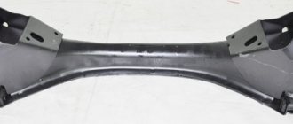
Although from the outside the intake manifold appears to be just a pipeline of a specific shape, in fact a whole team of engineers works on its geometry, calculating the cross-section, length and volume.
Plus, it includes:
- Throttle valve;
- Supply chamber;
- Air filter;
- Inlet valve;
- Discharge chamber.
For engines with distributed fuel injection, injectors are additionally installed in the intake manifold, due to which the mixing of fuel and air masses occurs directly in the discharge chamber.
The pipeline itself can combine from 2 to 12 channels, depending on the number of cylinders in the engine block. At the same time, for a 4-cylinder engine, a manifold with three pipes is sometimes used.
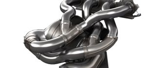
It is also worth noting that most modern intake manifolds over the past 5 years have been made from special high-temperature plastic, while the exhaust manifold can still only be made from metal.
Preparation
VERY IMPORTANT
!
Disconnect the positive wire of the engine under the red cap 1 photo 1
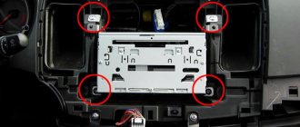
so as not to short anything! And do this with every repair or disassembly in the engine compartment. So, let's begin. What do we need to remove the intake? First of all, remove the plastic decorative cover of the motor (it is mounted on four supports
1 photo 3
).
Sometimes it sits very tightly on its bushings, so there is no need to rip it up madly. It is enough to pick up the lid with one hand, and with the other push the support from the rubber seat 1 photo 2
up from below.
Below it is the air filter housing. It also comes off easily. We remove the chip from the flow meter
1 photo 4
and unscrew
the screw clamp 2 photo 4
with a head on 6 with a small ratchet.
Afterwards, this entire assembly can be removed entirely by pulling up the filter housing from the rubber supports 2 photo 2 and photo 3
in front and towards you to remove it from the supports at the back.
Pulls out without difficulty. You can remove the filter housing separately by unhooking the flow meter snorkel 3 photo 3
from it.
What are swirl flaps used for?
As you know, it is not the fuel itself that burns in the cylinder, nor the air. The air-fuel mixture is burning. And the more homogeneous this mixture is, the better it burns, the higher the efficiency and economy of the engine. Accordingly, the question arises: what is the best way to mix this very fuel in the cylinder? Nozzles that supply fuel not with one large and thick stream, but even with a dozen small streams protrude from one side. And on the other side we have air supplied. And if this air is applied with force, and even at a tricky angle, you get a whirlwind. Which will mix everything perfectly and burn just as well.
But then the engineers faced a question: if they make the hole for the air supply narrow, then at low speeds the vortices will be excellent. But when the speed increases, too much air deficiency will form and too much energy will be spent on its supply. If you make the hole wide enough to operate at medium and high speeds, then there will be no swirl at low speeds, and the engine efficiency will again decrease.
Therefore, for optimal engine operation in all modes, the air supply was divided into 2 parts. In one part there are no dampers, and it is always freely blown, while the second part has the same damper that is completely closed at low revs and opens wider the higher the revs.
The figure shows a diagram of the operation of swirl flaps at low speeds. Air is supplied through only one channel. The second channel is completely closed.
As the engine speed increases and the engine requires more air, the second damper gradually opens slightly, controlling the strength of the air flow. A fully open throttle at high speeds is shown in the figure below:
The position of the swirl flaps is controlled by an integrated sensor and a corresponding drive that changes the angle of inclination of these flaps.
Check Engine
Often, a decent amount of air leaking through the joints of the intake pipe even causes the Check Engine indication to appear.
The corresponding error code will indicate that the air-fuel mixture is too lean. Other culprits for this problem are worn gaskets at the junction of the pipeline and the cylinder head. Often, a decent amount of air leaking through the joints of the intake pipe even causes the Check Engine indication to appear. The corresponding error code will indicate that the air-fuel mixture is too lean. Other culprits for this problem are worn gaskets at the junction of the pipeline and the cylinder head.
Constructive
Metal intake manifolds are cast as a single unit or made into multiple parts. In the latter case, the connections are sealed with sealant or gaskets are installed. Accordingly, they can always be updated by halving the composite manifold.
Plastic collectors are always composite. Production technologies do not allow producing such units as monolithic ones. In most cases, such collectors are actually non-separable: the joints of the connections are soldered. Although there are still more thoughtful designs with the ability to painlessly separate into parts and replace rubber gaskets.
Action plan
As a rule, the joints of plastic elements are more capricious. If the collector is dismountable, then its tightness can be easily restored. True, in most cases the assembly has to be removed from the engine. And in the case of a “monolithic” collector, you will have to think about ways to seal it.
The most reliable option is plastic welding. This is a technology that, for example, is used to repair cracks and tears in bumpers. However, this option can be expensive when it comes to large restoration areas. In this case, it is sometimes cheaper to buy a new or used manifold. If you do this on your own, you will have to spend money on expensive equipment: a special construction hair dryer and a Dremel (straight grinder or drill).
A simpler option is to arm yourself with a soldering iron and solder a plastic seam onto the joint. For example, pieces from a plastic measuring bucket for liquids are suitable for this. All you really need here is patience.
The quickest and easiest way is to seal the joints with sealant. True, this method is least preferable for supercharged engines. Their intake air pressure in some operating modes is significantly higher than that of atmospheric engines. Therefore, any sealants can weaken, and soldering is more suitable for a supercharged engine.
Tuning
Tuning and changing geometry are two different things. When people talk about modifying the intake manifold, they usually mean increasing the incoming air volume and reducing the resistance along its path.
For this purpose the following procedures are provided:
- Replacing the air filter with a zero resistance filter. Thanks to the macroscopic holes in the latter, air is retained less and, accordingly, the speed and volume of passage increases;
- Enlargement of the throttle pipe. It also aims to increase air permeability. Usually, for this purpose, a damper is installed from another engine, which is more powerful than the original;
- Installation of a sports receiver. Short tubes with a larger cross-section, when properly configured, can reduce the pulsation of air masses, which allows the engine to gain speed faster.
There is also a tuning option when the intake manifold is completely removed and short pipes tuned to high speeds are installed instead. This option is provided only for naturally aspirated engines and is called a multi-throttle intake (that is, each cylinder essentially has its own manifold).
By the way, any changes in the intake system usually entail upgrading the exhaust manifold, camshaft and firmware of the electronic control unit.
This is interesting: Antifreeze - domestic antifreeze in all its details
Why do you need to clean the diesel intake from soot?
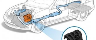
Among the reasons for air pollution in the countries of the former CIS, one of the most important is the low quality of fuel, its low cetane number and additional impurities. All this entails increased formation of soot and coke. We must not forget that to reduce exhaust toxicity, modern diesel engines are equipped with an EGR valve.
When the engine load is light, through this valve some of the combustion products enter the intake tract and mix with the air supplied to the combustion chambers. About 15 percent of exhaust gases are contained in the total mass of the fuel-air mixture. Since there is no oxygen in the exhaust, the combustion time of the mixture slows down, and at the same time the combustion temperature decreases. This leads to a decrease in nitrogen oxide in the exhaust.
In addition to environmental functions, the recirculation system reduces the risk of detonation when the diesel engine runs on a lean mixture. This system is turned off when the engine is running at a high constant load.
The EGR valve is installed not only on diesel engines. BMW owners often encounter problems - the sensor in the manifold becomes covered with dirt and does not work properly. But practice shows that cleaning the BMW X5 H57 intake manifold helps resolve the issue.
Not only soot, but also oily dirt is formed in the intake, since the manifold is also contaminated with products from the crankcase ventilation. So, this dirt actively contaminates the entire manifold, including the EGR valve. If the latter hangs or completely jams, the entire volume of exhaust gases may go into the intake.
Malfunctions
Like any other mechanical part, the intake manifold is susceptible to failure. Given the simplicity of the design, there are not many options for malfunctions.
Basic:
- Violation of tightness. Vibrations, pressure and high temperatures destroy seals over time. Depressurization affects the quality of the fuel mixture, loss of traction and speed. The problem is solved by replacing the gaskets, after which engine operation should return to normal;
- Collector contamination. Plaque accumulates on the walls, gradually reducing the cross-section of passing air masses. Requires disassembly and cleaning of tubes, throttle and discharge chamber;
- Mechanical damage. If the collector is made of plastic, it is only a replacement. If it is made of aluminum and the damage is small, argon arc welding will help;
- Excessive temperature in the manifold. There are a lot of reasons and you need to look for them in the cooling system, clogged radiator, damaged sensor, ECU error. Also, high temperature occurs due to the banal heat outside;
- "Clap." When forming the fuel mixture, the system must be sealed. If there are disturbances in the ignition system, the gas distribution mechanism, problems in the fuel mixture formation chamber, or the tightness of the intake manifold itself is broken, you can hear those same pops. It is worth looking for reasons in all of the above places.
In the latter case, of course, it is easier to rely on the errors reported by the ECU or sign up for a comprehensive diagnostic service.
Restoration work
Repair
In order to repair the intake manifold, you must first dismantle it. Of course, there are situations in which you can do without this. But such manipulations are usually temporary. For example, when you eliminate air leaks using sealant.
The process of removing the intake manifold from under the hood of the car does not take much time. Provided that everything is done correctly. First, find where your fuel pump is located. Then remove the fuse. Your next action will be to start the engine.
The result of starting the engine will be a decrease in pressure: after working a little, the engine will stall. Only then can you disconnect the battery. Next, to dismantle the intake valve you will need to perform the following steps.
- Remove the casing from the motor.
- Disconnect the pipes from the air filter. Remove the filter itself.
- Unscrew the throttle assembly. At the same time, you should not touch the damper fasteners, as they are extremely easy to damage.
After you complete the steps described above, the collector itself should appear before your eyes
Particular attention should be paid to square tubes. If they peel off a little, you need to make two holes in the collector
This way you can get to the damaged element.
During repairs, some difficulties may arise with the valve and dampers. If they are in a damaged condition, they cannot be replaced separately. You will have to completely replace the entire device.
Be sure to check the condition of the sensor. It doesn't take much effort to replace it. It is quite conveniently located, and its installation and dismantling does not take much time.
Cleaning
A knocking sound from the intake manifold clearly indicates that the part is clogged. To resume normal operation of the device, you must perform the following steps.
- Place the car on a lift.
- Remove the manifold bolt that secures it to the frame.
- Remove the throttle valve.
- Remove tubes and sensors.
- Unscrew the bolts securing the part to the engine.
- Carry out dismantling.
- Remove the cover.
- The device consists of two parts. You need to unscrew the bolts and separate them.
- Place the part in a bucket of white spirit solution. Use a brush to remove all dirt.
- Before assembling the structure together, coat the adjacent parts with sealant.
At this stage, collector cleaning is completed. All you have to do is install everything back. At the same time, it won’t hurt to change the gaskets and clean the throttle valve. Also remember to put the sensors in place.
The video shows cleaning the intake manifold:
The manifold is an important part of the car, the performance of the engine depends on its operation. At the same time, its repair is not particularly difficult, as is cleaning. Just follow the instructions and the engine will start working at full speed again.
Lada Kalina from ZR park
Lada Kalina 2 from the ZR park
Lada Kalina 2 from the ZR park
Are there any volunteers?
Armed with theory, we will repair the intake system on the editorial Kalina. The composite plastic path of the 1.6 naturally aspirated gasoline engine (106 hp) leaks around the perimeter of the wells for the ignition coils. Apparently, these are the consequences of frequent tests on the Smolensk Ring race track, in which the car and especially its engine were driven to the limit of their capabilities.
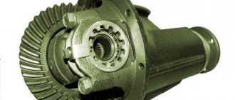
How does he work
The intake manifold is a complex structure that allows fuel and air into the engine.
Upon arrival, they are distributed into streams depending on the number of cylinders in the engine. Moving pistons create a vacuum that reaches a maximum at its lowest point. This creates a virtual vacuum, which neutralizes the crater gases.
The intake system has changed greatly during the evolution of the automotive industry.
So, its structure has come to us in its current form:
- frame;
- air intake;
- pipe branch;
- throttle valve;
- muffler;
- intake manifold;
- pad.
It turns out that the collector itself is part of an important system that ensures the proper functioning of the engine. Its place is on the left side of the cylinder head. To monitor the pressure and temperature inside, sensors are installed on it. The calculations are carried out by the control unit, which also generates commands.
One of the functions of the intake manifold is the redistribution of the fuel-air mixture between the cylinders in the engine.
The main problem for all car enthusiasts was overheating of the intake manifold; for this reason, heated air expands, and its input volumes are significantly reduced. Thus, fuel consumption increased, and the quality characteristics of the engine decreased. Then the technicians decided to make most of the structure from plastic, which alleviated the problem. But still, in order to avoid breakdowns and other troubles, this compartment must be cleaned in a timely manner.
How to check engine air leaks
Finding air leaks will be difficult if you don’t have a special device at hand to show leaks. One of these devices is called a smoke generator; it makes diagnostics much easier and is not that expensive.
Previously, air leaks were determined by eye. We spilled liquid on the intake manifold while the engine was running and looked for bubbles. If you have extensive experience working with a given brand of car, then you can use this method. The downside is that while the engine is running, liquid spilled on the collector will also bubble due to temperature and you can make a mistake. If at this moment the internal combustion engine is shaking, the situation becomes more complicated. If there is a slight loss of tightness, this test option may not help.
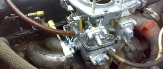
You can check the air leaks on the carburetor by covering the top with your hand or a rag, having first removed the housing with the filter. If the engine stalls, there are no leaks. If it continues to work, then there is an air leak and it needs to be eliminated. As a rule, on the carburetor, a lower plate leads along the plane, which is tightened with the manifold. It can be sanded or replaced with a new one. This procedure is sufficient to determine whether the carburetor is leaking.
Let's return to modern cars, where checking air leaks can take a long time and detecting a leak is not easy. The basic principle of detecting air leaks in the engine is to inject smoke into the intake manifold, which will come out where there is a crack, a loose pin or a torn rubber band. Checking an internal combustion engine with a smoke generator takes some time and takes place in several stages:
- Finding the inlet fitting or any other location on the intake manifold. This is necessary to connect the device itself and supply smoke. It can be difficult to find such an input and you have to use the vacuum booster channel on the intake manifold. With this connection, it is impossible to determine the air leakage from the shaft.
- Next, you need to fill the smoke generator with engine oil. The operating principle is based on heating the oil with a diesel glow plug. You can use any motor oil you have on hand. The main thing is not to overheat the candle, constantly turn the power on and off, or install a pulsed source.
- The standard design of the smoke generator involves supplying air to build up pressure through a compressor. You can use an electric pump from a car, or any other that creates a pressure of at least 1 atm.
- Plug the inlet pipe between the throttle body and the air filter. You can use the housing from an old mass air flow sensor. Fill it with polyurethane foam and you will get an excellent plug.
- Having completed all the preparatory procedures, turn on the device. After smoke under pressure fills the receiver and intake manifold, an air leak will immediately appear. It is advisable to use a flashlight to better see the smoke coming out and the location of the leak.
A smoke generator can be used not only for diagnosing cars and air systems. And also for finding leaks in mattresses, inflatable pools, etc.
Thus, it is easy to check air leaks with a smoke generator. This is a very important and convenient procedure for troubleshooting the engine. Many diagnosticians ask questions about fuel correction when air leaks occur. This is one of the general indicators on the scanner and can indicate not only a leak, but also low compression and shifted valve timing.
There are other ways to check for air leaks with smoke. One of them is using a cigarette. There is even a special tool for this. It is a pistol for a compressor with an internal clip into which a cigarette fits. When you press the trigger of the pneumatic pistol, the cigarette lights up and emits copious smoke. The disadvantage of this method is that it burns out very quickly and there may not be enough time to catch air leaks in the engine and injector. But this option of checking air leaks with a cigarette also has its place.
You can determine air leaks in any engine using the old-fashioned method, by spilling liquid on the intake manifold and the injector area. Or the option with a cigarette, but all these methods are not accurate and not convenient.
The smoke machine itself costs a lot of money. Therefore, if your internal combustion engine shakes or the speed fluctuates, go to a service center that has a smoke generator. They will definitely help you identify the cause without extra costs.
silicone sealant
Universal silicone sealant.
Most of these tubes are equipped with a convenient nozzle. By cutting off part of the spout, you can select the desired diameter of the hole so that the sealant fits well into the joints. Universal silicone sealant. Most of these tubes are equipped with a convenient nozzle. By cutting off part of the spout, you can select the desired diameter of the hole so that the sealant fits well into the joints.
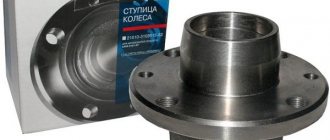
Ramp
Replacing the cathode collector on a VAZ 2110
The ramp is removed as an assembly with the fuel pressure regulator:
- It is necessary to disconnect the vacuum hose from the regulator.
- Using 2 open-end wrenches 17, unscrew the fittings securing the gasoline supply pipes to reduce pressure.
- Disconnect the ramp voltage connector.
- Using a screwdriver, unscrew the screw of the bracket for fastening the gasoline supply and outlet pipes and disconnect it.
- Using a No. 5 hexagon, unscrew the 2 screws for fastening the ramp.
- Pull the ramp in the axial direction of the injector from the seat, remove the ramp towards the left side of the hood.
Note: follow the direction of travel of the vehicle.
Replacement cathode collector for VAZ 2110
- Unscrew the nut from the left intake manifold bracket and loosen the lower bolt.
- Remove the bracket from it.
- Perform the same operation with the right bracket and remove it.
- Unscrew the 2 nuts from the eye stud.
Removing the intake manifold on a 16 valve Kalina
Replacing the O-rings of the Lada Kalina 8kl manifoldRead more
Removing the intake manifold on Grant 16kl. 21126.More details
How to remove the intake manifold of a Grant 16 valve 126 engineRead more
Kalina 1.4 removal of injectors is clear in 10 minutes.Read more
Removing the intake manifold of a VAZ 21 14 .16 valve engineRead more
Removing the intake manifold for 127 internal combustion engines on Priors 2Read more
Priora se removal of receiver and injectors with fuel rail 16 vMore
Removing the intake manifold Lada Kalina 16-valveRead more
How to remove the Kalina 16-valve manifoldRead more
removing the VAZ 16 valve ramp without removing the manifoldRead more
Removing the plastic receiver of a VAZ 2110 PRIORA without air conditioningRead more
Lada Granta removal and installation of intake manifoldRead more
Source
We dismantle the intake module to check the injectors if it is necessary to remove the fuel rail, as well as in other cases when repairing the engine.
To complete the work, you will need an inspection ditch or overpass.
1. Remove the throttle assembly and relieve fuel pressure.
The throttle assembly can be removed without disconnecting the hoses. It is enough to disconnect it from the inlet module flange.
2. Disconnect the throttle valve cable from the intake module.
3. Disconnect the wiring harness blocks from the ignition coils and move the harness to the side.
4. Disconnect the camshaft position sensor wiring harness connector and move the harness to the side.
5. After loosening the clamp, remove the vacuum brake booster hose from the intake module pipe.
6. Removing the air intake of the air filter
7. 8 mm wrench , loosen the clamp securing the crankcase ventilation system hose and remove the hose from the cylinder head cover pipe.
8. Using a short Phillips screwdriver, unscrew screw 1 securing the guide tube of the oil level indicator.
9. We take out the guide tube along with the oil level indicator from the engine cylinder block and remove it.
10. 10 mm wrench , unscrew two nuts 1 securing the intake module to the cylinder head cover and three bolts 2 securing the ignition coils of the first, second and third cylinders.
I. Remove the ignition coils of the first, second and third cylinders
12. Remove the engine splash guard or crankcase protection (if installed).
13. 13 mm socket wrench , unscrew three nuts 2 and two bolts 1 securing the intake module to the side surface of the engine cylinder head.
14. Move the intake module forward and remove the fuel rail.
15. Remove the intake module from the engine.
Install the intake module in reverse order. We replace damaged o-rings of the intake module.
Source