The technical condition of the vehicle's chassis is largely determined by the correct setting of the steering wheel angles. The angles of the steering wheels perform certain functions when the vehicle is moving.
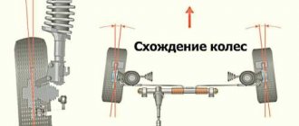
In order to reduce driving resistance, and hence fuel consumption, and reduce wear on tires and suspension by reducing the dynamic loads acting on them, the steered wheels must roll in vertical planes parallel to the longitudinal axis of the vehicle. An important factor in increasing the stability of a car is the stabilization of the steered wheels, i.e. their tendency to return after turning to a position corresponding to the straight-line movement of the car. Taking into account the listed factors, car wheels are installed with angles of toe, camber, longitudinal and transverse inclination of the axle, with a difference in the internal and external angles of rotation of the steered wheels.
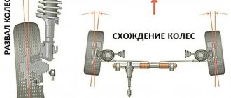
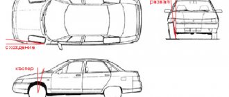
Rice. Steering wheel angles
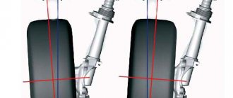
Camber angle
The camber angle is the angle between the plane of the wheel and a vertical plane parallel to the axis of the car and is considered positive if the top of the wheel is tilted outward from the vertical plane. It is necessary to ensure the perpendicular arrangement of the wheels when a loaded vehicle moves in relation to the road surface in the presence of gaps in the articulated joints and deformation of the front axle parts under the influence of the masses of the front part of the vehicle. When installing wheels with a camber angle, the road reaction force is mainly transferred to the inner wheel hub bearing, which is usually larger than the outer one, which relieves the outer wheel bearing and, therefore, reduces the shocks transmitted to the steering mechanism.
When the axle is tilted transversely, it is always more difficult to turn the wheel than to return it to its original position - moving in a straight line. This is explained by the fact that when turning the wheel, the front of the car is raised by a small amount, and the driver applies a relatively large force to the steering wheel.
When the steering wheels return to the straight-line position, the weight of the vehicle helps the wheels turn and the driver applies a slight force to the steering wheel.
However, if there is camber, the wheel tends to roll from the longitudinal axis of the car in an arc around the point “O” where the extension of the wheel axis intersects with the plane of the road. To eliminate this phenomenon, the wheels are installed with toe-in, i.e. not parallel, but at a certain angle to the longitudinal axis of the car.
Violation of the wheel camber angle leads to one-sided wear of the tire tread. If the camber angle is greater than normal, the outer side of the tread wears out and, conversely, if it is less than normal, the inner side of the tread wears out. In addition, a significant difference in the camber angles of the right and left wheels causes the car to pull towards the wheel with greater camber.
Rice. Steering wheel camber angle
During vehicle operation, the camber angles of the steering wheels change due to wear of the front suspension joints, front wheel hub bearings and deformation of the front suspension cross member.
What does the procedure for adjusting a car's wheel alignment mean?
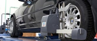
Wheel alignment is the process of adjusting the angle of the tires relative to the road surface and the angle of the trajectory with the torsion plane. The angles need to be adjusted because over time, deformation of the axles, load on the car, operation in extreme conditions on dirt roads or rocky terrain leads to changes in the positions of the angles.
The alignment process involves aligning the tires and cluster. It must be done at specialized service stations. Experienced mechanics install machines on cord stands or make geometry using 3D computer models.
At home and in an ordinary garage, without special equipment, this procedure will take a lot of time. Moreover, this work is painstaking. An incorrect angle change of 4 mm, unnoticed by the unlucky driver during adjustment, will constantly move the car twenty degrees towards the wheel on which the error was made.
Therefore, experts do not recommend adjusting tires for those who do not have experience. However, if at a service station they brush off adjusting wheel alignment, then with sufficient experience and understanding of the axle geometry procedure, you can make the adjustment yourself.
Wheel toe angle
The toe angle of the wheels (the difference in distances between the inner surfaces of the rear and front parts of the tires of the front or rear axle (B - A)) is necessary in order to ensure parallel rolling of the wheels, since when the car moves, due to the installation of cambered wheels, a force arises that contributes to turning the wheels at an angle of 0.5-1.0 from the vertical plane of the car, which leads to the wheels rolling in diverging arcs. In addition, the toe-in angle protects the wheels from slipping if there is play in the steering rod joints and wheel bearings.
The toe angles of the wheels change due to wear of the hinge joints of the steering linkage and deformation of its levers.
The toe angle of the wheels causes increased stepwise wear of the tread with the formation of sharp edges directed towards the longitudinal axis of the vehicle (at an increased angle) or outwards (at a reduced angle).
A characteristic feature of the suspension of front-wheel drive cars is close to zero or even negative values of the camber and toe angles of the wheels. The location of the front wheels at such angles ensures that they are parallel when moving, when torque from the car engine is transmitted to them.
Materials for adjustment
You will need the following materials:
- a regular ruler (if you have one, a telescopic one is better). Since telescopic allows you to adjust the distance. If a regular ruler is suitable for finding the external size, then a telescopic ruler is convenient for measuring the internal distance between tires;
- plumb line - some kind of weight that can be tied to a rope. A regular fishing sinker will do;
- rope or cord to which the sinker will be tied.
It is advisable to install the car in a hole or on a flat surface. The whole procedure consists of two stages:
- camber adjustment;
- toe adjustment.
Moreover, wheel alignment on the front tires of the vehicle is done exactly in the sequence in which the steps are indicated above.
Attention! If the car owner is not confident in his abilities, then it is better to leave the adjustment to specialists at a service station.
Angle of longitudinal inclination of the axis of the rotary rack
The longitudinal inclination angle of the rotary rack axis is determined by the amount of inclination of the upper end of the axis back from the vertical.
Thanks to the longitudinal inclination of the axis, the wheel is installed so that its fulcrum relative to the axis of rotation is moved back by a certain amount and the wheel always tends to take its original position, that is, the position of the car when moving in a straight line. This value is the shoulder of the lateral force that occurs when turning, as a result of which a stabilizing moment is created, which tends to turn the wheel around the axis and return it to its original position. This ensures better stability and stabilization of the steered wheels when the vehicle moves in a straight line.
However, the stabilization of the steered wheels also depends on the elasticity of the tires. The more elastic the tires, the greater their deformation and the greater the torque tending to turn the wheel to a neutral position.
Consequences of incorrect wheel alignment
Increasing the angle beyond the permissible limit, but not crossing the mark, leads to: • accelerated wear of the tread; when the toe-in angle increases by 3 times, the tires can fail after 2–4 thousand kilometers on a passenger car; • to premature wear of oil seals, bearings and steering and suspension pins; • rapid fatigue on the road, when the car constantly has to be caught and leveled.
When the sign of one of the control parameters changes, the car sharply loses directional stability and is prone to skidding and changing direction when braking. This leads not only to premature wear of tires, suspension components, steering elements, but also to emergency situations.
Angle of transverse inclination of the rack axis
The angle of transverse inclination of the rack axis is determined by the angle formed by the rack axis, the upper part of which is deflected inward, with the vertical plane. The angle is considered positive if the bottom of the axis is tilted backwards.
This axle tilt, together with the camber angle, reduces the distance between the point of intersection of the geometric axis of the suspension with the road and the point of the center of contact of the tire, i.e. The arm A of the moment that must be applied when turning the wheels of the car decreases, which means it makes it easier to control the car.
Rice. Axle tilt angle
This angle also helps to improve the stabilization of the vehicle's front wheels, especially at low speeds. Due to the lateral tilt, when the car turns, the front part of the car rises slightly. The mass of the raised part of the car tends to return the wheel after turning to a position corresponding to straight-line motion.
The difference between the internal and external steering angles is necessary to prevent the wheels from slipping when turning them.
Incorrect settings of the camber, toe and rotation angles of the wheels lead to the fact that at the points of contact of the wheels with the road they not only continue to rotate, but also partially slide along it. Wheel slippage leads to increased tire wear and additional energy costs. Inaccurately set angles of transverse and longitudinal inclination of the axle disrupt the stabilization of the wheels. In this regard, the contact patches of the tires of the left and right wheels are located differently in relation to the projection of the turning axis onto the road plane.
At car service centers, to determine wheel alignment angles, they use:
- dynamic (fixing diagnostic parameters of the rotating wheels of the car)
- static (for checking the wheel alignment angles of a stationary vehicle) stands
Is adjustment necessary and why?
Experts answer the question “Do they do camber on the rear wheels of a vehicle?” They answer unequivocally: “Yes!” Because if adjusted incorrectly, the car will:
- eat rubber faster;
- do not allow the driver to control;
- not stable when driving at high speed on the highway;
- bad cornering.
Attention! Manufacturers do not recommend wheel alignment on the rear wheels on modern foreign cars. They advise replacing the entire assembly.
Dynamic stands
The principle of operation of dynamic stands is as follows. The wheels of a car, when driving through the stand area or rotating on its rollers, create a lateral force when the tires come into contact with the supporting surface, which is recorded by special devices. Based on the type of support-receiving devices, dynamic stands are divided into roller (drum) and platform. The main disadvantage of dynamic stands is the low measurement accuracy. With their help, you can only comprehensively evaluate the installation of wheels, which makes it difficult to determine element-by-element faults.
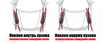
The concept of wheel camber and its effect on driving performance
Every driver has heard that camber can be either negative or positive. Today we will try to figure out what a negative camber angle is and in what cases it occurs. Let's start with the fact that this is a special angle at which the wheels are set, and it directly affects the safety and control of the car, as well as the degree of tire wear. Therefore, this angle can be recognized by looking at the vehicle from the front and in relation to the road surface.
If you draw a conditional line through the center of the wheel from top to bottom and strictly perpendicular, then this will be a zero value. Positive camber is when the top of the wheels points outward, while negative camber is when the wheels point inward or toward the center of the car.
Static stands
Static stands allow you to measure toe-in, camber, longitudinal and transverse inclination of the king pin (axle) with fairly high accuracy. Based on the type of measuring devices, these stands are divided into:
- optical-electrical;
- electronic;
- laser
Optical stands
Relatively good accuracy in measuring the angles of steering wheels is provided by optical stands , in which the positions of the wheels are determined using a mirror or projector mounted on the wheels in the plane of their rotation.
Projection optical stands for determining the angles of steering wheels provide for the installation of measuring heads on the front wheels of the car to the disks, each of which has two projectors.
Scales with divisions are installed on the rear wheels of the car using adapters. A longitudinal light beam is projected onto the scales, and the mechanic can visually read the toe angles of the front axle wheels.
Rice. Projection optical stands for determining the angles of steering wheels
After installing the projectors, wheel alignment is determined using two scales installed at equal distances in front and behind the wheels. Light marks are projected alternately onto both scales by rotating the projector 180°.
Rice. Diagram of a projection optical stand for determining the alignment angles of car wheels: a – measuring device; b – installation of the projector; c – scale of the measuring device; 1 – wheels; 2 – projectors; 3 – scales; 4 – light beams; 5 – screen; 6 – lines of light marks on the screen
The camber angle α is measured using the lower scale of the screen 5. To do this, a light mark is projected onto the end of the arrow A of the screen, then the projector is rotated 180°. The line of light marks 6 on the screen forms a camber angle a with the vertical.
The angle of transverse inclination of the axis is determined by projecting a light mark from the end of arrow B.
The longitudinal inclination angle γ of the kingpin is determined by the change in the camber angle of the wheel when it is turned all the way to the right and left. On screens 5 there are special scales for determining changes in the angles of rotation of the left and right wheels.
Relatively inexpensive laser stands are also used at car service enterprises, the general view of which is shown in the figure:
Rice. Components of a laser stand for checking vehicle wheel alignment angles: 1 – mirror holders (brackets); 2 – mirrors; 3 – turntables; 4 – BKU; 5 – BKU guides; 6 – swivel brackets; 7 – lift ladder; 8 – lifting devices; 9 – translucent screens; 10 – holders with a mirror for checking skew and parallel displacement of bridges; 11 – adjustment rods; 1 – voltage converter; 13 – adjustment ruler
The main element of the stand is the corner control unit (ACU), the general view of the front part of which is shown in the figure.
Rice. Angle control unit: 1 – hydrostatic level; 2, 7, 8 – screws for adjusting the orientation of the block in space; 3 – front target; 4 – screen; 5 – switch; 6 – scales for reading the angles of longitudinal and transverse inclination of the steering axes of the wheels
The BKU is designed to form a laser beam and determine wheel alignment angles. For this purpose, on screen 4 there are vertical and horizontal scales for reading the toe-in and camber angles with a five-minute scale, two scales 6 for reading the angles of the longitudinal and transverse inclination of the wheel axes also have a five-minute scale. The BKU is equipped with a hydrostatic level 1, adjusting screws 7,8,2 for the orientation of the block and screws for adjusting the direction of the laser beam.
The features of carrying out control measurements on the stand are as follows. The car is first installed on the stand strictly parallel to its longitudinal axis (deviation no more than ±5′). To check the angles of the steered wheels, holders with mirrors are installed on each of them with the front axle of the car hanging (the centers of the mirrors must be in the center of the wheels). Using the provided three screws, each mirror is adjusted to be parallel to the wheel disk so that, when rotated by hand, the laser beam reflected from the mirror falls into some five-minute square of the BKU and does not go beyond its limits.
Wheel alignment parameters are measured at a constant (for different car models) distance between the BCU screen and the mirror mounted on the wheel. This distance is equal to 862 mm and is set according to a linear pattern by moving each BCU along specially provided guides.
To measure toe-in, by rotating one of the wheels, the laser beam spot is aligned with the central vertical line of the scale of the corresponding BCU, and the toe-in angle of the wheels is determined from the position of the laser beam spot on the horizontal axis of the second BCU. Accordingly, the camber angle is determined, but according to the position of the laser beam spot relative to the vertical axis of the BKU scales. To measure the longitudinal angle of the steering axis, one of the wheels is turned so that the laser beam hits one of the camber measuring scales. This reading is recorded. Then the wheel is turned until the laser beam appears on the camber scale opposite (from the center of the BCU). Similarly, based on the difference in readings, the longitudinal angle of the wheel is determined, but in position II, when the control units are located in front of the car.
The axle misalignment is measured in position II and at distances from the translucent screens to the central axis of the rear axle equal to 862 mm. The skew angle of the axles is determined by the distance h between the entrance spot and the rear projection of the beam on a translucent screen, and the measurement is carried out for both wheels of the rear axle of the car.
To measure the parallel displacement of axles, translucent screens are installed in the center of the front and rear wheel rims of the vehicle being tested. Parallel displacement is determined by the difference between the readings on the front and rear screens, taking into account the width of the vehicle's wheels.
When determining the misalignment of the rear axle of a car, projectors are mounted on the rear wheels, and additional screens are mounted on the front wheels. In this case, the position of the front wheels must correspond to the linear movement of the car. If there is no misalignment of the rear axle, the absolute values of the deviations of the light marks on the left and right additional screens should be equal.
The disadvantages of the above methods include low accuracy and low speed of measurements. Due to the impossibility of simultaneously measuring the parameters of the front and rear axles, during operation it is necessary to move the front measuring heads to the rear wheels. In addition, the operation time increases significantly due to the need for a large number of auxiliary calculations. When working on such stands, there is no possibility of automatically comparing measurement results with the values recommended by manufacturers.
Electronic stands for checking steering wheel alignment angles
Currently, electronic stands are widely used to check steering wheel alignment angles . Their main advantages include high technology and operation, good metrological characteristics, the ability to display information about measurement results on digital and analog indicators, on a display screen, digital printing and various types of storage devices, etc. The use of electronic stands allows you to check installation angles not only the front, but also the rear wheels, which is necessary for some car models.
Electronic stands of the first models are equipped with four measuring heads, which use potentiometric sensors. The kinematic connection between the potentiometers on adjacent heads, necessary for changes, is provided with the help of special rubber bands (cords) with hooks at the ends, which are hooked onto the levers of the potentiometers before carrying out work. Cord stands have higher accuracy compared to optical ones, and the interface boards they contain allow you to display the values of all measured parameters on the monitor and automatically compare the obtained values with those recommended by the manufacturer. Information is transferred between the credential heads and the central module via wires.
At a higher level there are stands that use infrared radiation for measurements. Compared to cord ones, they have higher measurement accuracy, and they do not have connecting wires between the measuring heads. Instead of potentiometers, sources are installed on each head, connected to each other through an infrared radiation channel. Each head has a matrix of special sensitive elements. The electronic system determines which of them is “exposed” by a transverse source beam from the opposite head; and based on the distance from the “exposed” element to the center of the matrix, the amount of toe-in for each of the wheels is determined. Infrared rays directed along the car serve to determine the longitudinal axis of its symmetry. Equipping such a stand with a personal computer allows, among other things, to save the results of the adjustments made.
An example of such an electronic stand is the Microline 400 stand, the general view of which is shown in the figure. The stand is equipped with charge-coupled sensors, which allows measurements without the use of connecting wires and transmitting data via infrared communication channels.
Rice. General view of the electronic stand for checking the steering wheel alignment angles: 1 – monitor; 2 – keyboard; 3 – graphics tablet; 4 – body
The stand has an electronic unit that receives signals from measuring heads mounted on all wheels of the car.
Rice. Measuring head
The operating principle of the program stored in the memory of the stand and the measuring system is based on the use of a pointer on a graphics tablet.
Rice. Graphic tablet: 1 – tablet menu; 2 – pointer
As a rule, a lift is used in conjunction with the stand. Before determining the wheel alignment angles, the measuring heads are installed in a strictly horizontal position relative to the lift plane using special levels. Information about the position of the measuring heads mounted on the wheels of the vehicle relative to the horizontal and vertical planes of the lift is transmitted to the electronic unit.
The analyzed signals in the form of digital, alphabetic or graphic information are received on the display screen. Based on the information received, appropriate adjustments are made. To compare standard and actual parameter values, the relevant information on makes and models of cars is stored in the memory of the electronic unit. If information is missing, it can be entered.
A constantly updated database of cars from different countries with tolerances for basic parameters, diagrams and animation of adjustments is built into the stand’s memory unit. A customer archive is also maintained, in which data for each vehicle and adjusted parameters are stored. Upon completion of the work, a printout is issued with the measurement results, as well as standard parameter values.
Rice. Printout with measurement results
Laser stands
Currently, computer stands using 3D technologies , for example, “Gelioner”, “Techno Vector 7” - (Russia).
A stand of this type consists of a personal computer 1 and a stand 4, on which a crossbar with two cameras 3 with a built-in video system moves in the vertical direction.
Rice. General view of the stand using 3D technologies: 1 – computer; 2 – laser beam; 3 – camera; 4 – stand; 5 – target
Special reflectors (targets) 5 are hung on the wheels of the car, representing marks in the form of a circle or rectangle made on a square. The reflectors are passive, meaning they operate without any electronic or radio connections. Each camera is controlled by two video cameras: one tracks the front target, the other tracks the back. From the camera, a laser beam illuminates the circles of the square (target) with a flash twice a second and, reflected, hits the video system camera. Cameras synchronized with the appearance of flashes record the image of the marks. At the same time, the car rolls forward and backward by 15...25 cm. Depending on the position of the targets installed on the wheels (which depends on the angles of the car’s wheels), the projection of the reflective elements on the photosensitive matrix of the camera also changes. Based on the degree of change in the projection of the reflective elements on the matrix, the system calculates all angles of the car’s wheels.
The stand measures geometric parameters with an accuracy of 1 mm at a distance of 6 m, calculates the trajectories of the marks and determines the position of the rotation axes of all 4 wheels.
When the wheels are turned by 11..13º, the difference in wheel rotation angles is measured.
Rice. Installing targets on car wheels
The main feature of the stand is the elimination of operations for hanging wheels and compensating for runout, which significantly reduces inspection time.
The data bank of steering wheel alignment angle parameters and body geometry contains information on 5,000 or more cars with drawings of the location of adjustment. In addition, recommendations are given on the adjustment procedure, the tool used and the necessary consumables.
Rice. Recommendations for the adjustment procedure and the tool used
The computer processes the received information, compares it with the standard and shows a digital and graphic display of the wheel alignment angles. The direct measurement process takes about 4 minutes.
The measurement programs of the Helioner stand include simultaneous automatic measurement of the rolling radii of 4 wheels of a passenger car with a graphical representation of the difference in readings. Having a graphical representation of the geometric parameters, when making the appropriate adjustments, you can immediately observe changes in the parameters.
Rice. Stand monitor screen
The “Gelioner” stand also allows you to determine the condition of the body by the points of body position parameters characteristic of each car, which are stored in the memory of the data bank.
Rice. Body position measurement
It is also possible to measure the rolling radii of 4 wheels of a car with a graphical representation of the difference in readings.
Rice. Measuring rolling radii
After measurements, the program presents the radii of all 4 wheels, the difference between the left and right wheels, the difference between the front and rear wheels.
The stand also allows you to determine a three-dimensional spatial image of the linear values of the track, base and diagonal distances. Having the values of the geometry of the body, chassis and steering wheel alignment angles, it is possible to determine with high accuracy not only the current state of the specified vehicle parameters, but also to evaluate the condition of the body when assessing its damage, for example in an accident, and also to evaluate the quality of repair of a damaged vehicle.
Rice. Measuring base, track and diagonal distances
For the first time for stands for measuring the geometric parameters of the body and chassis, the Helioner stand uses voice control of the measurement process in any language or dialect. This allows you to reduce the time spent on moving the worker to the stand to give commands. Example: An operator is adjusting rear wheel toe and requires adjustment data. It is enough to give commands by voice: “Indications”, “Increase” and “Adjustment”.
The main advantages of the stand are that there is no need for an absolutely horizontal plane, the elimination of labor-intensive operations of hanging wheels and compensating for runouts, and the absence of connecting cables.
The most advanced technologies for checking steering wheel alignment angles are robotic systems, for example WAB 01 (Germany). Such a system includes a special scissor lift with electronic synchronization of platform movement and measuring heads installed on it. Before the vehicle enters the lift, the turntables and rear platforms automatically take a position corresponding to the distance between the axles of the vehicle being serviced, which is selected from the database. The heads have a drive that allows them to move from one axle to another and automatically find the centers of the wheels of the vehicle being tested. Measurements are made without operator participation: the measuring head has an adapter in the form of a three-rayed star, the support legs of which are automatically brought to the wheel rim. At the base of the adapter there are sensors that allow the wheel alignment angles to be determined by their position on the wheel.
The vehicle remains stationary during the measurement process, and its wheels are automatically rotated due to the multidirectional movement of the front turntables and rear platforms built into the lift platforms.
The use of electronic stands allows you to check the alignment angles of not only the front, but also the rear wheels, which is necessary for some car models.
Why are the wheels on a car at an angle?
The forced deviation of installation angles from the ideal has several aspects that are not related to each other, so engineers choose their exact value depending on the priorities set by the development of a particular car.
It's even possible that someone might need zero angles, although in practice this would only happen by chance.
Here are some of the influencing factors:
- historical, which arose when the roads were more likely to have a rounded carriageway in profile than to be flat, and were also very dirty and slippery;
- requiring special handling characteristics on sports, racing and simply fast cars;
- the need to ensure stability of movement, without distracting the driver by continuous steering;
- cross-country ability factor, there is not always smooth asphalt under the wheels;
- features of the suspension, ensuring comfort requires it to have elastic connections;
- minimizing tire tread material consumption;
- saving fuel by reducing rolling losses.
All these problems can be solved by simple but precise adjustment of the wheel alignment angles. The task is somewhat complicated by their large number and not always intuitive connections between them.
Operating principle of dynamic stands
The principle of operation of dynamic stands is as follows. The wheels of a car, when driving through the stand area or rotating on its rollers, create a lateral force when the tires come into contact with the supporting surface, which is recorded by special devices. Based on the type of support-receiving devices, dynamic stands are divided into roller (drum) and platform. The main disadvantage of dynamic stands is the low measurement accuracy. With their help, you can only comprehensively evaluate the installation of wheels, which makes it difficult to determine element-by-element faults.
The most widespread in the Republic of Belarus are dynamic on-site stands MINC.
Such stands are a platform that can be moved laterally. If the car wheel is not optimally positioned at its angles, when moving, a lateral force arises in the area of its contact with the road, which will displace the area. This shift is determined by meters per 1 kilometer.
Rice. The principle of determining the position of the wheels
Pad displacement indicates the overall condition of the chassis and steering.
The stand has a frame structure designed to drive a wheel through its movable control platform in a given direction and measure its horizontal movement in a direction perpendicular to the direction of travel.
Rice. Design of the stand for express diagnostics of wheel position: 1, 2, 3, 6, 7 – skids; 4 – measuring sensor; 5 – measuring plate; 8 – shift device; 9 – guides; 10 – box.
The main design elements of the stand are a plate on which the wheel of the vehicle axle being tested passes, a slide used to move the plate, and a shift device. The shift device is connected to the measuring plate and can move along guides. In turn, a measuring sensor is connected to the shift device, which is a potentiometer that records the amount of shift and the direction of movement of the plate when a car passes over it.
The location of the vehicle on the platform is determined by a presence sensor located under the moving platform.
Rice. Presence sensor: A – sensor placement; B – sensor.
When driving over a measuring plate installed at floor level, it is pushed to the right or left depending on the movement of the wheel. This deviation is shown on the screen. The measurement results are recorded automatically sequentially (first for the front axle and then for the rear axle) and are marked in different colors.
Rice. Vehicle wheel alignment control data
Positive test results are displayed in green, wheel slip is within the range of 0...7 m/km, satisfactory condition is displayed in orange within 7...14 m/km, unsatisfactory in red, if the wheel slip is more than 14 m/km or the results of the wheel slip are negative.
Unsatisfactory test results indicate malfunctions of the tires, wheels, suspension, steering or the need to adjust the steering angles. Site stands are characterized by high productivity, since the control time is determined by the duration of travel of the sites by the front wheels at a speed of 3...5 km/h.
To more accurately determine the steering wheel alignment angles, it is necessary to use static stands at a separate post.
Toe adjustment procedure
Steps to adjust wheel alignment:
- Set the front ones straight.
- Make marks on the inside of the tire.
- Use a telescopic ruler to find out the distance from the mark on one tire to the mark on the other.
- Drive forward or backward and measure the distance again.
- Compare the result.
- If the convergence is in the direction of decreasing size, then in the language of mechanics, this result is called negative. If the convergence is in the direction of increasing size, then this is a positive value.
Now it will be necessary to set the optimal values using steering rods. If the result is negative, the optimal dimensions are established by shortening the rods, and if the result is positive, by lengthening them.
Now you need to resize the dimensions. If a discrepancy is found, continue the adjustment.
After the adjustment has been made, you need to put the wheels in place, tighten the bolts and drive the vehicle 10 kilometers. Observe how the car will behave.
If the car continues to move to the side while driving on a straight highway, you need to repeat the adjustment or contact a service center.
Adjusting the toe of the front wheels
Adjustment of the toe-in of the front wheels of all passenger cars is carried out by changing the length of the rods due to the rotation of the adjusting couplings of the steering linkage.
Rice. Front wheel toe adjustments
After adjustment, the couplings are tightened with nuts or clamps. When adjusting, it is necessary to change the length of the left and right rods by the same amount, otherwise the initial position of the steering wheel will change. Wheel toe can be measured in both millimeters and degrees. For some cars, the toe-in of not only the front but also the rear axle is adjusted by installing special rubber-to-metal hinges with an offset axis of the suspension arms.
The required angle of inclination of the axle is set with adjusting washers located between the axis of the lower arm and the cross member, removing them from one axle and adding them to the other (VAZ, Opel), or with eccentric bolts of the suspension arm with the front bolt fastening nuts loosened (Mercedes). The camber angle is set using adjusting washers, adding or removing them simultaneously from both axles (VAZ, Opel), or eccentric bolts (Mercedes, Moskvich - 2141, VAZ - 2109).
Rice. Adjusting the camber of the front wheels and securing the strut joint: 1 – stabilizer joint; 2 – back cup; 3, 4 – nuts; 5 – hinge fastening bolt; 6 – cover flange; 7 – adjusting bolt
The angles of rotation of the wheels are regulated by the position of the adjusting bolts that limit the angle of rotation.
For certain passenger cars, the installation angles are adjusted by turning the upper telescopic strut while loosening the nuts of its fastening (Volvo). For some car models (BMW), only wheel toe adjustment is provided.
When adjustments are needed
If a car owner exhibits the following signs of discrepancy in angles when driving a vehicle, then the car must be taken for adjustment:
- the car pulls to the side when driving straight;
- after suspension repair;
- with large tire wear on one side;
- when the car owner brakes and the car pulls to the side;
- changing tires for winter or summer;
- when the driver bought and installed wheels of a different size on the car;
- after hitting a rock or diving into a large hole.
If the car owner decides that he can adjust the wheel alignment on the front and rear wheels on his own, then the following instructions will help him with this.
Questions on the topic
Filter:AllOpenSolvedClosedWaiting for response
Why does the car start to drive on the highway above 60 km? Answered by User answered 8 months ago
23 views 1 answer. 0 vote.
Strongly eats the inside of the front wheels of the Honda Accord VII Answered by User Answered 8 months ago
26 views 1 answer. 0 vote.
There is not enough front wheel camber adjustment on the Volkswagen Touareg, what are the reasons? Answered by User answered 8 months ago
24 views 1 answer. 0 vote.
What should the wheel alignment angles be on a Toyota Opa? Answered by User answered 8 months ago
25 views 1 answer. 0 vote.
What are the wheel alignment parameters on the Chevrolet Viva? Answered by User answered 8 months ago
25 views 1 answer. 0 vote.
Ask a Question