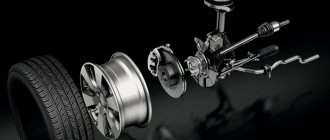
Dimensions of the mandrel for installing the clutch
The overhaul and assembly of my new contract engine is coming to an end; I’ll tell you more about the results.
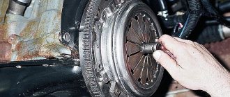
Now it was time to install the clutch. Having assembled one normal one from two sets, I begin to screw the basket to the flywheel and think: “what will I use to center the disk?” I couldn’t find a single suitable frame in the nearest stores. The only option for a universal plastic frame from Johnsway for 590 rubles did not impress me at all: it’s scary that this miracle will crumble upon first use. I started looking through all the tubes in the garage, but couldn’t find any with a diameter of 20mm. And then it dawns on me! After all, I have a lot of scraps of polypropylene pipes left from water supply and heating, and the connections to the mixers are made with the 20th pipe. Those. with an outer diameter of 20mm. I find a piece of such a pipe in the scraps, insert it into the toothed holder of the clutch disc - perfect! I push it deeper - the pipe fits into the crankshaft groove with tension.
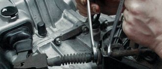
All that remains is to stretch all the basket bolts in a circle in several steps and the disk is perfectly centered. Several tricks are important! If you immediately tighten each bolt completely, the disk will certainly move and you will not be able to pull out the mandrel. Therefore, I tighten each bolt in turn until there is slight resistance, and I go around in a circle several times until the basket fits snugly against the flywheel, but I don’t tighten it all the way.
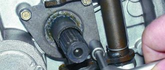
And now I do the following: I unscrew the bolt completely, add a drop of thread locking agent and tighten it back until it stops with a force of 15 Nm. And so on in turn with each bolt.
The clutch is perfectly centered and securely secured.
Be sure to check with the seller about product availability in the store before visiting. Store phone: 8(495)532-43-90
Features: Precision machined mandrels allow you to quickly and accurately align the clutch disc to the flywheel Fits most clutch discs on most passenger cars and light trucks Metric and imperial sizes. →
If you are planning to buy a mandrel or a kit for centering the clutch disc in Moscow, just call us, and our managers will answer all your questions, as well as select the optimal tool for you, based on your needs and capabilities. You can also leave a request through the website using product photos, reviews and popularity ratings. We will contact you as soon as possible to agree on the timing and cost of delivery of the tools you have chosen.
Source
Clutch Maintenance and RepairAt each maintenance check the fluid level in the clutch release reservoir and the free play of the clutch pedal. If necessary, add fluid and adjust the free play of the clutch pedal.
Adjusting the free play of the clutch pedal. The free play of the clutch pedal should be 20-30 mm, which corresponds to a free play of the working cylinder pusher of 4-6 mm and a gap of 2 mm between the friction ring of the thrust flange and the clutch release clutch bearing (see Fig. 124). The free play is adjusted with tip 5 (see Fig. 123), which is fixed with nut 6. Before adjusting the free play of the clutch pedal, you need to make sure that there is a gap of 0.1-0.5 mm between the pusher and the master cylinder piston. This gap, required to completely disengage the clutch, is set by limiter 14 (see Fig. 122) and is determined by a light touch of the pusher on the piston or a free play of the pedal of 0.4-2 mm. Full pedal travel is not adjustable. It is approximately 140 mm and is ensured by setting the gap between the pusher and the master cylinder piston, adjusting the pedal free play and the design of the master cylinder drive.
Bleeding the hydraulic clutch. The presence of air in the hydraulic drive is determined by incomplete disengagement of the clutch, by “softness” and “sagging” of the clutch pedal. To remove air from the hydraulic drive:
Check the fluid level in the hydraulic drive reservoir and add fluid if necessary.
Place a hose on the head of fitting 9 (see Fig. 123) of the working cylinder, the lower end of which is immersed in hydraulic fluid (30-50 g) poured into a clean vessel, unscrew fitting 9 half a turn.
Press and release the pedal sharply until air bubbles stop escaping from the hose. Then, pressing the pedal, tighten the fitting as far as it will go, remove the hose and put on the fitting cap.
If, despite prolonged pumping, air bubbles come out of the hose, it is necessary to check the reliability of the connections, find out if there are cracks in the tubes or leaks in the connections with the fittings. Air may enter through faulty master or slave cylinder O-rings.
When bleeding, you must ensure that the fluid level in the reservoir is above the hole for the tube going to the master cylinder, and that the end of the hose used for bleeding is constantly immersed in the liquid.
Repair
Removing and installing the clutch. You must first remove the gearbox, then apply marks on the clutch housing and flywheel so that their relative positions do not change after assembly. After this, unscrew the bolts securing the clutch housing to the flywheel and remove the clutch mechanism. In this case, you must not lift it by the thrust flange of the pressure spring.
Installing the clutch is carried out in the reverse order. In this case it is necessary:
Rice. 125. Mandrel A.70081 for centering the clutch driven disc
Rice. 126. Centering the clutch driven disc using mandrel A.70081: 1 - flywheel: 2 - clutch assembly; 3 — mandrel A.70081
check the condition of the bearing at the end of the engine crankshaft and replace if necessary;
Place the driven disk with the protruding part of the hub towards the gearbox;
center the driven disk using mandrel A.70081 (Fig. 125), simulating the splined end of the gearbox drive shaft (Fig. 126), and tighten the bolts securing the clutch housing to the flywheel;
Clean the splined end of the gearbox drive shaft with solvent, lubricate it with a thin layer of LSC-15 grease and install the gearbox.
Clutch control is carried out on a base simulating an engine flywheel, with a metal intermediate ring 8.2 mm thick replacing the driven disk (Fig. 127). Having secured the clutch cover, perform four release strokes, applying a load of 135 kgf to the thrust flange of the pressure spring. A shutdown stroke of 8 mm should correspond to a movement of the pressure plate of 1.6-1.7 mm (the smallest allowable is 1.4 mm).
Rice. 127. Installation of the clutch housing assembly for checking and adjusting: 1 - thrust flange of the clutch release drive; 2 — pressure diaphragm spring; 3-pressure disk; 4 - ring
The distance from the base to the working surface of the friction lining of the thrust flange for the new clutch is 40-43 mm. During operation, due to wear on the pressure plate, this size increases; if it reaches 48 mm or the movement of the pressure plate is less than 1.4 mm, the clutch housing assembly with the pressure plate, diaphragm spring and thrust flange should be replaced. The imbalance of the replaced set should not exceed 250 g>mm.
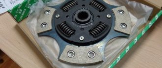
The friction linings of the driven disk should be replaced when cracking appears, when the distance between the rivet and the working surface decreases to 0.2 mm, or when scuffing on one side. In this case, the old rivets are drilled out (drill diameter 3.5-3.7 mm). The runout of the working surface of the friction linings should not exceed 0.5-0.7 mm. Otherwise, the disk is straightened or replaced with a new one. If cracks appear on the driven disk or damper springs, the driven disk assembly should also be replaced.
Removal and installation of the main and slave cylinders of the clutch drive. Before removing the master and slave cylinders, you must first drain the working fluid. To do this, put one end of the hose on fitting 9 (see Fig. 123) of the working cylinder, and lower the other into a clean vessel. Having unscrewed fitting 9 half a turn, press the pedal until the fluid is removed from the hydraulic system. Then disconnect the tubes connecting the main and working cylinders and remove the working cylinder, adhering to the following order: disconnect the release spring 1 (see Fig. 98), remove the cotter pin from the end of the pusher, unscrew the two bolts securing the working cylinder to the clutch housing, and remove Cylinder.
To remove the master cylinder, unscrew the two nuts that secure it on studs to the pedal bracket, and disconnect the flexible reservoir hose by removing the mounting clamps. To install the master and slave cylinders, perform the above operations in reverse order.
After filling the hydraulic drive with working fluid, it is pumped. Disassembly, repair, inspection and assembly of the main and working cylinders. Main cylinder. Remove the protective rubber cap 17 (see Fig. 122) from the end of the cylinder body and the retaining ring 18; this will allow you to remove the piston 9, o-ring 8, floating piston 7, ring valve 20 and piston return spring 23 from the body.
Check the condition of the cylinder mirror and the outer surface of the piston, which should not have any damage or marks, and remove them by cleaning. In this case, the internal diameter of the master cylinder should not change. Check the condition of the piston return spring and replace it if it has lost its elasticity.
Replace the seals. Check the protective cap at the rear end of the cylinder and, if the cap is damaged, replace it with a new one. Before assembly, carefully clean and rinse the parts with hydraulic fluid. Do not allow mineral oil, gasoline, kerosene or diesel fuel to come into contact with parts, as these substances will cause rubber seals to swell.
After checking all the parts, reassemble the master cylinder in the reverse order of disassembly, and lubricate all parts of the cylinder only with hydraulic fluid.
Working cylinder. Remove the protective rubber cap 12 (see Fig. 123) together with the pusher 4, remove the piston and disassemble it, first removing the retaining ring 18 and unscrewing the fitting 9. After disassembly, carefully rinse and check all parts, as indicated for the main cylinder. Installation of a deformed pusher is not allowed.
Having completed the check, proceed with assembly (the reverse order of disassembly), lubricating the parts with hydraulic fluid.
Read more about VAZ cars...
What is a clutch disc holder
Application of clutch disc holder
Aligning the clutch disc using a universal mandrel
The clutch disc mandrel (clutch disc centerer) is a device for centering the driven disc relative to the flywheel and/or pressure plate when repairing a single-plate clutch in vehicles with a manual transmission.
When to change the clutch
No one can say the exact rules for replacing the clutch. The service life of the unit directly depends on the level of wear of certain elements, driving style, and the quality of the parts.
The difficulty is that it is impossible to directly check the wear of the pressure plate, driven or flywheel without dismantling the gearbox.
The first signs of clutch wear appear no earlier than 30-40 thousand after the previous replacement:
- The clutch does not engage completely. This indicates that the driven disk has worn out, has lost the nominal thickness of the friction linings and cannot engage in frictional engagement with the flywheel. In other words, the clutch is constantly slipping.
- Clutch basket wear manifests itself in a similar way. In this case, you can detect wear on the pressure surface of the basket and destruction of the spring petals.
- Worn release bearing. Accompanied by the same symptoms, but against the background of a strong noise when pressing the pedal or releasing the pedal. Sometimes the noise of the release bearing disappears when you press the clutch pedal, which also indicates wear on the release bearing.
- Flywheel wear. In the most advanced cases, the flywheel can wear out so much that the force of the clamping springs is not enough to press the driven disk to the surface of the flywheel. The symptoms are the same - the clutch slips, the linings overheat with a characteristic odor.
The danger of driving with a worn clutch is not only that the driver cannot fully control the transmitted torque to the gearbox. When the friction linings slip at idle, active wear of the working surfaces of the flywheel and basket occurs, as well as their overheating, which can lead to warping and complete failure of the flywheel .
Types, design and features of clutch disc holders
A section of the gearbox input shaft can serve as the simplest mandrel for proper clutch assembly. However, this option is not always available, and it is not convenient, so specially made mandrels are most widely used. These devices can be divided into two large groups according to their purpose:
- Special - for certain cars or clutch models;
- Universal - for various cars.
Centering mandrels of various types have their own design features and operating principles.
Do-it-yourself KAMAZ clutch replacement
To replace the clutch yourself, you will need help removing the gearbox.
Work order:
- Unscrew the fastening nuts, remove the cardan, pneumatic hydraulic booster, and release the starter from the mounting.
- Remove the pipes for the reduction gear, as well as the gear lever.
- Take a jack.
- Place a jack under the engine sump and lift the engine.
- Remove the rear cross member and the spacer rod.
- Release the bracket from the fastening.
- Secure the hoist and tighten it.
- Remove the engine side mounts. Unscrew the gearbox fasteners to the engine.
- Using a hoist, move the gearbox away from the engine until the input shaft comes out, then remove it.
Special clutch disc holders
Mandrels of this type are usually made in the form of a steel rod of variable profile, which can be divided into three sections:
- An end section with a diameter corresponding to the diameter of the central bushing or support bearing of the gearbox input shaft located in the flywheel;
- Central working part with a diameter corresponding to the diameter of the spline hole of the driven disk hub;
- Handle for holding the tool while working.
In general, the special mandrel imitates the end part of the gearbox input shaft, but it is lighter and more convenient to use. Usually the central working part of the mandrel is smooth, but you can find devices with a splined working part. A notch or other corrugation may be applied to the handle to prevent the hand from slipping.
Such a mandrel is installed with its end section into the central bushing or into a bearing in the flywheel, and the driven disk is put on its working part - thus the parts are aligned along a common axis. After installing the clutch basket, the mandrel is removed and its place is taken by the gearbox input shaft.
Universal clutch disc holders
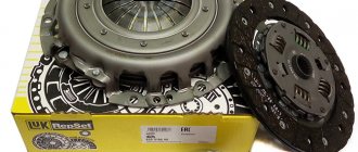
Clutch disc alignment kit
Universal clutch disc holder
Clutch disc cam expansion mandrels
Such devices are made in the form of sets from which mandrels of the required diameter can be assembled. There are three main structural types of mandrels:
- Collet with tapered bushing;
- With replaceable constant diameter adapters and tapered bushing;
- Cam expanders with replaceable adapters of constant diameter.
Collet mandrels are used to center the driven disc relative to the clutch pressure plate. The basis of the device is a steel rod with an expanded conical head and threads on the opposite side. A plastic collet attachment with an extension at the end and four longitudinal cuts is put on the rod. A plastic mandrel body is placed on the nozzle, which has a large thread and a knurled wheel. A plastic cone is screwed onto the body, and a plastic adjusting wheel is screwed onto the threads of the rod. This entire assembly is threaded through a hole in the clutch basket, the end of the nozzle is inserted into the hub of the clutch driven disc. By rotating the adjusting wheel, the rod is pulled into the nozzle, which, due to expansion on the rod, moves apart and becomes wedged in the disk hub. Then a cone is screwed in, which fits into a hole in the basket (or pressure plate), thereby centering the parts. The basket assembly with the mandrel is installed on the flywheel, and after installing the clutch, the mandrel is removed.
Mandrels with replaceable adapters and a tapered bushing ensure centering of the driven disk relative to the flywheel. The device consists of a steel guide rod (pin) with a thread at the end, onto which steel adapters of various diameters are screwed, and then a conical bushing is installed. The rod assembly with the adapter is installed in the central bushing or support bearing in the center of the flywheel, then the clutch driven disc is put on the rod, and then the tapered bushing. By pressing the cone into the disc hub, the parts are centered, after which the clutch basket can be installed.
Cam expansion mandrels also ensure centering of the driven disk relative to the flywheel. This mandrel is made in the form of a rod with a threaded tip on which the adapter is installed. The body of the mandrel contains an expanding mechanism with three cams and a drive from a screw located at the reverse end of the device. As the screw rotates, the cams can move out and into the mandrel. For alignment, a device with an adapter of the required diameter is installed in the central bushing or in the support bearing in the flywheel, then the driven clutch disc is installed on the rod and fixed with cams. Due to the uniform exit of the cams, the disc is centered with the flywheel, after which the clutch basket can be installed.
Adjusting the double-disc clutch basket using a caliper
There is a ring on the paws. Adjusting the double-disc clutch of a Kamaz vehicle requires correctly setting the distance from the outer plane of the pressure ring to the clutch disc. The double-disc clutch is adjusted using a caliper. It is necessary to measure from the metal plane of the disk to the outer plane of the pressure ring.
Many people try to do this from the disc hub. But it's not right. And there are no such sizes. The lock washer on each leg is unscrewed. It is closed with a lid that is attached to two bolts at each adjusting nut. Rotating this nut raises or lowers the clutch tab. The gap is set this way. So that the ring is removed from the disk at the same distance. That is, when rotating the adjusting nuts, the disk must be perfectly level.
Factory distance
The factory default distance from the clutch disc to the top plane of the pressure ring is 65 mm. The clutch works perfectly. All operating angles are observed when the clutch fork is pressed onto the release bearing. The clutch operates smoothly. The clutch pedal is adjustable. The clearance on the PSU rod is also easy to set.
Desired distance
Kamaz is used in agriculture. Removing crops from the fields. It is almost impossible to leave the field without setting the clutch on fire. The disc wears out quickly. Therefore, other car models will not appear in the fields for a long time.
When the clutch disc wears out, the paws come out to meet the release bearing. This increases the gap from the disk to the upper plane of the ring. Therefore, when adjusting, it is necessary to take this into account. And make the gap a little smaller. The best option is 62 mm.
At 62mm, the clutch is also highly adjustable. And the difference from 65 mm is almost invisible. But we still have a margin of 3 mm, which will extend the operation of the clutch until the ring rests the release bearing on the gearbox housing. In this case, the clutch will soon stop working.
Undesirable distance
They say on the Internet. That the optimal size is 57 mm is not true. I tried. At the owner's insistence. He failed to immediately prove the opposite. What happened. The clutch released well. But it became impossible to move off without a jerk. The release bearing fork is in the most extreme position. And when the pedal was released, there was a sharp release of the release pedal. The position of the fork when the clutch is depressed should look like this.
And at 57 mm it became like this.
The fork ends up facing the release lever. Smooth release of the release lever became impossible. There are two options left: either wait until the disk is erased. And the paws will come out on their own. But this will most likely damage the gearbox. Or adjust the clutch locally. This is possible although very inconvenient.