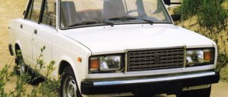
The VAZ-2107 car was produced from 1982 to 2014.
Here are colored wiring diagrams (for the injector and carburetor) with a description of all the elements for various modifications. The information is intended for self-repair of cars. Electrical circuits are divided into several blocks for ease of viewing via a computer or phone; there are also circuits in the form of a single picture with a description of each element - for printing on a printer. The “sevens”, like most modern cars, use a single-wire circuit for supplying electricity to electrical equipment. The other terminal of the consumer is always connected to the ground of the machine to which the negative terminal of the battery is connected. This solution allows not only to simplify the design of the on-board network, but also to slow down corrosion.
VAZ-2107 diagram: first option
Full size wiring diagram:
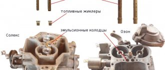
Electrical diagram VAZ-2107 carburetor
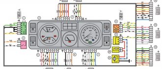
Electrical diagram of VAZ 2107, 21074 produced in 1988-2001 with generator 37.3701
- block headlights
- side direction indicators
- accumulator battery
- starter relay
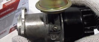
- carburetor electro-pneumatic valve
- carburetor microswitch
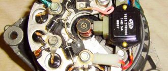
- generator 37.3701
- gearmotors for headlight cleaners *
- Fan motor switch sensor
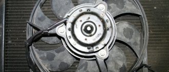
- engine cooling fan motor
- sound signals
- distributor
- spark plug
- starter
- coolant temperature gauge sensor
- engine compartment lamp
- low oil pressure warning sensor
- low brake fluid level indicator sensor
- windshield wiper motor
- carburetor electro-pneumatic valve control unit
- ignition coil
- headlight washer pump motor *
- windshield washer pump motor
- mounting block
- windshield wiper relay
- hazard warning and direction indicator relay
- brake light switch
- reverse light switch
- ignition relay
- ignition switch
- three lever switch
- hazard switch
- socket for portable lamp**
- heater fan switch
- additional resistor for the electric motor of the heater (stove)
- rear window heating indicator lamp
- low brake fluid level warning lamp
- signaling unit
- heater fan electric motor
- glove compartment lamp
- light switches on the front door pillars
- switches for warning lights of open front doors ***
- front door open warning lights ***
- connection block
- cigarette lighter
- watch
- instrument light switch
- diode for checking the serviceability of the low brake fluid level indicator lamp
- fuel level indicator
- fuel reserve indicator lamp
- speedometer
- turn signal indicator lamp
- carburetor choke indicator lamp
- battery charge indicator lamp
- carburetor choke warning switch
- instrument cluster
- econometrician
- light switches on the rear door pillars
- coolant temperature gauge
- tachometer
- indicator lamp for parking brake activation (“handbrake”)
- low oil pressure warning lamp
- high beam indicator lamp
- indicator lamp for turning on external lighting
- voltmeter
- Parking brake indicator switch (“handbrake”)
- outdoor light switch
- rear window heating switch with backlight
- rear fog light switch with on/off indicator *
- fog light circuit fuse
- lampshade ****
- tail lights
- level indicator and fuel reserve sensor
- connectors for connecting to the rear window heating element *
- license plate lights 2107
Wiring diagram VAZ-2107 carburetor - full view:
Tachometer speed does not work - why does the needle “jump”
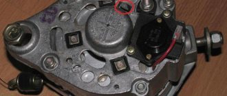
Generator VAZ 2107: operating principle and connection diagram
Here are some tips from experienced car owners:
- look for the Check indicator (if there is no signal, self-diagnosis will not help);
- check connections and voltage with a tester;
- in case of parallel incorrect operation of other devices, test the “ground”;
- inspect the distributor parts;
- check the condition of the circuits;
- If problems occur at high engine speeds, diagnose the switch.
If, as a result of repair work, the tachometer does not work well, adjustment is required (adjusting the “0” position and the unit, checking the quality of connections).
The tachometer on the instrument panel does not work? Replace it. In theory, this is not difficult, but it is better to find detailed video instructions in advance (select the option specifically for your engine - diesel or gasoline).
Before purchasing a unit, be sure to check its compatibility with the machine.
Mounting block connection diagram
P1 — relay for turning on the heated rear window; P2 - relay for turning on the headlight cleaners and washer; P3 - relay for turning on sound signals; P4 - relay for switching on the electric motor of the engine cooling system fan; P5 - headlight high beam relay; P6 - low beam headlight relay; A - the order of conditional numbering of plugs in the mounting block blocks. The outer number with the letter “Ш” in the plug designation is the block number, and the inner number is the conventional number of the plug.
Types of tachometers
Among the many different types of tachometers, only two are particularly popular:
But these two types of measuring instruments have a number of fundamental differences. They also differ in structure, characteristics, and, of course, in method of application. Therefore, it is further worth considering the question of what a tachometer is, based on its type.
Digital tachometer
The main components of a digital tachometer are a number of different parts. This:
- CPU;
- eight-bit ADC;
- liquid temperature sensor;
- LCD screen;
- optocoupler;
- various microcircuits (which perform reset functions).
Typically, electronic tachometers are made in the form of a screen, the main indicators of which are the engine speed per minute. Compared to an analog tachometer, its design has some disadvantages, although the advantages still prevail. First of all, using such a device is much more convenient.
Analog tachometer
The analog tachometer is the most commonly used measuring device, which is installed in most cars of domestic manufacturers, and on foreign cars too. Structurally, the device looks quite primitive - a regular display and arrow. But, guided by its readings, you can understand how to reduce fuel consumption.
The structure of analog tachometers is much simpler than digital instruments. Their main components are:
- magnetic coil;
- a sensor that reads information from the shaft elbows;
- arrow;
- graduated scale.
Similar to the device, analog tachometers work just as simply. The signal from the sensor that reads the number of revolutions of the crankshaft passes through the wires and hits the board, which sets the deviation for the arrow, the arrow in turn shows you the real data through a graduated scale.
True, the measurement accuracy of a digital tachometer is slightly higher. Although, this is only noticeable when adjusting the engine, since while driving the revolutions are counted in the thousands and the error does not matter much. Perceiving the readings of such a tachometer while driving is much easier than reading numbers from the monitor of a digital tachometer.
Schemes of individual blocks of the seven
Power supply system
Power plant starting system
1 - starter; 2 - relay; 3 — ignition switch; 4 - battery
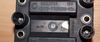
Ignition system
1 - generator; 2 — ignition switch; 3 - distributor; 4 - breaker; 5 — candles; 6 - coil; 7 - battery
Contactless ignition system
External and internal lighting
Windshield wipers and washers
1 — electric motors of the windshield wiper; 2 — washer motor; 3 — mounting block; 4 — ignition switch; 5 - washer switch
Cooling Fan
1 — fan electric motor; 2 - sensor; 3 — mounting block; 4 - ignition relay; 5 - ignition switch.
Wires for connecting electrical appliances
| Connection type | Section, mm2 | Insulation color |
| Negative terminal of the battery - vehicle ground (body, engine) | 16 | Black |
| Starter positive terminal - battery | 16 | Red |
| Positive contact of the generator - plus battery | 6 | Black |
| Generator - black connector | 6 | Black |
| Terminal on the generator “30” – white MB block | 4 | Pink |
| Starter connector “50” – starter relay | 4 | Red |
| Starter Start Relay - Black Connector | 4 | Brown |
| Ignition switch relay - black connector | 4 | Blue |
| Ignition switch output “50” – blue connector | 4 | Red |
| Ignition switch connector “30” – green connector | 4 | Pink |
| Right headlight plug - ground | 2,5 | Black |
| Left headlight plug - blue connector | 2,5 | Green, gray |
| Generator output “15” – yellow connector | 2,5 | Orange |
| Right headlight connector - ground | 2,5 | Black |
| Left headlight connector - white connector | 2,5 | Green |
| Radiator fan - ground | 2,5 | Black |
| Radiator Fan - Red Connector | 2,5 | Blue |
| Ignition switch output “30/1” – ignition switch relay | 2,5 | Brown |
| Ignition switch contact “15” – single-pin connector | 2,5 | Blue |
| Right headlight - black connector | 2,5 | Grey |
| Ignition switch connector “INT” – black connector | 2,5 | Black |
| Six-pin block of the steering column switch - “ground” | 2,5 | Black |
| Two-pin block of the steering column switch - glove box illumination lamp | 1,5 | Black |
| Glove compartment light - cigarette lighter | 1,5 | Black |
| Cigarette lighter - blue block connector | 1,5 | Blue, red |
| Rear window defroster - white connector | 1,5 | Grey |
Useful: Lada Vesta VAZ-2180 diagram
Car wiring diagram
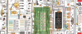
1 – radiator fan drive motor; 2 – relay and fuse block (mounting block); idle speed sensor; 4 – engine control unit; 5 – potentiometer; 6 – set of spark plugs; 7 – ignition control unit; 8 – electronic crankshaft sensor; 9 – electric fuel pump; 10 – tachometer 2107; 11 – lamp for monitoring the health of electronic systems; 12 – ignition system control relay; 13 – speed sensor; 14 – diagnostic connector; 15 – set of injectors; 16 – adsorber solenoid valve; 17, 18, 19 – fuse block protecting the injection system circuits; 21 – electronic fuel pump control relay; 22 – electronic relay for controlling the intake pipe heating system; 23 – intake pipe heating system; 24 – fuse protecting the heater circuit; 25 – electronic oxygen level sensor; 26 – cooling system temperature control sensor; 27 – electronic air damper sensor; 28 – air temperature sensor; 29 – pressure control sensor.
Ignition system
As mentioned earlier, the ignition system of the VAZ 2107 car and the tachometer needle are interconnected; they cannot exist without each other. And if the arrow twitches, and all the above tips did not help, you should pay attention to the condition of the ignition elements. First of all, inspect the wires for damage or lack of contacts.
It is quite possible that there is a break inside the device itself. The photo shows a wiring diagram, study it to get an idea of where the wires go and where they come from. If the power system has a carburetor and a classic ignition system is installed, then it is possible that a breakdown of the capacitor installed in the lower part of the distributor has occurred.
In most cases, the needle jumps if there is a malfunction in the ignition system. It is quite possible that the Hall sensor is malfunctioning. But in this case, unstable engine operation will be felt. If you have an injector, then you should check the condition of the engine speed sensor and all connecting wires.
Very often failures occur after the tachometer has been disassembled or replaced. If you have performed such actions, then you need to carefully check whether the device is installed correctly, is the connection made in accordance with the diagram, is the arrow at zero when the engine is stopped? It is worth noting that there is a toggle switch on the back of the device; it is designed to set the needle to zero.
But there are times when at idle the needle behaves quite well. But at speed, when the speedometer passes the mark of 80 or 100 km/h, the needle begins to twitch strongly. In this case, it is even possible that misfires may occur. This is a sign that there is a breakdown in the ignition switch and it needs to be replaced urgently. That's all that can be said about the device designed to measure crankshaft rotation speed.
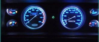
Abstract on the topic “Types of instrument clusters 2107”)))))
Let's look at the general diagram of devices 151.3801
Until 1988, instrument cluster 15.3801 was used
You can find instruments for export cars with a different speedometer scale (with miles)
Tidy 35.3801 for Gazelle and Sable cars is very similar to it
There is a device for UAZ Patriot cars with a slightly different connection
In short, when replacing devices, you can install the wrong one, and something will not show. For injection 2107s of the last years of production there is a tuned electronic device Gamma GF 607 with a trip computer and a astronomical price
The device 110.3801 for UAZ-3162 is not at all similar to the devices 2107
Kind of a conclusion. Although the devices are outdated and prone to breaking, they are still quite informative. At that time, the VAZ-2107 was one of the cars stuffed with all sorts of sensors. At the moment, 2107 devices are subject to collective farm damage due to the “unfashionable” weak and green backlight in our time. People install ugly scales with transparent numbers, glue diode strips inside, not noticing the factory beauty of one of the few instrument clusters at that time (the instruments are combined into one unit and have curved glass to eliminate glare), which appeared in the 80s.
Fuse and relay diagram 2107
On newer “sevens” a block with 17 fuses and 6 relays is installed. VAZ 2107 fuses on the “new” unit protect the following electrical circuits and devices:
- Reversing lamps, heater fan, rear window defroster warning lamp and relay, rear wiper motor and rear washer pump.
- Electric motor for front wipers.
- Reserve socket.
- Reserve socket.
- Power supply for heated rear window.
- Clock, cigarette lighter, power socket “carrying”.
- Signal and radiator fan.
- Turn signal lamps in emergency mode.
- “Fog lights” and a relay that regulates the voltage of the on-board network.
- Instrument panel lamps.
- Brake light bulbs.
- Right high beam headlight.
- Left high beam headlight, high beam warning lamp.
- Side lights (rear right, front left), license plate and engine compartment lighting.
- Side lights (rear left, front right), glove compartment and cigarette lighter lamps.
- Low beam (right lamp).
- Low beam (left lamp).
The block relays perform the following functions:
- Heated rear window relay.
- Headlight cleaner and washer relay.
- Signal relay.
- Cooling system electric fan relay.
- High beam relay.
- Low beam relay.
The fuse block of the VAZ 2107 (injector) is no different from the block on the carburetor “seven”. Injection models are simply equipped with an additional relay and fuse box installed in the cabin under the glove compartment. The block includes three relays - the “main” relay, the fuel pump relay and the fan relay.
DIY replacement instructions
Car owners, as a rule, think about the need to service and repair the tachometer if it fails.
More information about replacing the device:
- Disconnect the battery and use a flat-head screwdriver to pry and remove the three handles installed on the heater control selector.
- Unscrew the nut securing the odometer reset lever, and also remove the washer installed behind it.
- Next, using the same flat-tip screwdriver, pry off the cap of the bolt that secures the tidy. After removing it, unscrew the screw securing the shield to the center console bracket.
- Having done this, move the right part of the tidy to the maximum, then remove the left part. After this you will have access to the back of the shield, now you need to unscrew the speedometer cable nut and completely disconnect it. Next, disconnect all hoses and connectors connected to the shield.
- Remove the dashboard. Remove the tachometer from it and install a new one. If you have connected everything correctly, the installed device will work.
Photo gallery “Dismantling the tidy”
1. Unscrew the instrument mounting bolts.
2. Unscrew the nut securing the speedometer cable.
3. Disconnect the connectors from the device and remove it.
What tachometer do you have?
Survey
- Analog (79%, 131 Votes)
- Digital (21%, 35 Voices)
Total votes: 166
Loading …
Modifications of the VAZ-2107 car
VAZ-2107 . Basic version of the sedan, with an 8-valve carburetor VAZ-2103 engine, 1.5 liters.
VAZ-2107-20 . The same VAZ-2107, but with a 1.5-liter VAZ-2104 injection engine that meets the Euro-2 environmental standard.
VAZ-2107-71 . The car for the Chinese market was equipped with a VAZ-21034 engine, with a volume of 1.4 liters and a power of 66 horsepower, specially tuned for A-76 gasoline. The pistons were taken from a VAZ-2108.
VAZ-21070 . Modification of a car with an 8-valve, carburetor VAZ-2103 engine, volume 1.5 liters.
VAZ-21072 . Modification with an 8-valve carburetor VAZ-2105 engine, volume 1.3 liters.
VAZ-21073 . An export modification for the European market, which was equipped with a 1.7-liter injection engine with a capacity of 84 horsepower. The engine of this car had a catalytic converter that satisfied environmental protection requirements.
VAZ-21074 . Modification with an 8-valve, carburetor VAZ-2106 engine, volume 1.6 liters.
VAZ-21074-20 . Modification with a 1.6-liter VAZ-21067-10 injection engine, which complies with the Euro-2 environmental standard
VAZ-21074-30 . Like the previous model, but with a VAZ-21067-20 engine, which meets the Euro-3 environmental standard
VAZ-210740 . Modification produced in 2010, equipped with a VAZ-21067 injection engine with a catalyst. Engine capacity is 1.6 liters, power is 72.7 horsepower.
VAZ-21076 . Export modification with a VAZ-2103 carburetor engine.
VAZ-21077 . Export modification with right-hand drive for the UK market. The car was equipped with a VAZ-2105 carburetor engine with a volume of 1.3 liters.
VAZ-21078 . Another export modification for the UK, but with a 1.6-liter VAZ-2106 carburetor engine
VAZ-121079 . The modification, developed specifically for the needs of the Ministry of Internal Affairs and the KGB, was equipped with a powerful VAZ-413 rotary piston engine with a volume of 1.3 liters and a power of 140 horsepower.
VAZ-2107 ZNG . The car is equipped with an 8-valve, fuel-injected VAZ-21213 engine with a volume of 1.7 liters.
Tachometer on a VAZ sixth model: to help novice motorists
The tachometer in any vehicle, including the VAZ 2106, is a device necessary for reading crankshaft revolutions. With its help, the driver will be able to determine not only the speed of movement, but also various malfunctions in the operation of the engine, the symptoms of which are associated with jumps in speed. Read more about the principle of operation and malfunctions below.
How does it work?
To understand how the VAZ 2106 plug-in household or car tachometer works, you need to understand what the design of the device is. In accordance with the tachometer diagram, this device belongs to electromechanical type devices. Accordingly, the tachometer connection diagram for a carburetor or injector is combined - the tachometer needle on a VAZ 2106 is driven by impulses. The device itself reads signals that arise during the operation of the ignition system.
The power unit of domestic “classics” operates in such a way that during one revolution of the crankshaft, the contact group of the ignition breaker must close and open 4 times. Accordingly, here you can already understand how the tachometer on a VAZ 2105 or 2106 works - the device needs to count the total number of signals and divide the resulting value by 4.
Six tachometer connection diagram
Where is?
There may be several options for the location of the device; the main requirement in this case is convenience for the motorist. If the VAZ 2106 tachometer is connected at home, then it is usually placed on the dashboard or on the center console, in fact, as in production. Of course, if necessary, you can install the device in any convenient place, but the two options listed above are the most convenient.
Before installing and connecting the tachometer, you need to take into account that the readings shown by the device should always be in sight. While driving, the driver must not be distracted from the road. A digital device can be installed on the “six”, although initially these models were equipped with analog devices.
Possible faults
Why doesn’t the tachometer work, why does the needle on the installed device twitch and jump, how can I check the device myself? We suggest that you familiarize yourself with the list of the most common malfunctions for the device. If you notice that the arrow on the supplied device begins to twitch, then most likely the jump may be due to the inoperability of the capacitor located at the bottom of the breaker. The capacitor may be broken or its contact is very weak. If you notice that there are signs of damage on the device itself, then it would be best to change it (author - Master Ruslan channel).
In some cases, the needle jumps due to the use of a battery that has expired. One of the most common causes of device failure is wear of the cable; in some cases, the problem may occur due to the failure of the coil, but this happens much less frequently. If you are using an analog device, it may not work correctly due to any damage to the microboard. As for digital devices, they are more reliable in terms of operation, but the weak points in such devices are the board with the processor, as well as the signal counter.
Diagnostics can be done as follows:
- Disconnect the wiring supplying the device.
- Turn the key in the ignition.
- If the needle of the device is at 0, this indicates its performance. If the arrow tends to the maximum value, most likely the problem is a short circuit. If the needle very slowly returns to 0, then most likely the reason lies in the breaker capacitor.
Connection features
So that you can understand how the device should be connected, you first need to become familiar with what these or other wires are intended for.
It should be taken into account that the colors of the wires and their purpose may differ depending on the manufacturer of the device, but for the standard “TX-193” device, which is usually used in “sixes”, the diagram is as follows:
- A white cable is required to connect the backlight.
- The red wire is connected to the ignition switch, a fuse is used for this, this cable supplies power when the ignition is activated.
- A white cable with a black break is required for connection to the car body.
- The brown wire connects to the K+ terminal on the coil.
- The black wire is connected to the charging current indicator relay. The latter, in turn, is installed on the right in the engine compartment.
- The gray-black cable is required to connect to the engine fluid pressure regulator installed to the left of the engine.