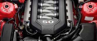
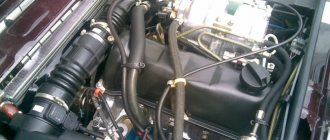
Features of the design of the on-board network of the VAZ 2107
The “sevens”, like most modern cars, use a single-wire circuit for supplying electricity to electrical equipment. We all know that power to devices is supplied through only one conductor - the positive one. The other terminal of the consumer is always connected to the ground of the machine to which the negative terminal of the battery is connected. This solution allows not only to simplify the design of the on-board network, but also to slow down electrochemical corrosion processes.
Current sources
The vehicle's on-board network has two power sources: the battery and the generator. When the car engine is turned off, electricity comes into the network exclusively from the battery. When the power unit is running, power is supplied from the generator.
The nominal voltage of the on-board network of the “Seven” is 12 V, but depending on the operating mode of the engine, it can vary between 11.0–14.7 V. Almost all electrical circuits of the VAZ 2107 are protected in the form of fuses (fuse links). The main electrical appliances are switched on via a relay.
Wiring on-board network VAZ 2107
The combination of electrical devices into one common “seven” circuit is carried out using flexible PVA type wires. The current-carrying cores of these conductors are twisted from thin copper wires, the number of which can vary from 19 to 84. The cross-section of the wire depends on the strength of the current flowing through it. The VAZ 2107 uses conductors with the following cross-section:
- 0.75 mm2;
- 1.0 mm2;
- 1.5 mm2;
- 2.5 mm2;
- 4.0 mm2;
- 6.0 mm2;
- 16.0 mm2.
Polyvinyl chloride is used as an insulating layer, which is resistant to possible exposure to fuel and process fluids. The color of the insulation depends on the purpose of the conductor. The table below shows the connection wires for the main electrical components in the “seven”, indicating their color and cross-section.
All electrical devices of the VAZ 2107 have a single-wire connection
Table: connection wires for main electrical appliances VAZ 2107
| Connection type | Wire cross-section, mm2 | Insulating layer color |
| Negative terminal of the battery - vehicle ground (body, engine) | 16 | Black |
| Starter positive terminal - battery | 16 | Red |
| Positive contact of the generator - plus battery | 6 | Black |
| Generator - black connector | 6 | Black |
| Terminal on the generator “30” – white MB block | 4 | Pink |
| Starter connector “50” – starter relay | 4 | Red |
| Starter Start Relay - Black Connector | 4 | Brown |
| Ignition switch relay - black connector | 4 | Blue |
| Ignition switch output “50” – blue connector | 4 | Red |
| Ignition switch connector “30” – green connector | 4 | Pink |
| Right headlight plug - ground | 2,5 | Black |
| Left headlight plug - blue connector | 2,5 | Green, gray |
| Generator output “15” – yellow connector | 2,5 | Orange |
| Right headlight connector - ground | 2,5 | Black |
| Left headlight connector - white connector | 2,5 | Green |
| Radiator fan - ground | 2,5 | Black |
| Radiator Fan - Red Connector | 2,5 | Blue |
| Ignition switch output “30/1” – ignition switch relay | 2,5 | Brown |
| Ignition switch contact “15” – single-pin connector | 2,5 | Blue |
| Right headlight - black connector | 2,5 | Grey |
| Ignition switch connector “INT” – black connector | 2,5 | Black |
| Six-pin block of the steering column switch - “ground” | 2,5 | Black |
| Two-pin block of the steering column switch - glove box illumination lamp | 1,5 | Black |
| Glove compartment light - cigarette lighter | 1,5 | Black |
| Cigarette lighter - blue block connector | 1,5 | Blue, red |
| Rear window defroster - white connector | 1,5 | Grey |
Find out more about the design of the VAZ 2107 generator: https://bumper.guru/klassicheskie-modeli-vaz/generator/remont-generatora-vaz-2107.html
Bundles (harnesses) of wires
To facilitate installation work, all wires in the car are collected in bundles. This is done either with adhesive tape or by placing the conductors in plastic tubes. The bundles are connected to each other using multi-contact connectors (pads) made of polyamide plastic. To be able to pull wiring through body elements, it is provided with technological holes, which are usually closed with rubber plugs that protect the wires from rubbing against the edges.
The “seven” has only five wiring bundles, three of which are located in the engine compartment, and the other two are in the cabin:
- right harness (stretches along the mudguard on the right);
- left harness (stretched along the engine shield and mudguard of the engine compartment on the left side);
- battery harness (comes from the battery);
- a cluster of the instrument panel (located under the dashboard, and goes to the headlight and turn switches, the instrument panel, and interior lighting elements);
- rear harness (stretches from the mounting block to the aft lighting fixtures, glass heater, fuel level sensor).
There are only five wiring harnesses in the VAZ 2107
Mounting block
All wiring harnesses of the “seven” converge to the mounting block, which is installed in the right rear part of the engine compartment. It contains fuses and relays for the machine's on-board network. The mounting blocks of carburetor and injection VAZ 2107 are almost the same structurally, however, in “sevens” with distributed injection there is an additional relay and fuse block, which is located in the cabin.
The main mounting block is located in the engine compartment
In addition, there are machines equipped with old-style blocks designed for the use of cylindrical fuses.
Old "sevens" have mounting blocks with cylindrical fuses
Let's consider what protection elements ensure the safe operation of the VAZ 2107 on-board network.
Table: VAZ 2107 fuses and the circuits they protect
| Designation of an element on the diagram | Rated current (in old-style/new-style units), A | Protected electrical circuit |
| F-1 | 8/10 | Heating unit fan motor, rear window defroster relay |
| F-2 | 8/10 | Electric wiper motor, headlight lamps, front window washer electric motor |
| F-3 | Not used | |
| F-4 | ||
| F-5 | 16/20 | Rear window heating element |
| F-6 | 8/10 | Clock, cigarette lighter, radio |
| F-7 | 16/20 | Signal, main radiator fan |
| F-8 | 8/10 | Turn signal lamps when the hazard lights are turned on |
| F-9 | 8/10 | Generator circuit |
| F-10 | 8/10 | Signal lamps on the instrument panel, the instruments themselves, turn signal lamps in the turn signal mode |
| F-11 | 8/10 | Interior lamp, brake lights |
| F-12, F-13 | 8/10 | High beam lamps (right and left) |
| F-14, F-15 | 8/10 | Dimensions (right side, left side) |
| F-16, F-17 | 8/10 | Low beam lamps (right side, left side) |
Table: VAZ 2107 relays and their circuits
| Designation of an element on the diagram | Switching circuit |
| R-1 | Rear window heating unit |
| R-2 | Electric motors for windshield washer and wiper |
| R-3 | Signal |
| R-4 | Radiator fan motor |
| R-5 | High beam |
| R-6 | Low beam |
The turn relay in the “seven” is installed not in the mounting block, but behind the instrument panel!
As already mentioned, the injection “sevens” have an additional relay and fuse block. It is located under the glove box.
The additional block contains relays and fuses for power circuits
It contains power elements that ensure the operation of the main electrical circuits of the car.
Table: fuses and relays of the additional mounting block VAZ 2107 injector
| Name and designation of the element on the diagram | Purpose |
| F-1 (7.5 A) | Main relay fuse |
| F-2 (7.5 A) | ECU fuse |
| F-3 (15 A) | Fuel pump fuse |
| R-1 | Main (main) relay |
| R-2 | Fuel pump relay |
| R-3 | Radiator fan relay |
More information about the VAZ 2107 fuel pump: https://bumper.guru/klassicheskie-modeli-vaz/toplivnaya-sistema/benzonasos-vaz-2107-inzhektor.html
Where is the mass from the engine to the body on the VAZ-2114: exact photos of the location
Experienced car enthusiast. I have an automotive education, namely: an engine repair mechanic. At the beginning of my career there was a VAZ-2107, then a BMW 5-series, a Toyota Supra and a right-hand drive MARK-2. Now the family has 2 cars: Peugeot 407 and Dodge Challenger 2016. I study each car from “A” to “Z”. I have a lot of experience and try to repair everything with my own hands.
VAZ 2107 on-board network systems and the principle of their operation
Considering that the “sevens” were produced with both carburetor and injection engines, their electrical circuits are different.
The electrical circuit in the carburetor VAZ 2107 is somewhat simpler than in the injection ones
The difference between them is that the latter have an on-board network supplemented with an electronic control unit, an electric fuel pump, injectors, and sensors for the engine control system.
The injection VAZ 2107 circuit includes an ECU, an electric fuel pump, injectors and control system sensors
Regardless of this, all electrical equipment of the “seven” can be divided into several systems:
- car energy supply;
- starting the power plant;
- ignition;
- external, internal lighting and light signaling;
- sound alarm;
- additional equipment;
- engine control (in injection versions).
Let's look at what these systems consist of and how they function.
Energy supply system
The VAZ 2107 energy supply system includes only three elements: a battery, a generator and a voltage regulator. The battery serves to provide electricity to the vehicle's on-board network when the engine is turned off, as well as to start the power plant by supplying power to the starter. The “sevens” use lead-acid starter batteries of type 6ST-55 with a voltage of 12 V and a capacity of 55 Ah. Their characteristics are quite sufficient to ensure the start of both carburetor and injection engines.
VAZ 2107 was equipped with 6ST-55 batteries
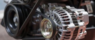
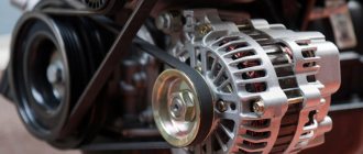
A car generator is designed to provide electric current to the vehicle's on-board network, as well as charge the battery when the power unit is running. Until 1988, “Sevens” were equipped with generators of the G-222 type. Later, VAZ 2107 began to be equipped with current sources of type 37.3701, which had successfully proven themselves on the VAZ 2108. Essentially, they have the same design, but differ in the characteristics of the windings.
The generator generates current to provide electricity to the vehicle's on-board network
Generator 37.3701 is a three-phase electromechanical alternating current device with electromagnetic excitation. Taking into account the fact that the on-board network of the “seven” is designed for direct current, a rectifier is built into the generator, which is based on a six-diode bridge.
The generator is installed on the power plant of the machine. It is driven by a V-belt from the crankshaft pulley. The amount of voltage generated by the device depends on the number of crankshaft revolutions. To ensure that it does not go beyond the limits established for the on-board network (11.0–14.7 V), a microelectronic voltage regulator of the Ya112V type works in tandem with the generator. This is a non-separable and non-regulated element that automatically and continuously smoothes out voltage surges and dips, maintaining it at a level of 13.6–14.7 V.
The basis of the power supply system is a battery, a generator and a voltage regulator
The generator begins to produce current when we turn the ignition key to position “II”. At this moment, the ignition relay is turned on, and voltage from the battery is supplied to the exciting winding of the rotor. In this case, an electromotive force is generated in the generator stator, inducing an alternating current. Passing through the rectifier, alternating current is converted to direct current. In this form, it goes to the voltage regulator, and from there to the on-board network.
Also check out the electrical diagram of the VAZ 21074: https://bumper.guru/klassicheskie-modeli-vaz/elektrooborudovanie/vaz-21074-inzhektor-shema-elektrooborudovaniya-neispravnosti.html
Video: how to find a generator malfunction
Power plant starting system
The VAZ 2107 engine starting system includes:
- battery;
- starter with relay;
- ignition switch (lock).
1 - starter; 2 - relay; 3 — ignition switch; 4 - battery
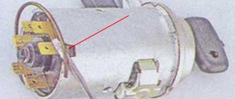
As a device for starting the power unit in the VAZ 2107, a four-brush DC electric starter of the ST-221 type is used. Its circuit does not have protection in the form of a fuse, but it provides two relays: an auxiliary (power supply) and a retractor, which ensures the coupling of the device shaft with the flywheel. The first relay (type 113.3747–10) is located on the engine panel of the machine. The solenoid relay is mounted directly on the starter housing.
The ST-221 starter is installed in the VAZ 2107
The engine start is controlled using the ignition switch located on the steering block. It has four positions, by moving the key to which we have the opportunity to turn on the circuits of various electrical equipment:
- “0” – a position in which all electrical devices are turned off, with the exception of the sound signal, cigarette lighter, interior lamp, and sometimes the radio (depending on how it is connected);
- “III” – exterior headlight lamps, windshield washer and wipers are powered;
- “I” – power is supplied to the ignition system, to the instrument panel, warning lamps and heater fan;
- “II” – current is supplied to the starter relay, retractor and starter field windings.
The engine starts as follows. When the key is turned to position “II,” the corresponding contacts of the ignition switch are closed, and current flows to the terminals of the auxiliary relay, starting the electromagnet. When its contacts also close, power is supplied to the windings of the retractor. At the same time, voltage goes to the starter. When the retractor relay is activated, the rotating shaft of the starting device engages with the flywheel crown and through it transmits torque to the crankshaft.
Using the lock, various circuits of the machine's on-board network are switched on
When we release the ignition key, it independently returns from position “II” to position “I”, and the current stops supplying the auxiliary relay. This opens the starter circuit and turns it off.
Video: if the starter does not turn
Ignition system
The ignition system is designed for timely ignition of the combustible mixture in the combustion chambers of the power plant. Until 1989 inclusive, the VAZ 2107 was equipped with a contact type ignition. Its design was:
- a coil representing a voltage-increasing transformer;
- distributor with contact breaker;
- high voltage wires;
- candles.
1 - generator; 2 — ignition switch; 3 - distributor; 4 - breaker; 5 — candles; 6 - coil; 7 - battery
The ignition coil is used to increase the voltage coming from the battery. The classic (contact) ignition system used a two-winding coil type B-117A, and the contactless one used 27.3705. Structurally they are no different. The difference between them lies only in the characteristics of the windings.
Video: repair of the ignition system of the VAZ 2107 (part 1)
The distributor is necessary to interrupt the current and distribute voltage pulses across the spark plugs. In the "sevens" distributors of type 30.3706 and 30.3706–01 were installed.
By means of high-voltage wires, high-voltage current is transmitted from the contacts of the distributor cap to the spark plugs. The main requirement for wires is the integrity of the conductor and insulation.
Spark plugs produce a spark at their electrodes. The quality and time of the fuel combustion process directly depends on its size and power. From the factory, VAZ 2107 engines were equipped with spark plugs of type A-17 DV, A-17 DVR or FE-65PR with an interelectrode gap of 0.7–0.8 mm.
The contact ignition system worked as follows. When the ignition was turned on, the voltage from the battery went to the coil, where it increased several thousand times and followed the contacts of the breaker located in the ignition distributor housing. Due to the rotation of the eccentric on the distributor shaft, the contacts closed and opened, creating voltage pulses. In this form, the current entered the distributor slider, which “carried” it across the contacts of the cover. These contacts were connected to the central electrodes of the spark plugs via high voltage wires. This is the path the voltage passed from the battery to the spark plugs.
After 1989, the “Seven” began to be equipped with a contactless ignition system. This was due to the fact that the breaker contacts constantly burned and became unusable after five to eight thousand kilometers. In addition, drivers often had to adjust the size of the gap between them, as it constantly got lost.
The contactless ignition system uses a switch instead of a breaker
The new ignition system no longer had any distributor. Instead, a Hall sensor and an electronic switch appeared in the circuit. The operating principle of the system has changed. The sensor read the number of revolutions of the crankshaft and transmitted an electronic signal to the commutator, which, in turn, generated a low voltage pulse and sent it to the coil. There, the voltage was increased and supplied to the distributor cap, and from there, according to the old scheme, it was supplied to the spark plugs.
Video: repair of the ignition system of the VAZ 2107 (part 2)
In the injection-powered "sevens" everything is much more modern. Here in the ignition system there are no mechanical components at all, and the role of the ignition coil is played by a special module. The operation of the module is controlled by an electronic unit, which receives information from several sensors and, based on it, generates an electrical impulse. Then it transmits it to the module, where the pulse voltage increases and is transmitted through high-voltage wires to the spark plugs.
In injection VAZ 2107, the electrical impulse is generated by the ECU
System of external, internal lighting and light signaling
The vehicle lighting and alarm system is designed to illuminate the interior of the cabin, the road surface in the front and rear of the car in the dark or in conditions of limited visibility, as well as warn other road users about the direction of the maneuver by giving light signals. The system design includes:
- front block headlights;
- turn signal indicators (side indicators);
- rear lights;
- salon lamp.
The lighting system includes front and rear headlights, turn signal indicators, and interior lamp
VAZ 2107 was equipped with two front block headlights, each of which combined high and low beam headlights, side lights and direction indicators in its design. Far and near lighting in them is provided by one double-filament halogen lamp type AG-60/55, the operation of which is controlled by a switch located on the steering column on the left. The turn signal unit contains a lamp of type A12–21. It turns on when you move the same switch up or down. The side light is provided by A12-4 type lamps. They light up when you press the exterior lighting switch. The turn signal also uses A12-4 lamps.
The rear lights of the “seven” are divided into four sections:
- direction indicator (lamp A12–21–3);
- side light (A12–4);
- fog light (A12–21–3);
- reversing lights (A12–21–3).
The rear fog lights light up when you press the button to turn them on, which is located on the center console of the car. The reversing headlights turn on automatically when you engage reverse gear. A special “frog” switch installed in the rear of the gearbox is responsible for their operation.
The interior of the car is illuminated using a special lamp located on the ceiling. Its lamp turns on when the side lights are turned on. In addition, its connection diagram includes door limit switches. Thus, the lamp starts to glow when the side lights are turned on and at least one of the doors is open.
The lampshade is designated number 64
Sound alarm system
The sound alarm system is designed to provide a sound signal to other road users. Its design is very simple, and consists of two electric sound signals (one high-pitched, the other low), relay R-3, fuse F-7 and a power button. The sound alarm system is constantly connected to the on-board network, so it works even when the key is pulled out of the ignition switch. It is turned on by pressing a button located on the steering wheel.
1 - high and low tone signals; 2 — mounting block; 3 - power button
The sound sources in the “sevens” are signals like 906.3747–30. Each of them has a trim screw to adjust the tone. The design of the signals is non-separable, therefore, if they fail, they must be replaced.
Video: repair of the VAZ 2107 sound signal
Additional electrical equipment for VAZ 2107
Additional electrical equipment of the “seven” include:
- electric motors of the windshield wiper gear motor;
- windshield washer pump electric motor;
- cigarette lighter;
- heater fan motor;
- radiator cooling fan electric motor;
- watch.
Windshield wiper motors drive a trapezoid, which in turn moves the windshield wipers across the car's windshield. They are installed in the rear of the engine compartment, immediately behind the engine shield of the car. The VAZ 2107 uses gearmotors of type 2103–3730000. Power is supplied to the circuit when the right steering column switch is moved.
The washer motor drives the washer pump, which supplies water to the washer line. In the "sevens" the motor is part of the design of the pump built into the tank lid. Part number 2121–5208009. The washer motor is activated by pressing the right steering wheel switch (towards you).
1 — electric motors of the windshield wiper; 2 — washer motor; 3 — mounting block; 4 — ignition switch; 5 - washer switch
The cigarette lighter, first of all, is not used to allow the driver to light a cigarette from it, but to connect external electrical equipment: a compressor, navigator, DVR, etc.
The cigarette lighter connection diagram consists of only two elements: the device itself and fuse F-6. Switching on is carried out by pressing the button located at the top of it.
The cigarette lighter is connected to the on-board network via a fuse without a relay
The heater fan electric motor is used to force air into the vehicle interior. It is installed inside the heating unit. The device catalog number is 2101–8101080. The electric motor can operate in two speed modes. The fan is turned on with a three-position button located on the dashboard.
The electric motor of the radiator cooling fan is used for forced air flow of the main heat exchanger of the vehicle when the coolant temperature exceeds the permissible values. Its connection diagrams for carburetor and injection “sevens” are different. In the first case, it is turned on by a signal from a sensor installed in the radiator. When the coolant is heated to a certain temperature, its contacts close and voltage begins to flow into the circuit. The circuit is protected by relay R-4 and fuse F-7.
1 — fan electric motor; 2 - sensor; 3 — mounting block; 4 - ignition relay; 5 - ignition switch
In the injection VAZ 2107, the scheme is different. Here the sensor is installed not in the radiator, but in the cooling system pipe. Moreover, it does not close the fan contacts, but simply transmits data on the refrigerant temperature to the electronic control unit. The ECU uses this data to calculate most commands related to engine operation, incl. and to turn on the radiator fan motor.
In injection "sevens" the electric radiator fan is turned on by a signal from the ECU
The clock is installed inside the car on the dashboard. Their role is to show the time correctly. They have an electromechanical design and are powered by the machine's on-board network.
The clock is constantly connected to the on-board network
Engine management system
Only injection power units are equipped with a control system. Its main tasks are collecting information about the operating modes of various systems, mechanisms and engine components, processing them, generating and sending appropriate commands to control devices. The system design includes an electronic unit, injectors and a number of sensors.
The ECU is a kind of computer in which a program is installed to control the operation of the engine. It has two types of memory: permanent and operational. The computer program and engine parameters are stored in permanent memory. The ECU controls the operation of the power unit, checking the serviceability of all components of the system. If a breakdown is detected, it switches the engine to emergency mode and gives a signal to the driver by turning on the “CHEK” lamp on the instrument panel. The RAM contains current data received from sensors.
The injectors are designed to supply gasoline to the intake manifold under pressure. They spray it and inject it into the receiver, where a flammable mixture is formed. At the heart of the design of each of the nozzles is an electromagnet that opens and closes the nozzle of the device. The operation of the electromagnet is controlled by the ECU. It sends electrical impulses at a specific frequency, causing the electromagnet to turn on and off.
The control system includes the following sensors:
- Throttle position sensor. It determines the position of the damper relative to its axis. Structurally, the device is a variable resistor that changes resistance depending on the angle of rotation of the damper.
- Speed sensor. This element of the system is installed in the speedometer drive housing. A speedometer cable is connected to it, from which it receives information and transmits it to the electronic unit. The ECU calculates the speed of the car based on its impulses.
- Refrigerant temperature sensor. As already mentioned, this device serves to determine the degree of heating of the refrigerant that circulates in the cooling system.
- Crankshaft position sensor. It generates signals about the position of the shaft at a certain point in time. This data is necessary for the computer to synchronize its operation with the cycles of the power plant. The device is installed in the camshaft drive cover.
- Oxygen concentration sensor. Serves to determine the amount of oxygen in exhaust gases. Based on this information, the ECU calculates the proportions of fuel and air to form the optimal combustible mixture. It is installed in the intake area immediately behind the exhaust manifold.
- Mass air flow sensor. This device is designed to calculate the volume of air entering the intake manifold. The ECU also needs such data to correctly form the fuel-air mixture. The device is built into the air duct.
The operation of all systems and mechanisms is controlled by the ECU
Information sensors
The information sensors of the VAZ 2107 include an emergency oil pressure sensor and a fuel level indicator. These devices are not part of the engine management system, since the engine can work well without them.
The emergency oil pressure sensor is designed to determine the pressure in the lubrication system and promptly notify the driver when it drops to critical levels. It is installed in the engine cylinder block and connected to a warning lamp located on the instrument panel.
The fuel level sensor (FLS) is used to determine the volume of fuel in the tank, as well as warn the driver that it is running low. The sensor is installed in the gas tank itself. It is a variable resistor, the slider of which is attached to the float. The fuel level sensor is connected to a gauge located on the instrument panel and a warning lamp located there.
Sensors are connected to instruments and warning lamps
Generator device
The design of a car generator provides its own rectifier and control circuit. Using a stationary winding (stator), the generator portion of the generator generates three-phase alternating current, which is then rectified by a series of six large diodes and charges the battery with direct current. Alternating current is induced by the rotating magnetic field of the winding (around the winding or rotor field). Current is then supplied through the brushes and sliding rings to the electronic circuit.
Generator device: 1. Nut. 2. Washer. 3. Pulley. 4. Front cover. 5. Distance ring. 6. Rotor. 7. Stator. 8. Back cover. 9. Jacket. 10. Gasket. 11. Protective sleeve. 12. Rectifier unit with capacitor. 13. Clamp holder with voltage regulator.
The principle of operation of the autogenerator
Connection diagram for the VAZ 2110-2115 generator
generator wiring diagram includes the following components:
- Battery.
- Generator.
- Fuse box.
- Ignition.
- Dashboard.
- Rectifier unit and additional diodes.
The principle of operation is quite simple: when you turn on the ignition plus through the lock, the ignition passes through the fuse box, light bulb, diode bridge and passes through a resistor to minus. When the lamp on the dashboard lights up, the plus is sent to the generator (to the field winding), then when the engine starts, the pulley begins to rotate, the valve also rotates, thanks to electromagnetic induction, an electromotive force is formed and alternating current appears.
Then the diode passes the plus through the sine wave in the left shoulder, and the minus. in the right. Additional diodes to the lamp cut off the minuses and receive only pluses, then it goes to the dashboard, and the diode that is there allows only the minus to pass through, as a result the light goes out, and the plus passes through the resistor and goes into the minus.
The principle of operation of a car DC generator can be explained as follows: a small direct current begins to flow through the field winding, which is regulated by the control unit and maintained at just over 14 V. Most generators in a car can generate at least 45 amperes. The generator operates at 3000 rpm and above. if you look at the ratio of fan belts to pulleys, it will be two or three to one relative to engine frequency.
READ How to Open Vesta If the Battery is Dead
To avoid this, the plates and other parts of the rectifier generators are partially or completely covered with an insulating layer. In the monolithic design of the rectifier unit, the radiators are combined mainly with printed circuit boards made of insulating material reinforced with connecting busbars.
Next, let's look at the connection diagram for a car generator using the example of a VAZ-2107 car.
Main malfunctions of the electrical equipment of the VAZ 2107
As for breakdowns of electrical equipment in the VAZ 2107, there can be any number of them, especially if we are talking about an injection car. The table below shows the main malfunctions associated with the Seven electrical appliances and their symptoms.
Table: faults in electrical equipment of VAZ 2107
| Signs | Malfunctions |
| The starter does not turn on | The battery is low. There is no contact with the "ground". The traction relay is faulty. Break in the rotor or stator windings. The ignition switch is faulty. |
| The starter turns, but the engine does not start | The fuel pump relay (injector) has failed. The fuel pump fuse has blown. A break in the wiring in the ignition switch-coil-distributor section (carburetor). The ignition coil (carburetor) is faulty. |
| The engine starts but is unstable at idle | Malfunction of one of the sensors of the engine management system (injector). Breakdown of high-voltage wires. Incorrect gap between the contacts of the breaker, wear of the contacts in the distributor cap (carburetor). Spark plugs are faulty. |
| One of the external or internal lighting devices does not work | Faulty relay, fuse, switch, broken wiring, lamp failure. |
| Radiator fan does not turn on | The sensor is faulty, the relay is faulty, the wiring is broken, the electric drive is faulty. |
| Cigarette lighter doesn't work | The fuse has blown, the cigarette lighter coil has burnt out, there is no contact with ground. |
| The battery drains quickly and the battery warning light comes on | Malfunction of the generator, rectifier or voltage regulator |
Why did it happen so?
Perhaps the automatic requests do not belong to you, but to another user accessing the network from the same IP address as you. You need to enter the characters into the form once, after which we will remember you and be able to distinguish you from other users exiting from this IP. In this case, the page with the captcha will not bother you for quite a long time.
You may have add-ons installed in your browser that can make automatic search requests. In this case, we recommend that you disable them.
It is also possible that your computer is infected with a virus program that is using it to collect information. Maybe you should check your system for viruses.
If you have any problems or would like our support team, please use the feedback form.
CarFrance.ru » Lada » 2114 » Electrics » Where is the mass from the engine to the body on the VAZ-2114: exact photos of the location
A few more words about the voltage regulator
Finally, it should be added that in cars such as the VAZ 2107, it is necessary to check the voltage supplied from the generator to the battery with a voltmeter at least once a month. We discussed how to do this above. The fact is that a car device that shows the battery charge level very often lies, showing us the norm, while the voltage at the battery terminals during engine operation is lower or higher than it. And here the danger is not so much the lack of charging as the so-called overcharging. It occurs when the voltage regulator malfunctions and is characterized by the supply of voltage to the battery, the value of which is greater than prescribed.
Diagnostics and repair work
If you suspect that the battery is not charging, you need to carry out a series of diagnostic and repair work in this order:
- Stop the car, turn off the engine.
- Raise the hood and check the integrity of the drive belt. If it is intact, check its tension by pressing with a screwdriver or other tool on the belt branch in the middle between the generator and crankshaft pulleys. The deflection in this place should be 12–17 mm.
If the voltage is lower, the cause must be sought in the rectifier, stabilizer or generator windings. In any case, further diagnostics require dismantling the generator.
Video: tensioning the alternator belt
Dismantling the generator
To remove the generator set, you must:
- Open the hood, disconnect the wires from the battery.
- Using a 17 mm wrench (for units type 9412.3701 a 13 mm wrench), completely unscrew the nut securing the device to the adjusting bracket.
Video: removing the generator
Checking the rectifier module, stabilizer and windings
To diagnose the rectifier, regulator and windings, you will need a multimeter and two pieces of wire with clamps. To check, you need to carry out the following work:
- Switch the multimeter to resistance measurement mode.
- Connect the positive probe of the device to terminal “30” of the device, and the negative probe to its “ground”. The resistance between these points may vary, but if it is close to zero, the windings may be shorted to ground or one of the rectifier diodes may be broken.
Generator repair
If problems are detected with the rectifier module or windings, the faulty part must be replaced. To do this you will need:
- Use a screwdriver to secure the generator impeller by resting one of the blades against it.
- Using a socket or 19 mm socket wrench, unscrew the pulley fixing nut.