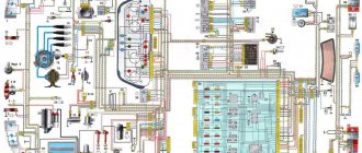
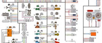
Electronic circuit of the car IZH 2126
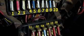
List of fuses IZH 2126 “Oda”
Blocks of both the old and the newest (with knife-shaped fuses) standard can be installed on the square. Blocks of different designs are not interchangeable.
Fuse number (current, A) Electronic circuits protected by fuses
4(16) Radiator fan relay coil. Electrical circuit of switches and electric motor of the heater
5(3) Hazard switch (in turn signal mode), turn signal switch, turn signal switch Turn signal warning lamp, turn signal warning lamps Reversing light switch, reversing lamps Tachometer Voltmeter Fuel gauge, fuel level sensor, warning lamp Fuel level Temperature indicator! cooling water Temperature sensor Control lamp and emergency oil pressure sensor Brake system emergency lamp Hydraulic brake switch Parking brake switch
6(8) Brake light switch and lamps Interior lighting
7(8) Lamps for the license plate light Control pump for turning on the side lighting Lamps for illuminating the heater and cigarette lighter levers Lamp for lighting the glove box Switch and lamps for illuminating the arrangement of devices
8(16) Horn, horn switch Radiator fan motor
9(8) Side light bulb for left headlight Side light bulb for left rear light
10(8) Side light bulb for the right headlight Side light bulb for the right rear light bulb Switch for the fog light bulbs Indicator light for the fog lights
11 (8) Switch, turn signal breaker and turn signal lamps, control pump in hazard warning mode
12(16) Cigarette lighter, socket for portable lamp
13 (8) High beam right headlight
14 (8) Left headlight high beam, high beam warning lamp
15(8) Low beam right headlight
16(8) Low beam left headlight
Electronic circuits protected by fuses (latest standard mounting block)
Fuse number (current rating A) Electronic circuits protected by fuses
F2(10A) Direction indicators and hazard warning relay (in hazard mode) Hazard warning lamp
F3(10A) Rear lights (brake lamps) Interior lamp
F4(20A) Rear window heating element Relay (contacts) for turning on the rear window heating Cigarette lighter, socket for a portable lamp
F5(20A) Horn, horn switch
F7(30A) Heater fan electric motor Windshield washer electric motor Relay (coil) for turning on the electric radiator fan Relay (winding) turning on the rear window heating Control lamp for turning on the heated rear window Glove box lighting
F10(7.5 A) Left headlight (side light)
F11(7.5 A) Right headlight (side light)
F12(7.5 A) Right headlight (low beam)
F13(7.5 A) Left headlight (low beam)
F14 (7.5 A) Left headlight (high beam) Indicator lamp for turning on high beam headlights
F15(7.5 A) Right headlight (high beam)
F16 (15 A) Direction indicators and hazard warning relay (in turn signal mode) Turn signal indicator lamp Rear markers (reversing lamps) Gearbox and windshield wiper activation relay Oil pressure indicator lamp Parking brake indicator lamp Cooling water thermometer Indicator fuel level with reserve indicator lamp Voltmeter
Electrical diagram of the IZH-2126 car (click for larger size)
Voltage is supplied to the appropriate lamp filaments through relays installed in the mounting block. Ambient lighting modes are selected using the ambient lighting switch located on the device panel remote control. In the first position of the switch, the external lighting is turned off (in this case, the sign on the switch key is constantly illuminated when the ignition is on). When you press the switch key in the 2nd position, the side light lamps and the backlight of the device panel are turned on. To turn on the close-up light, press the button all the way, moving it to the third position. With this key in this position, you can turn on the high beams by pressing the left lever of the steering column switch away from you, as well as the rear fog lights - by pressing the button located on the device panel trim to the left of the steering wheel. When the fog lights are turned on, the orange warning lamp located in the warning lamp block to the right of the steering wheel will light up.
Supply system
1 – narrow fuel filter; 2 – fuel pump; 3 – air filter housing; 4 – carburetor; 5 – heated air supply hose; 6 – heated air intake; 7 – fuel line; 8 – fuel receiver; 9 – fuel tank plug; 10 – filling pipe; 11 – fuel tank ventilation tube; 12 – filling pipe coupling; 13 – fuel tank.
The power system contains a fuel tank, a fuel line, a fuel pump, fuel hoses, an air filter, a narrow fuel filter, a carburetor, and cable drives for controlling the carburetor's throttle and air dampers. The fuel tank is metal (45 l), located under the floor of the body in the rear seat area on the left and attached to the bottom of the body in the rear with an anchor bolt, and in the front with 2 bolts. In the rear upper part of the fuel tank there are: a filler pipe, a ventilation pipe and a hole for installing a fuel receiver combined with a fuel level indicator sensor. A strainer is installed on the fuel inlet pipe in the fuel tank.
The ventilation hose is routed to the fuel filler neck on the left side of the body. The fuel line is metal, connected to the fuel tank and fuel pump through gasoline-resistant rubber-fabric hoses secured with clamps. The same hoses connect the fuel pump to the carburetor and a narrow fuel filter.
The fuel pump is diaphragm, mechanically driven by an eccentric on the camshaft (UMPO-331 engine) or on the drive shaft of auxiliary units (VAZ-2106 engine). The fuel pump is attached through a heat-insulating spacer and sealing gaskets to the head (UMPO-331 engine) or cylinder block. Despite the similarity in appearance and design, fuel pumps are not interchangeable. The highest pressure developed by the pump is 0.22-0.30 bar, productivity at a crankshaft speed of 3600 min-1 is 80 l/h (UMPO-331 engine) or 60 l/h (VAZ-2106 engine). The highest pressure is determined by the stiffness of the pump spring (in the absence of diaphragm ruptures and valve leaks), and the pump performance depends on the protrusion of the pusher above the mating plane of the heat-insulating spacer; it is adjusted when installing the pump by selecting the thickness of the gaskets. The pump is equipped with a lever for manual pumping of fuel, the need for which arises after the vehicle has been parked for a long time (especially in hot weather), disassembling the fuel pump or carburetor, disconnecting the fuel hoses, or completely running out of fuel from the tank. The pump also has a fuel separator filter. The filter mesh element is washed in gasoline after removing the pump cover.
The narrow fuel filter on the UMPO-331 engine is located between the fuel pump and the carburetor. A narrow fuel filter is usually not installed on a factory-made engine. Car owners are recommended to install it also in the area from the fuel pump to the carburetor and - attention! - arrow in the direction of the carburetor. The narrow fuel filter is of a non-separable design and must be replaced if dirty or damaged. The filter service life is usually about 10 thousand km.
The air filter housing on both engines is attached to the top of the carburetor. To ensure the best composition of the flammable consistency, the temperature of the air entering the carburetor must be maintained within 25-35 ° C; For this purpose, air intake is provided both specifically from the engine compartment and from the exhaust manifold, which, after starting the engine, rapidly heats up to the highest temperature. Therefore, in cool weather, the air filter housing pipe should be connected to the hot air intake pipe of the exhaust manifold with a special corrugated hose.
The air filter filter element is made of cardboard, non-separable design. The frequency of replacing the replacement element is any 15 thousand km. When driving on very dirty roads (dirt or highways in large towns) the replacement element should be replaced earlier - after 10 or even 5 thousand km. The air filter housing on both engines is connected to the crankcase ventilation system. A mesh flame arrester is located in the branch pipe of the engine ventilation system, which prevents accidental ignition of fuel vapors in the air filter housing.
Source: electroshemi.ru
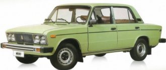
Motorcycle Features
The IZH Plante 5 motorcycle has the original name IZH 7.107. Just like the IZH 6, it belongs to the middle class of motor vehicles, designed for movement on roads with any surface. The main feature is the use of an oil pump; when refueling there is no need to add oil to the tank, as well as a contactless ignition system that operates independently of the battery.
It became possible to start a motorcycle from a pusher. To do this, you need to turn on the ignition, second gear and, when pushing the bike forward, the engine starts. True, without a battery, operation is possible only during daylight hours.
The Fifth Planet can be equipped with a cargo trailer and a passenger stroller. To reduce the clutch release effort, the bike has a clutch consisting of 7 pairs of discs. Vibration dampers are installed on the cylinder ribs. An important feature of this series is the presence of hydropneumatic suspension with disc brakes, which contributed to a smooth ride. The power is 22 horsepower, the maximum possible speed is 120 km/h. The volume of the two-stroke single-cylinder engine is 346 cm3. The power unit has good traction at low speeds.
Electrical equipment Izh Oda
Wires and fuses
Electrical equipment of cars models IZH-2717–220 and IZH-27171–020
Possible starter malfunctions, their causes and methods of elimination
Engine ignition system mod. 331
Electrical equipment of cars models IZH-2717–230 and IZH-27171–030
Possible malfunctions of the G-222 generator (372-3701), their prerequisites and methods of elimination
Model 2106 engine ignition system
Electrical equipment of cars models IZH-27171–020 and IZH-27171–030
Forced idle economizer control system (EFH)
Possible malfunctions of the EPHH control unit, their prerequisites and methods of elimination
Possible malfunctions of the EPH system, their prerequisites and methods of elimination
Possible malfunctions of the microswitch, their prerequisites and methods of elimination
Possible malfunctions of the solenoid valve, their prerequisites and methods of elimination
Headlight relay
Relay-breaker for direction indicators and hazard warning lights
Windshield wiper
Possible malfunctions of the windshield wiper, their causes and methods of elimination
Possible malfunctions of the air blower motor, their causes and methods of elimination
Motor cooling system fan motor
Possible malfunctions of the cooling system fan motor, their causes and methods of elimination
Electrically heated tailgate glass
Lighting and light signaling
Possible malfunctions of lighting and light signaling, their prerequisites and methods of elimination
Possible malfunctions of control devices, their prerequisites and methods of elimination
Cooling water thermometer sensor
Low oil pressure warning light sensor
Fuel level sensor
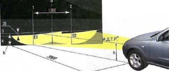
Electromechanical headlight range control
Video about “Electrical equipment” for Izh Oda
Electrical diagram of Izh 2126 / Oda Izh Oda electrical repair, super snot “Oda” IZH - 2126. Fuses, which one is responsible for the cigarette lighter? The answer is in the comments. Briefly under the video.
Contactless electronic ignition on the legend of the domestic motorcycle industry - IZH Jupiter 5
IZH motorcycles are rightfully considered legends of the domestic automotive industry. The use of these vehicles was especially important in the Soviet years, however, even today ILs are successfully used by many domestic motorists. In this article we will talk about what electronic ignition is on the IZ Jupiter 5 motorcycle and how the ignition system (IZ) is configured.
Tuned motorcycle IZH Jupiter 5
IZ Jupiter 3 uses non-contact ignition (BSZ) 1137.3734, intended for all models equipped with a 12-volt generator. The ignition coil module for Jupiter 4 or another model makes it possible to select the appropriate operating mode of the motor thanks to the serial connection of the output wires.
ELECTRICAL EQUIPMENT
The electrical equipment of the car is made according to a single-wire circuit: the negative terminals of the sources and consumers of electricity are connected to the “ground” (the body and the main units of the car, which act as the second wire). The on-board network is a constant current with a voltage of 12 V. When the engine is not running, all users are powered by a battery, and after starting the engine, by an alternating current generator with an integrated rectifier and an electric voltage regulator. When the generator is running, the battery is charged.
Most of the electronic circuits are protected by fuses installed in the mounting block. The fuse rating and the circuit it protects can be found in the tables (for mounting blocks of the old and new standard). The electric motor of the windshield wiper gearmotor is protected by an automatic reusable bimetallic fuse. Fuses are NOT installed in the ignition, starter, or battery charge circuits. Massive users (starter, headlights, cooling fan motor, etc.) are connected via electromagnetic relays.
The electrical diagram of the vehicle is given in the “Appendices”.
Source: litezona.ru
Discounts from the help desk
When you mention ACC, you can get discounts on parts and services
Auto Information Service: auto news, spare parts in Krasnoyarsk for foreign cars and Russian cars, dismantled cars, car repairs, addresses and phone numbers of companies, bulletin boards, collections of spare parts, maintenance and repair departments.
All information presented on the website is for informational purposes only and under no circumstances constitutes a public offer.
Source: autoinfo24.ru
Electrical circuits? - even a schoolboy can figure it out!
When I first encountered a schematic electrical diagram of a car, I realized that the principles of its construction and the designation of elements on it are standardized, and those elements that are present in all cars are designated the same way, regardless of the car manufacturer. It is enough to figure out once how to read such electrical diagrams, and you can easily understand what is shown on it, even if this is the first time you have seen a specific diagram from a specific car and have never even climbed under the hood of it.
Graphic designations of circuit elements may differ slightly; in addition, there are black and white and color versions. But the letter designation is the same everywhere. In addition to schematic electrical diagrams, it is useful to have diagrams that indicate the physical location (in space) on the body of various harnesses, connectors and grounding points - this will help you quickly find them. So, let's take a look at examples of such circuits, and then proceed to describe their elements.
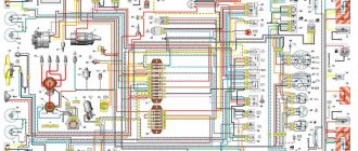
An example of a car electrical circuit diagram
The circuit diagram does not indicate the physical relative positions of the elements, but only shows how these elements are connected to each other. It is important to understand that if two elements on such a diagram are shown next to each other, on the body itself they can be in completely different places
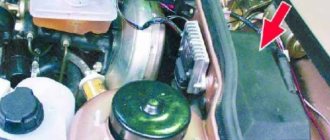
Schematic arrangement of electrical components on the body
Such a diagram carries another type of information: the routing of the cable braids and the approximate location of the connectors on the body.
Three-dimensional accurate diagram of the location of electrical components of the car
There are also diagrams that show exactly how and where the cable routes go in the car body, as well as grounding points.
Electronic circuit of the car IZH 2126
List of fuses IZH 2126 “Oda”
Blocks of both the old and the newest (with knife-shaped fuses) standard can be installed on the square. Blocks of different designs are not interchangeable.
Fuse number (current, A) Electronic circuits protected by fuses
4(16) Radiator fan relay coil. Electrical circuit of switches and electric motor of the heater
5(3) Hazard switch (in turn signal mode), turn signal switch, turn signal switch Turn signal warning lamp, turn signal warning lamps Reversing light switch, reversing lamps Tachometer Voltmeter Fuel gauge, fuel level sensor, warning lamp Fuel level Temperature indicator! cooling water Temperature sensor Control lamp and emergency oil pressure sensor Brake system emergency lamp Hydraulic brake switch Parking brake switch
6(8) Brake light switch and lamps Interior lighting
7(8) Lamps for the license plate light Control pump for turning on the side lighting Lamps for illuminating the heater and cigarette lighter levers Lamp for lighting the glove box Switch and lamps for illuminating the arrangement of devices
8(16) Horn, horn switch Radiator fan motor
9(8) Side light bulb for left headlight Side light bulb for left rear light
10(8) Side light bulb for the right headlight Side light bulb for the right rear light bulb Switch for the fog light bulbs Indicator light for the fog lights
11 (8) Switch, turn signal breaker and turn signal lamps, control pump in hazard warning mode
12(16) Cigarette lighter, socket for portable lamp
13 (8) High beam right headlight
14 (8) Left headlight high beam, high beam warning lamp
15(8) Low beam right headlight
16(8) Low beam left headlight
Electronic circuits protected by fuses (latest standard mounting block)
Fuse number (current rating A) Electronic circuits protected by fuses
F2(10A) Direction indicators and hazard warning relay (in hazard mode) Hazard warning lamp
F3(10A) Rear lights (brake lamps) Interior lamp
F4(20A) Rear window heating element Relay (contacts) for turning on the rear window heating Cigarette lighter, socket for a portable lamp
F5(20A) Horn, horn switch
F7(30A) Heater fan electric motor Windshield washer electric motor Relay (coil) for turning on the electric radiator fan Relay (winding) turning on the rear window heating Control lamp for turning on the heated rear window Glove box lighting
F10(7.5 A) Left headlight (side light)
F11(7.5 A) Right headlight (side light)
Differences from the second Planet
For many modern citizens, the information that domestic motorcycle manufacturers worked tirelessly to improve their models in an era of total shortages may come as a surprise.
Note! The fact takes place, moreover, it is supported by official documents, in particular 1970N04P16-17 - this is the outgoing number of the factory newsletter, which described the changes made.
In the photo - official materials of the Izhmash Design Bureau
The new generation motorcycle received:
- Direction indicator lights are a first in domestic practice;
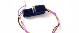
- Semiconductor relay for controlling direction indicators (installed in the headlight);
- New size of wheels and tires (3.50x18 versus previous - 3.25x19);
- New brand increased capacity battery (old one on IZH Planet 2 - ZMT-6);
- And, of course, more engine power. The power unit now developed 18 hp.
Modifications
But the creator engineers did not stop there and, having released the five-millionth car from the production line, presented a modification of the IZH Planet 3-01.
Mirror and safety arches are the distinctive features of the new modification
Among the innovations it should be noted:
- Rear passenger footrests;
- Roll bars;
- Rearview mirror;
- New steering wheel design.
For reference: The buyer paid for the changes out of his own pocket. In particular, the price for IZH Planet 3-01 was 750 rubles, the version with a stroller was 1140, and the “rural version” was even more expensive. Fortunately, care instructions were included with purchase, which made maintenance easier.
Izh 2717 electrical diagram
This section contains various electronic circuits for cars IZH 2126 ODA 2717 21261 NIKA 27171 4×4 Fabula sent by various members of our club. All diagrams are available for download in pdf and jpg formats. The dimensions of the diagrams are mainly selected for printing on A3 format.
- Izh 2126 “Ode”. Electronic connection diagram (jpg – 4.8 MB)
- Izh 2126-020 “Oda”. Electronic connection diagram (jpg – 665 KB) (pdf – 393.4 KB)
- Izh 21261 “Fabula”. Electronic connection diagram (jpg – 917 KB) (pdf – 641.5 KB)
- Izh 21261 “Fabula”. Electronic schematic diagram of connections of electrical appliances (jpg – 732 KB) (pdf – 270.4 KB)
- Izh “ODA” 2126, 2717 Electronic wiring diagram for cars manufactured before 2001. with dashboard 2141, (jpg – 3.74 MB) (pdf – 18.94 MB)
- Electrical schematic diagram of the rear wiper (jpg – 242 KB) (pdf – 104 KB)
- Electronic schematic diagram of the mounting block (jpg – 355 KB) (pdf – 196.6 KB)
Wiring diagram for turning on external lighting:
1 — side light lamps in headlights; 2 — mounting block; 3 — ignition switch; 4 — external lighting switch; 5 — side light lamps in the rear lights; b — license plate lights; 7 - signaling lamp for turning on the side light.
Electrical diagram for turning on the headlights
1 — low/high beam lamps in headlights; 2 — mounting block; 3 - relay for turning on high beam headlights; 4 — relay for turning on headlights; 5 — ignition switch; 6 — external lighting switch; 7 — headlight switch; 8 - indicator lamp for turning on high beam headlights.
Circuit diagram for switching on brake lamps and reverse lights
1 - mounting block; 2 - jumper; 3 — reversing light switch; 4 — brake light switch; 5 — ignition switch; 6 — brake light lamps; 7 — reversing lamps.
Reasons for connecting a “foreign” generator and electrical diagram
The “native” generator, originally included in the design of the IZH “Jupiter 5”, is the second serious drawback of the motorcycle. It is weak, which makes it almost impossible to drive for a long time with the lights on. The battery runs out and the vehicle loses its performance. Moreover, the problem lies not only in the generator itself, but also in the fact that the possibility of connecting additional equipment is completely excluded. Therefore, you will need a wiring diagram to replace the standard device with a more “Chinese” one.
You can choose the appropriate option either independently or with the help of specialists. If you have little understanding of the electrical circuit of a motorcycle, it is better to entrust repair and improvement work to professionals. Specialists will correctly connect all the wiring and ensure the correct operation of the contactless ignition, lock, headlights and other elements.
vote
Article rating
ELECTRICAL EQUIPMENT
The electrical equipment of the car is made according to a single-wire circuit: the negative terminals of the sources and consumers of electricity are connected to the “ground” (the body and the main units of the car, which act as the second wire). The on-board network is a constant current with a voltage of 12 V. When the engine is not running, all users are powered by a battery, and after starting the engine, by an alternating current generator with an integrated rectifier and an electric voltage regulator. When the generator is running, the battery is charged.
Most of the electronic circuits are protected by fuses installed in the mounting block. The fuse rating and the circuit it protects can be found in the tables (for mounting blocks of the old and new standard). The electric motor of the windshield wiper gearmotor is protected by an automatic reusable bimetallic fuse. Fuses are NOT installed in the ignition, starter, or battery charge circuits. Massive users (starter, headlights, cooling fan motor, etc.) are connected via electromagnetic relays.
Generator UAZ
Installation of a 90 Amp UAZ 469 generator
After the first use of the winch, the native (USSR) 40A generator stopped charging the battery. A 90 Amp generator from a steer was found in the garage. The mount is the same as on the UAZ. This generator has been sitting for 5 years and it is not known what condition it is in. If you don't put it, you won't know. A voltage regulator (hereinafter referred to as RN) from Volga (13 3702) was purchased. In order for the new generator to fit correctly into place, you need to install a pulley from the old generator on it. It was not possible to remove the pulley from the Soviet generator manually and using a screwdriver.
I bought a bearing puller and removed the pulley.
Next, we cut the wires, attach the terminals, and connect them to the LV.
Now, we install and connect the new generator.
So why did I redo the wiring for the generator, and not connect everything to the new one as it was before?
The fact is that my old generator schematically looked like this:
The new one from the 90 A bull looks a little different:
90 A generator from Bychka
Because Since we get different terminals of the brush assembly, the connection diagrams will be slightly different.
I used this connection diagram:
Scheme for connecting a generator with a two-pin output from the brushes
Result: the voltage, as expected, is 14 V. But, when the headlights are turned on, it drops to 13 V. My fault is that: 1. Used generator. 2. I left the pulley from the old generator, and it is slightly smaller in diameter, this also affects the voltage depending on the speed. 3. The idle speed of the UAZ is low compared to other cars. 4. According to experienced people, this problem (voltage drop) is observed on almost all Soviet cars, so many install running lights and drive without a neighbor during the day. I think I'll do that too.
Transfer of the generator to the top of the UAZ-469 (417 Engine) UAZ 3151
— Generator 90A BATE — 1 pc. 4300 rub. — Alternator belt Klinova 1225/10 200 rub.
The old generator stopped holding a charge, and I decided to repair it and carry it as a spare, and buy myself a more powerful one with 90A and immediately raise it higher from the future water level, so that it would live with me a little longer than the one that constantly floats in the water, yes and have some charging when you’re standing up to your knees in water... I found a corner from a friend, bought a 1225/10 belt, bought a 90A BATE generator and off I go! First, I removed the old generator, I had no problems, except that the new Volgov barrel for the snorkel was a little in the way. I marked and drilled on the corner and tried it on the engine, everything seemed to be going according to plan, then I drilled two more holes on the other side of the corner for attaching the genes and we put everything together and put it in place. I thought everything worked out, but after putting on the alternator belt, we see how the belt passes under the thermostat, and it gets in our way. We try to re-drill the holes 1 cm lower in the corner and it doesn’t give us anything - it still hurts a little. Then my friend said, this is all nonsense and we need to do it right - throw out this corner! I took a piece of cardboard and scissors and began to make a pattern for the future part, crumpled something there, bent it, and here it is - a work of art. We trace it onto the metal, and I, with a grinder in my hands, begin to shape it from a rough and ugly piece of metal into a high-quality and processed, almost factory-made part, even if you put a stamp on it for sale! As a tuning, I would add a cutout on top and, of course, paint it red, but since there was little time, we were content with what we had!