VAZ-1111 especially small class passenger cars are equipped with 12-volt electrics with a negative terminal connected to the car body. The cars were equipped with carburetor and injection power units, which had little effect on the location and purpose of the circuits. The VAZ-1111 electrical circuit, which is basic for all versions of the Oka, can be used when repairing a car of any year of assembly.
What is included in the Oka electrical circuit?
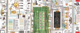
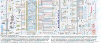
Electrical diagram of VAZ-1111 with symbols
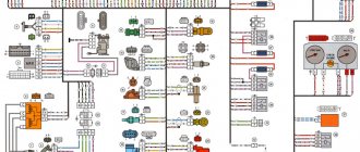
Electrical diagram of VAZ-11113 with symbols
Contactless ignition diagram indicating the main elements and connecting wires
Fuse diagram for VAZ-1111 and 11113
Common electrical faults
Download Oka schemes
Comments and Reviews
What is included in the Oka electrical circuit?
The vehicle electrical system includes the following components:
- contactless ignition system;
- ignition switch with contact group and auxiliary relays;
- alternating current generator with built-in control unit;
- an electric DC motor used to start the power unit;
- external lighting and alarm system, together with wiring and controls;
- a sound signal warning other road users;
- front and rear window cleaners and washers;
- electric heating of the glass surface on the tailgate;
- control of the air supply system through the heater;
- instrument cluster with control indicator lamps;
- A fuse block that protects circuits from excessive current (caused by a short circuit or component failure).
Voltage sources for electrical operation are:
- Battery located in the engine compartment. The device is used to start the power unit and provide electricity to consumers when the engine is not running.
- A generator driven by the crankshaft of a motor. The product is designed to replenish the battery charge and ensures the operation of the electrics while the car is moving.
Separation by purpose
By purpose, the equipment is divided into:
- Power supplies;
- Protective means;
- Controls;
- Instrumentation;
- Actuators;
Some circuit components have dual purposes. These include relays, which are both control elements and protective devices.
Power supplies
Power sources include the battery and generator. The battery powers the electricity. devices and ensures their operation when the power unit is turned off. After starting the engine, the on-board network is powered from the generator, which also ensures that the battery is recharged.
Protective components
Protective means prevent burnout of electrical appliances and electrical circuits during short circuits. The main protective elements are fuses. For convenience, all protective elements are collected in one place - the fuse box, which in Oka is located under the front panel on the driver’s side.
Controls
Control elements include all components responsible for turning on, switching and turning off electrical appliances. This category combines the ignition switch, all kinds of switches and switches. Most of these elements are located within direct reach of the driver - on the front panel, steering column. But there are switches that the driver acts on through certain components - brake light switches, a sensor for turning on the choke warning light, etc.
instrumentation
Control and measuring devices provide the driver with information about the operation of certain components and mechanisms, operational indicators - fuel level, coolant temperature, oil pressure, etc. Some types of these devices display accurate information, while others are presented in the form of warning lamps that are triggered only when an emergency occurs. malfunctions.
Related link:
Removal and repair of the cylinder head of the Oka car
Measuring instruments combine sensors installed on the required components and mechanisms, and signal elements located on the dashboard.
Actuating devices
Actuators are components that perform one or another function - they illuminate, operate components, etc. These include electric motors, lighting lamps, a sound signal, a cigarette lighter, etc.
Electrical diagram of VAZ-1111 with symbols
List of elements indicated in the diagram:
- 1 — side turn signal repeater located on the front fender;
- 2 — front direction indicator;
- 3 — head lighting device;
- 4 - electric motor used to drive the radiator cooling impeller;
- 5 — warning sound signal (horn);
- 6 - temperature sensor, which ensures that the cooling system impeller is turned on;
- 7 — motor for driving the front window washer pump;
- 8 — distribution sensor of the ignition system;
- 9 — lead-acid battery;
- 10 - electric motor for starting the engine;
- 11 — ignition system controller;
- 12 — spark plugs installed in the cylinder head;
- 13 — ignition system coil;
- 14 — alternating current generator;
- 15 — liquid temperature indicator in the cooling jacket;
- 16 - control sensor that determines emergency oil pressure in the engine;
- 17 — connector for installing a portable lamp;
- 18 — windshield wiper operation controller;
- 19 — indicator sensor of the fluid level in the hydraulic brake drive system;
- 20 — brake pedal position limit switch;
- 21 — motor for driving the trapezium wipers on the front window;
- 22 - electromagnet located in the carburetor valve;
- 23 — limit switch responsible for the operation of the reverse gear signals;
- 24 — starter controller;
- 25 — headlight control relay (low beam);
- 26 - similar unit for high beam;
- 27 — controller of direction indicators and emergency lights;
- 28 — cigarette lighter socket;
- 29 — speed switch for the heating system motor;
- 30 - additional resistor that determines the rotation speed of the heater fan impeller;
- 31 — external lighting operating mode switch;
- 32 - fuse block;
- 33 — additional protective element for fog lamps;
- 34 — rear window heating control controller;
- 35 - start relay, necessary for the operation of the cooling system fan;
- 36 — control relay for the control indicator of the position of the parking brake lever;
- 37 — control of the rear window cleaning system (together with the washer);
- 38 — glass heating operating mode switch;
- 39 — rear fog light button;
- 40 — indicator of the open starting valve in the carburetor;
- 41 — alarm control button;
- 42 — ignition switch;
- 43 — distribution relay of the ignition system;
- 44 — heating fan impeller motor;
- 45 — indicator of the amount of gasoline in the tank;
- 46 — interior lighting switch located on the central pillar;
- 47 — instrument cluster;
- 48 — front wiper control;
- 49 — turning on the windshield washer;
- 50 — horn control button;
- 51 — lever for changing the operating modes of the head lighting;
- 52 — direction indicator control lever;
- 53 — limit switch, responsible for indicating the position of the parking brake lever;
- 54 — interior lighting lamp;
- 55 — limit switch located behind the carburetor choke control button;
- 56 — motor for driving the glass washer pump on the rear door;
- 57 — stern canopy;
- 58 - fog signal, located on the rear of the car;
- 59 — registration plate illumination system;
- 60 — tailgate glass heating threads;
- 61 — stern wiper blade drive motor.
The specified colors of connecting wires correspond to the factory documentation. During repairs, many owners replace sections of the harnesses with cables with insulation of a random color. Because of this, some vehicles have difficulty identifying the wiring.
Relay block
On the left side under the instrument panel there is a block of five identical relays (90.3747-10 / 113.3747-10 / 2105-3747210-20)
p, blockquote 9,1,0,0,0 —>
Scheme
Designation
| 1 | Engine radiator fan relay |
| 2 | Low beam relay |
| 3 | High beam relay |
| 4 | Starter relay |
| 5 | Heated rear window relay |
Electrical diagram of VAZ-11113 with symbols
The electrical circuit of the VAZ-11113 does not differ significantly from the VAZ-1111. The car was equipped with a modernized version of the power unit and some components that had virtually no effect on the electrics.
Contactless ignition diagram indicating the main elements and connecting wires
Contactless ignition VAZ-11113
- 1 - control relay;
- 2 — ignition switch with contact group;
- 3 - protective fuse;
- 4 - controller;
- 5 - sensor that determines the moment of spark supply;
- 6 - common ignition coil;
- 7 - candles.
How does a switch work?
Essentially, a switch is a simple signal amplifier. It can even be compared to a Darlington assembly, which is used in microcontroller technology to convert a weak signal from an output port to the required level. The basis of this assembly is field-effect transistors operating in switch mode. An operating voltage is applied to them, a signal is sent to the control terminal, which is amplified and removed from the collector.
The ignition switch has an almost similar operating scheme. Only the signal from the Hall sensor is used. It has three outputs - control, common, plus power. When a metal plate appears in the sensor area, a current is generated, which is supplied to the input of the switch. Next, the signal is amplified and supplied to the primary winding of the coil. The entire system is powered only after the ignition is turned on (after turning the key).
Electrical diagram of SeAZ-11116
On SeAZ-11116 cars with a Europanel and a Chinese 3-cylinder engine, the electrics have undergone changes. The cars use an electronic instrument cluster, which has led to the emergence of a number of new sensors. The fuel supply system was changed, into which a fuel pump with a control relay was introduced. Big innovations appeared in the engine compartment, where a fuel injection and ignition control system began to be installed. At the same time, the main part of the wiring, the fuse and relay box was carried over unchanged from the old carburetor version.
Additional relays
Depending on the configuration and design, additional relay placement is possible.
p, blockquote 13,0,0,1,0 —>
Scheme
Purpose
- Hazard warning and direction indicator relay (494.3747 / 2105-3747010-01) - located behind the instrument cluster.
- Front wiper relay (RS-514 (2101-5205150)) - located under the upholstery, left side panel.
- Parking brake warning lamp relay (RS-492 (2101-3803150)) - located behind the instrument cluster, next to the turn signal relay (see point 1).
- Additional relay (90.3747-10 / 113.3747-10 / 2105-3747210-20).
- Ignition relay (90.3747-10 / 113.3747-10 / 2105-3747210-20) - secured with a self-tapping screw from inside the instrument panel.
Fuse diagram for VAZ-1111 and 11113
The fuse block is located at the bottom of the instrument panel on the driver's side. The unit is protected on top by a quick-release plastic cover with a spring lock. The machine uses obsolete cylindrical type fuses. A list of inserts is printed on the outside of the lid.
Fuse markings on the cover
If a fog light is installed on a VAZ-1111 or 11113, it is protected by a separate insert (nominal 8A) located on the wiring harness next to the control button.
List of fuses with a description of the protected circuits on cars with a carburetor engine:
| Number on the diagram | Denomination, A | Protected elements |
| 1 | 16 |
|
| 2 | 8 |
|
| 3 | 8 | Left side high beam and indicator lamp in the instrument cluster. |
| 4 | 8 | Starboard main beam. |
| 5 | 8 | Low beam on the left side of the car. |
| 6 | 8 | Likewise on the right side |
| 7 | 8 | Side lights on the left side (front and rear), registration plate illumination and indicator for turning on the “dimensions” (in the instrument cluster) |
| 8 | 8 | Dimensions of the starboard side, lighting system for the cigarette lighter socket and instrument cluster |
| 9 | 16 | Operation of turn signal indicators in hazard warning mode, rear window heating filaments together with the control relay |
| 10 | 16 |
|
Next to the fuse block there is a frame with five relays for the following purposes:
- turning the fan motor on and off;
- low beam activation;
- selecting high beam operating modes;
- starter engine starting systems;
- threads of electric heating of the tailgate.
External view of the relay block on the Oka car
All relays used on VAZ/SEAZ 1111 and 11113 are of the same type, which simplifies vehicle repairs in the field.
Replacing the turn signal relay is demonstrated in a video filmed by Sergey Neverov.
Diagram of the electric vacuum clutch drive (EPS)
- Gearbox lever handle with EPS forced engagement contact;
- Speed sensor;
- The electronic unit;
- Switch;
- Ignition coil;
- EPS mode switch;
- EPS warning lamp;
- Clutch cable;
- Clutch drive fork;
- Adjusting nuts;
- Vacuum chamber with electromagnet;
- Lock-nut;
- Vacuum chamber cable;
- Seal;
- Clutch lever (pedal);
- Axis;
- Adjusting nut;
- Lock-nut; S1 - Air damper position limit switch; S2 - Accelerator position limit switch.
Connection diagram of relay 602.3747 to the vehicle clutch control system
A1 - Speed sensor 351.3843; A2 — Ignition coil*; AZ - Ignition system switch*; A4 - Relay EPS 602.3747; HL1 - Indication lamp for turning on the air damper type A12-1.2*; HL2 - Electromagnet current indication lamp (EPS control lamp) type A12-1.2*; SV1 - Rechargeable battery*; L1 - Electromagnet type 12.3747; S1 — Air damper position limit switch*; S2 — Accelerator position limit switch**; S3 - Switch on the gearshift lever *; SA1 — EPS mode switch***; PR1 - Fuse 8 A*. Note:
* Standard equipment used on the Oka car. ** The contacts open at the beginning of the accelerator pedal stroke. *** Positions of the key switch SA1: 1 - EPS is off; 2 - EPS enabled; 3 — EPS is on, TDU mode is on.
Common electrical faults
Common problems with electrical equipment on VAZ-1111 and 1113:
- Failure of external lighting devices. A common cause of failure is burnt out lamp filament; the unit must be replaced. If the light bulb is intact, then there may be a defect in the electrical wiring, due to which a short circuit occurs and the fuse fails. The fuse link is replaced with an identical one; it is prohibited to use parts designed for a higher current. It is also unacceptable to install homemade jumpers (“bugs”), as this can cause a fire. If a repeated burnout occurs, it is necessary to check the circuit and eliminate the wiring fault.
- Wire breaks occur at points where the insulation is subject to bending or friction against moving surfaces. An example of such a point is the junction of the door and the body. Damaged areas must be replaced with products made of similar material with an identical cross-section.
- Oxidation of contact surfaces due to moisture or aggressive liquids (for example, battery electrolyte). It is necessary to clean the surfaces down to metal, restoring the transmission of electric current.
- Relay failure associated with burnt contacts or coil breakage. The unit cannot be repaired; it must be replaced with a new one. In the event of a rapid re-failure, the vehicle's electrical system must be checked at a car service center.
- Sudden battery discharge is due to an internal short or current leakage. In winter, a partially charged battery may lose capacity due to low air temperatures. You need to charge the battery and check the condition of the wiring. If necessary, the power source must be replaced.
- Pulsating operation of external lighting lamps with an unusually bright glow indicates a breakdown of the relay regulator on the generator. Repair requires removing the unit and replacing failed components.
- Insufficient battery charge (the warning light does not go out when the engine is running). The cause may be wear on the brushes or commutator, or insufficient tension on the drive belt. The generator needs to be repaired, since the battery charge is enough for 150-200 km during the daytime.
- Poor contact between the ends of the cylindrical fuses and the spring-loaded elements in the mounting block. It arises due to the design features of the unit. Many owners, tired of dealing with the defect, install homemade blocks for knife inserts. Usually a short section from the GAZ-3110 is used, designed for 13 seats. There are self-assembled units designed for fuses and relays.
Connecting the switch
Cases vary, and it is possible that you will have to change the wiring. Therefore, you will need to take into account the purpose of all pins on the switch plug. This will allow the connection to be made correctly, and there will be no risk of damaging it. The first pin of the switch is the output. In other words, the amplified signal is removed from it. It must be connected to the terminal of the “K” coil. The second contact is connected to ground - the negative of the battery.
All three wires from the Hall sensor go to the VAZ switch. Moreover, the signal wire is connected to the sixth terminal of the switch. The fifth is the power output (the voltage on it is stable 12 Volts). The third output of the switch is ground (minus power). The third is connected inside the block to the second. But between the fourth, which is supplied with power from the battery, and the fifth there is a constant resistance and a voltage stabilizer.
Preventive measures
The main measures to ensure reliable operation of the electrics of Oka cars:
- At least once every six months, clean the outer part of the battery case and check the electrolyte level (on serviced models). At the same time, it is necessary to recharge the battery using a special device. If the vehicle is rarely used, it is recommended to disconnect the terminals.
- When carrying out repair work, you should monitor the position of the wires, avoiding damage to the insulating layer. Wires passing near moving elements must not come into contact with them under any circumstances.
- It is not recommended to turn on devices with high current consumption (audio system, high beam headlights, etc.) with the engine off. This will cause the battery to drain faster.
- Do not use homemade elements to repair electrical circuits. All used parts and assemblies must comply with the standards laid down by the designer when developing the car.
- It is recommended to carry spare fuses, relays and lamps with you. This will allow you to make minor repairs if necessary.
- When carrying out repair work that requires the use of welding, it is necessary to disconnect the harnesses from the battery and generator. On machines equipped with an injection engine, it is recommended to disconnect the connector from the control unit.
Contactless ignition system
In total, there are three huge groups of systems - contact, contactless, microprocessor. The first is divided into two subgroups - contact and using a transistor operating in switch mode. Transistors are also used in the design of a contactless ignition system. This scheme began to be actively used in the early 80s of the last century. And it has a number of advantages, which will be discussed below. The switch circuit is simple; it can be implemented both on transistors and on a controller.
But the contactless ignition system also has many disadvantages when compared with a microprocessor one. The latter allows you to control almost all engine parameters. BSZ does not allow this; it also cannot be used normally on injection engines. The reason for the obsolescence of the contactless system lies not only in the development of electronics and the automotive industry, but also in the adoption of stringent measures to ensure the environmental friendliness of internal combustion engines. Unfortunately, only microprocessor control can reduce the amount of harmful substances in the exhaust.
Video
Recommendations from the Milin0915 channel for installing a blade fuse block on the Oka.
Colored wiring diagram for the domestic OKA car. The diagram is in high resolution, so to enlarge the picture, click on it. To eliminate errors when working with the circuit, the second version of the OKA electrical equipment circuit is shown below.
OKA car wiring diagram
1 – side turn signal 2 – front turn signal 3 – headlight 4 – cooling system fan motor 5 – sound signal 6 – fan motor activation sensor 7 – windshield washer motor 8 – spark torque sensor 9 – battery 10 – Oka starter 11 – switch 12 - spark plugs 13 - ignition coil 14 - Oka generator 15 - coolant temperature gauge sensor 16 - low oil pressure warning lamp sensor 17 - socket for portable lamp 18 - windshield wiper relay 19 - brake fluid level sensor 20 - brake signal switch 21 – windshield wiper electric motor 22 – carburetor solenoid valve 23 – reverse light switch 24 – starter relay 25 – relay for low beam headlights 26 – relay for high beam headlights 27 – hazard warning and turn signal breaker relay 28 – cigarette lighter 29 – heater fan switch 30 – additional heater motor resistor 31 – exterior lighting switch 32 – fuse box 33 – fog lamp circuit fuse 34 – rear window heating relay 35 – cooling system fan motor relay 36 – parking brake warning lamp relay 37 – rear window wiper and washer switch 38 – rear window heating switch 39 – rear fog lamp switch 40 – carburetor choke control lamp 41 – hazard warning switch 42 – ignition switch 43 – ignition relay 44 – heater fan motor 45 – level indicator sensor fuel 46 – courtesy light switch in the door pillar 47 – instrument cluster 48 – windshield wiper switch 49 – windshield washer switch 50 – horn switch 51 – headlight switch 52 – turn signal switch 53 – parking brake indicator switch 54 – courtesy lamp interior lighting 55 – switch for the warning lamp for closing the carburetor air damper 56 – rear door glass washer motor 57 – tail light 58 – rear fog lamp 59 – license plate light 60 – rear door glass heating element 61 – rear door glass wiper motor.
OKA car electrical circuit diagram - another option
1 — headlights; 2 — front direction indicators; 3 — sensor for turning on the electric fan; 4 — sound signal of the Eye; 5 — electric fan of the engine cooling system; 6 — side direction indicators; 7—sparking torque sensor; 8 — spark plugs; 9 — ignition coil; 10 — electric motor of the windshield washer pump; 11 - battery; 12 — Oka car generator; 13 — oil pressure warning lamp sensor; 14 — carburetor solenoid valve; 15 — coolant temperature sensor; 16 — reverse light switch; 17 - switch; 18 — plug socket for a portable lamp; 19 - brake fluid level sensor; 20 - starter; 21 — windshield wiper gearmotor; 22 — relay-interrupter for direction indicators and hazard warning lights; 23 — relay for turning on the high beam headlights; 24 — relay for turning on low beam headlights; 25 — starter activation relay; 26 — relay for turning on the electric fan; 27 — fuse block; 28 — relay-interrupter for the parking brake warning lamp; 29 — windshield wiper relay; 30 — rear window wiper and washer switch; 31 — rear window heating switch; 32 — rear fog lamp switch; 33 — switch for the carburetor air damper warning lamp; 34 — fog light circuit fuse; 35 — control lamp for the carburetor air damper; 36 — alarm switch; 37 — external lighting switch; 38 — relay for turning on the heated rear window; 39 — heater fan motor switch; 40 — brake light switch; 41 — cigarette lighter 42 — additional resistor for the heater fan electric motor; 43 — ignition switch relay; 44 — ignition switch; 45 - three-lever switch; 46 — interior lamp; 47 — lamp switches located in the door pillars; 48 — instrument cluster 49 — parking brake warning lamp switch; 50 — sensor for level indicator and fuel reserve; 51 — electric motor of the heater fan; 52 — rear lights; 53 — rear window wiper gearmotor; 54 — rear window heating element; 55 — license plate lights; 56 — rear fog lamp; 57 — electric motor of the rear window washer pump; A - the order of conditional numbering of the plugs in the spark-torque sensor housing; B - the order of conditional numbering of the plugs in the gear motor blocks of the windshield and rear window wipers and the windshield wiper relay breaker; B - the order of conditional numbering of plugs in the blocks of the ignition switch and three-lever switch; G - the order of conditional numbering of plugs in the blocks of the instrument cluster.
Rear window cleaner and washer
- Fuse box;
- Tailgate wiper and washer switch;
- Tailgate glass washer motor;
- Tailgate glass wiper motor;
- Tailgate glass heating element;
- Tailgate glass heating relay;
- Tailgate glass heated switch;
- Ignition switch.
What is included in the electrical circuit?
To begin with, we suggest finding out a description of the systems that the Oka electrical circuit includes:
- contactless ignition system;
- switch diagram, as well as ignition relay;
- generator device connection diagram;
- connecting the starter unit;
- lighting activation, including headlights, parking lights, fog lights, turn signals and light alarms, as well as brake lights;
- sound signal;
- glass cleaner;
- rear window heating systems;
- activation of the electric motor of the cooling system fan;
- heating system;
- control panel where all control and measuring instruments are located.
General diagram for Oka with description of elements
Of the main components of the VAZ electrical circuit, it is necessary to highlight:
- Generator. Without it, not a single car can operate. Thanks to the generator unit, power is provided to the main equipment, as well as electrical appliances while driving. In addition, when the car is moving, this device charges the battery to restore its charge wasted on powering electrical appliances and starting the engine.
- Battery. If it is discharged, normal operation of the car will also be impossible. As stated above, the battery allows you to power the main equipment when the engine is not running, and also provides a charge when it starts.
- Safety block. It contains the main relays and safety elements that protect the vehicle's electrical circuits in the event of a short circuit or power surge.
Division by function
As for functions, all electrical equipment is divided into systems that perform specific tasks:
- Take part in the operation of the engine;
- Ensure traffic safety;
- Create comfortable conditions;
There are also systems that are aimed at maintaining the functionality of the electrical circuit itself.
Systems responsible for engine operation
The ignition system takes part in the operation of the power unit and its task is to generate a spark in the engine cylinders to ignite the air-fuel mixture. The components of this system are a switch, a spark torque sensor, a coil and spark plugs. The system is turned on using the ignition switch. All of these components are connected by one circuit, the diagram of which is shown below:
The second system related to electrical equipment and working with the engine is the starting system. To start the engine, a power electric motor is used - a starter, controlled from the same ignition switch. Its scheme is as follows:
The cooling system fan is also related to the engine.
Systems responsible for safety and comfort
Electrical equipment that ensures traffic safety includes:
- Light and sound alarm (turn signals, brake lights, reversing lights, sound signal);
- Main light (headlights, PTF);
- Heaters, glass cleaners and washers;
These devices are combined into several systems. Below is the power supply diagram for only one of them - the turn signals:
Since the Oka is a budget car, there are not so many electrical appliances that create comfortable conditions for the driver. These include a stove (which includes an electric fan motor), an interior lamp and a cigarette lighter.
Note that the stove, in addition to creating convenience, also affects traffic safety - it heats the windows in winter.
Since devices responsible for traffic safety and comfort are not always in demand, they are turned off by default and are activated using switches.
Related link:
How to remove the engine from Oka
The on-board network also includes a battery recharging system, that is, a component whose task is to maintain the functionality of electrical equipment. Its connection diagram is as follows:
Common faults
All malfunctions in the wiring on the VAZ 2111 Oka can be divided into several groups:
- Failure of the device itself. For example, if we are talking about headlights, then the lamps in them may burn out. If the rear window heating system refuses to work, then the unit itself may be faulty.
- Broken electrical wiring. As a rule, this problem is more relevant for wires that are laid in places where there are moving or rubbing elements. For example, wires from door locks are laid in the doors themselves, and to connect to the fuse box they are laid in special rubber corrugations. Despite such protection, wires can also break in the corrugation.
- No contact. The lack of contact may be due to either a broken wire or oxidation of the contact; in some cases, it may simply move away from the installation socket. In case of oxidation, the problem is solved by stripping.
- The fuse or relay has blown. This happens especially often in cars where there are power surges. The fuse simply cannot withstand the power of the on-board network and fails, thus protecting the device from burnout. If your car actually has power surges, then you need to either check the on-board network yourself or contact an electrician.
- Also one of the most common malfunctions is battery discharge. Car owners usually face this problem with the onset of cold weather; in some cases, it may be due to improper maintenance (the author of the video is the Milin0915 channel).
Maintenance, repair
Of all the car’s electrical appliances, only power supplies require maintenance:
- Battery (periodic recharging using chargers, monitoring the level and density of the electrolyte);
- Generator (periodic check of drive tension, replacement of worn graphite brushes).
It is also important to monitor the condition of the wire insulation and prevent it from being damaged to avoid a short circuit. Oxidation of contacts often occurs at the wiring junctions, which can lead to failure of electrical appliances.
Most of the electrical network components are maintenance-free and must be replaced if they fail. Such elements include light bulbs, small electric motors, switches, relays, fuses, and sensors.
In the starter, generator, electric. In the heater and cooling system fan motors, mechanical breakdowns may occur - wear of bearings, bushings, brushes. All these components are repairable and it is often possible to restore their functionality by disassembling, troubleshooting and installing new parts to replace worn ones.
Prevention measures
What you need to consider to prevent problems with electrical equipment:
- If you notice voltage surges or short circuits, immediately contact an electrician or fix the problem yourself.
- Carry out regular battery maintenance, at least twice a year. During maintenance, pay attention to diagnosing the liquid level in the cans, inspect the body for damage, and also charge the battery to replenish its discharge.
- When laying wiring, all wires must be securely insulated.
- Do not turn on the appliances, radio or heater at full power if the engine is not running. This will cause the battery to drain faster.
- Never install homemade safety devices (in the form of a jumper, wire or coin) into the fuse box.
Basic Switch Elements
The switch circuit is quite simple, but making this unit yourself is pointless, since buying a ready-made version will be much easier. Installation must be carried out as competently as possible, otherwise the device will not operate correctly. In addition, when using transistors, you need to carefully select them according to their parameters, and for this you need to have high-quality measuring equipment. Unfortunately, for two identical semiconductors, the spread of characteristics can be very large. And this affects the operation of the device.
General design
Since model 37.3701 is the most common, we will consider it in the future, but almost all the information is relevant for other types of generators.
The design of the generator is standard for this type of device; the unit consists of:
- Rotor (with slip rings);
- Stator;
- Covers (front, back);
- Pulley (with impeller);
- Voltage regulator (also includes a brush holder with brushes);
- Capacitor;
- Rectifier.
The design also includes rotor bearings and tie bolts, which assemble the unit into a single unit. In general, the generator circuit is standard and does not stand out in any way.
The unit belongs to the attached equipment of the power plant; it is installed on the left in the lower part of the engine compartment on the left in front of the engine. Fastening at the bottom of the unit is carried out by bolting through lugs, and at the top - using a strip.
The generator is driven from the crankshaft via a belt drive . The Oka generator belt is V-shaped, and it drives only this unit. The drive tension is adjusted by moving the device along the adjustment bar.
Ignition settings
When setting up the ignition, you will need to do the most important thing - install the shafts according to the marks so that the gas distribution functions synchronously with the operation of the piston group. This is the first thing you should do before you start adjusting the ignition. It is worth noting that there should not be any particular difficulties during setup, especially on VAZ 2108-21099 cars. The thing is that the ignition distributor on the engines of these machines can only be installed in one position. Moreover, the ignition switch does not undergo any settings during this procedure, since it does not have any.
The distributor body rotates around its axis to make more precise adjustments. And this turns out to be enough. To accurately set the torque, you can use a simple circuit that uses a simple LED as an indicator. The Hall sensor is disconnected from the system, and positive power is supplied to its negative terminal. An LED is switched on between “+” and the signal LED, and a 2 kOhm resistance is connected in series with it to reduce the voltage. But the plus of the Hall sensor is connected to ground. Now all that remains is to slowly rotate the distributor housing. The moment when the diode lights up will be the desired one.
Disassembly
Disassembling the generator, in general, is not difficult, with the exception of one point - removing the pulley. You can fix the rotor in order to loosen the pulley fastening nut using a special tool. device An alternative removal option is to fix the pulley itself in a vice using elastic attachments (for example, a belt can be placed between the pulley and the jaws).
The general operating technology of the generator is as follows:
- Remove the pulley (using a tool or a vice);
- Disconnect the capacitor wire and dismantle the capacitor itself;
Related link:
Electrical equipment Oka
- Unscrew the regulator mount and remove it;
- Unscrew the coupling bolts;
- Use a puller to tighten the front cover;
- Remove the rotor;
- Unscrew the fasteners of the stator leads to the rectifier;
- Remove the stator;
- Unscrew the nuts securing the rectifier to the back cover;
- Remove the rectifier;
After disassembly, all that remains is to remove the front bearing, which is installed in the front cover, for which you need to unscrew the bolts holding the fastening washers together.
Having finished disassembling, we clean all parts and troubleshoot. Some types of faults can be determined visually, but for such faults as breaks and short circuits of the windings, the Oka generator needs to be checked using measuring instruments. For example, to test the regulator, you need a charger with regulated voltage.
This component is checked like this:
- We connect a charger to the output and ground of the regulator, and a 12-volt light bulb (control) to the brushes;
- We apply a voltage of 12 volts, and the lamp should light up;
- We increase the voltage to 15 V (in a working regulator the control should go out);
If the lamp does not light up at 12 V or does not go out at 15 V, the regulator is faulty and requires replacement. As for the stator windings, it is better to entrust their inspection to an experienced auto electrician.
Assembly of the unit is carried out in reverse order. In this case, special attention should be paid to the correct connection of the generator , or rather all its terminals and wires.
If an auto electrician determines that the device cannot be repaired, it will have to be replaced with a new one. And what makes the generator suitable for Oka is indicated above.