I installed a signal from a Volga car a month ago, without installing a mesh in the bumper (my readers will understand). I haven’t written before, because I’ve only now completed everything (regularly) according to my mind. I connected the signals through a relay and a 15A fuse, I know there is a sect of relayless installation, but I’m not a member of it. I won’t describe how I removed the bumper this time, for anyone who hasn’t removed it yet, I will say that there is nothing complicated about it, the main thing is to be careful and with an assistant (preferably). The signals themselves were installed on brackets made of titanium (whatever came to hand was stainless) 2 mm thick. First I cut out paper templates using a marker
I traced them on metal and with the help of a grinder and such and such a mother made them. The brackets were attached with M8x30 screws to the bumper under the bumper (I removed the standard screws). We attach the sigals to the brackets with a nut and a lock washer (included) - all the mechanical parts are done, let's move on to the electrics. We cut off the standard signal and unscrew it, solder a sealed two-pin connector onto the cut wires,
we isolate it and hide it in a corrugation (Chinese connector from Aliexpress, also sold in auto stores). We make a harness from corrugated wires.
The principle is simple (I won’t draw a diagram, but if necessary, write), we use the wires that the manufacturer intended for the signal as controls for a four-pin relay. From the positive screw (in the electrical distribution box, under the hood on the driver's side), we pull the wire to the fuse, from the fuse to the power contact of the relay, and we connect the output from the relay to signals (from the positive screw to the relay and then the signals, a stranded wire with a cross-section of 1.5 was used). The peculiarity of the electrical wiring is that it is placed in an electrical distribution box
located under the hood on the driver's side, the fuse and relay are installed in their “standard” places.
To take the positive from the screw, use an 8 mm ring terminal,
(you need 6 mm, but the area for the terminal is very large and at 6 mm, the crimp of the terminal would fall under the clamping nut - there are elongated ring terminals, I looked for it and couldn’t find it). For fuse and relay contacts I used 4.8 mm Lyra contacts, they
They are standard and installed in blocks (I ordered terminal 505 in the online store). I crimped the terminals with a crimper purchased in China on aliexpress, profile SN-48B,
squeezes quite well. I used the empty sockets of the standard pads for the relay and fuse (they were just empty, I don’t know how you have them, comfort MM equipment). Now the only difference from the factory version of the electrics is the VAZ relay (Vesta has its own imported ones). I inserted the bus into the electrical distribution box from the headlight side, there is
a place for the wiring entry, covered with a plug. The contacts on the signals themselves are ordinary father - mother, I used two mothers. I don’t honk often myself, but I’ve already had to “honk” the horn a couple of times – quite decently.
Price tag: 1,000 ₽ Mileage: 6500 km
The signal on the Lada Vesta does not work
According to traffic regulations, it is prohibited to operate a vehicle with a non-functioning sound signal. It serves to prevent emergency situations on the road when road users, for one reason or another, do not see each other. Therefore, a sudden failure of this device can play a cruel joke on the car owner. If such a malfunction is detected, do not put off repairing the horn for a long time. We will tell you about the main reasons for the breakdown, most of which you can handle on your own.
Power unit in the engine compartment
The mounting block itself is located near the battery (shown in the photo below). All electrical circuits in it are reliably protected from moisture and dust using a sealed cover equipped with special latches. This adds a little comfort when operating the car.
To open the specified cover, you need to press the two latches along the edges, which are shown by arrows in the photo below.
After the block is opened, many fuses and executive relays are revealed. To avoid confusion, we numbered them all in the photo below and added a description to each element in Table 1.
The circuits that the fuses protect are shown in Table 1.
In some car modifications, the horn is protected by fuse F78 instead of F73. And food is extra. equipment in the trunk is protected by fuse F55.
The relays that are located in this block are also summarized in Table 2:
Fuse burned out
Many faults associated with the electrical equipment of a car can be eliminated by replacing blown fuses. Therefore, first of all, you should open the mounting block, which is located in the engine compartment, and find the 10A fuse F73 there, see figure:
When inspecting the protective element, pay attention to the integrity of the thread and the presence of signs of burnout. If the element is burnt out, replace it with a similar one. But it is worth noting that fuses do not simply fail; there may have been a voltage overload in the circuit or a short circuit. If the situation repeats after replacement, it is better to contact an experienced electrician.
How to check the antenna's performance
The only way to make sure it's working is to turn on the radio and evaluate the sound quality:
- Switch the radio to tuner mode.
- Search for radio stations. A working antenna should find several stations in the city and 1-2 on the highway.
- The stations found in the city in open areas should sound without interference or extraneous noise. Interference is allowed outside the city, in tunnels and underground parking lots.
If the antenna does not find the necessary radio stations, and those found sound with a huge amount of interference and are inaudible, then the antenna can be considered inoperable.
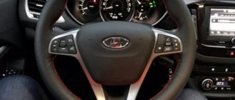
Steering column contacts
To ensure that the horn works at any steering wheel position, the designers came up with a special contact group. It is located under the steering column cover, so you will have to unscrew a few screws and remove plastic parts. There you will find a metal ring to which contacts on springs are pressed. You should make sure that they fit securely and do not show signs of oxidation. If you find a gap between them, then you need to loosen the contacts and move them towards the ring. After this, be sure to securely fasten the mounting bolts. Oxidized contacts should be cleaned.
Wiring is not ok
Have you checked all the elements in the chain, but there is still no sound? This means that the problem lies in the car's electrical wiring. At this stage, you will have to stock up on a tester to “check” the circuits. You need to make sure that there is voltage at the signal button, for which you will have to open the steering wheel cover. If your car does not have airbags, then there will be no problems, but if they are present, the task will become much more complicated. Therefore, in such a situation, it is better to contact a car service so as not to accidentally activate the “airbag”.
What malfunctions can occur in the Vesta antenna
Types of faults:
- Interference and noise. Can be caused by various devices connected to the cigarette lighter. It could be a low-quality video recorder or radar detector. In addition, spark plugs can also cause interference if they are chosen incorrectly. Only original spare parts and accessories should be used.
- Poor soldering of contacts. Unfortunately, the quality of spare parts and components leaves much to be desired, so an accidentally unsoldered wire or oxidation of the entire board is a normal phenomenon. Fortunately, the dealer is loyal to his customers and is ready to replace these items under warranty.
Before repairing or replacing the antenna yourself, it is recommended to first verify that the antenna is not working.
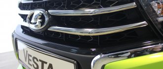
Installing “Volgov” signals on Lada Vesta, is it worth the bother and what you need to know
Vesta has a fairly conventional sound signal from the factory, although this is an integral safety attribute. Let me clarify right away that I don’t prefer to honk at everyone, I only use the signal in situations where it can prevent an accident; for other cases, high beams are quite sufficient.
However, how to prevent an accident with such a sound signal, because you need to take into account that there are cars with good sound insulation or with good music, or both. I remember that many of my friends installed pneumatic sound signals, of course they sounded good, but still it’s not something, it looks too massive + questions may arise when undergoing maintenance. In order to do everything neatly, it was decided to follow the path trodden by many - to install the so-called Volgov signals.
Before buying, it is important to know the following information - there are at least two modifications that differ in sound, as well as price, weight and dimensions. The first have numbers 22.3721/221.3721 low and high tone, respectively, the second S302/S303D.
In terms of sound, many people like the latter more, they sound somehow more mature and smoother, at the same time louder, but you need to take into account that they are noticeably larger in size. These signals are produced by two companies - SOATE and LETS.
It is better to buy in trusted and large stores for spare parts for VAZ, GAZ, PAZ, as there are many counterfeits. The original signals must bear GOST, the Quality Control Department stamp, as well as bolts for a slotted screwdriver.
Mounting block Lada Vesta in the car interior
The mounting block is located in a familiar place - near the driver’s left foot. To access the relays and fuses:
- turn the plastic handles (3 pieces) holding the unit cover from below;
- remove the lock on the upper right side of the cover;
- Pull the bottom of the cover, disconnect its upper holders to the instrument panel and remove the unit cover.
Fuse diagram (Fuse, Rating, Circuit, Purpose, Fuse type)
- F1 15A K15R Windshield washer mini
- F2 30A *1 /5A *2 K15R Left steering column switch (not luxury/luxury) mini
- F3 10A *1 Left high beam headlight (not luxury) mini
- F4 30A *1 /5A *2 K30S Left steering column switch (not luxury/lux) mini
- F5 15A K15R Heated seats mini
- F6 7.5A *1 K30S Right side lights mini
- F7 10A *1 K30S Left side lights mini
- F8 5A *1 K30S Rear fog lights mini
- F9 3A Direction indicator (turn signals) in the right mini mirror
- F10 5A K15S AMT mini robotic gearbox selector
- F11 10A *1 Left low beam headlight (not luxury) mini
- F12 15A K30S BCM controller (turn signals) mini
- F13 10A K30S BCM controller (own power supply) mini
- F14 10A K30S Mini brake pedal switch off
- F15 5A BTP Power supply for D&O (rain and light sensor), mini headlight range control
- F16 5A BTP Mini brake pedal switch off
- F17 5A BTP Lighting (canopy) for the glove box, trunk, thresholds mini
- F18 3A Direction indicator (turn signals) in the left mini mirror
- F19 10A *1 Right low beam headlight (not luxury) mini
- F20 5A Heated exterior mirrors mini
- F21 15A K15S BU SNPB mini
- F22 5A K15S Gearbox (instrument cluster) mini
- F23 5A K30S Gearbox (instrument cluster) mini
- F24 5A ACC ERA GLONASS, radio mini
- F25 5A VTR Controller ESP9.1 mini
- F26 15A K30S Power supply for mini fuel pump module
- F27 5A K15S Power supply for parking sensors mini
- F28 5A K15S EURU controller (electric power steering) mini
- F29 10A *1 /5A *2 K30S Power supply for mini trailer lighting
- F30 5A K15S Controller ERA GLONASS mini
- F31 5A K30S Controller ERA GLONASS mini
- F32 10A K15S Bus power supply K15M (engine compartment) mini
- F33 5A BTP Window control mini
- F34 5A VTR Power supply for steering angle sensor, mini steering wheel button block
- F35 5A BTP Switch block in the driver's door mini
- F36 15A K30S Radio, mini diagnostic connector
- F37 7.5A K30S Stop lamps right mini
- F38 7.5A K30S Stop lamps left mini
- F39 10A *1 K15R DRL (daytime running lights) not luxury mini
- F40 10A *1 K15R High beam headlight right (not luxury) mini
- F41 20A ACC 12V socket (power supply for additional devices), cigarette lighter JCase
- F42 20A K30S BCM controller (BTP bus power supply) JCase
- F43 20A K30S BCM controller (door locks) JCase
- F44 30A K30S Electric windows (ESP) JCase
- F45 30A K30S Interior heater fan (heater) JCase
- F46 30A *1 K15R Power supply for windshield wipers JCase
- F47 25A *2 K30S EMM controller (PDS, LBS, LGO)
- F48 30A *2 K30S EMM controller (windshield wiper)
- F49 25A *2 K30S EMM controller (PTF, ZPTO, license plate)
- F50 25A *1 K30S EMM controller (LDS, PBS, PGO)
Replacing the standard sound signal on a Lada Vesta
Replacing the sound signal on a Lada Vesta is a simple procedure that any owner should be able to perform. After all, driving without a properly working horn is a priori unsafe, and taking a car to a service station due to such a breakdown is an unreasonably large amount of time. However, replacement in the event of a malfunction is not the only need. Many people are simply not satisfied with the volume or tone of the sound signal, and they replace the standard Vesta components with alternative ones. Therefore, both of these paths need to be considered in more detail.
Pneumatic signal
Initially, an electromagnetic horn is installed in the car. Such pipes consist of an electromagnet, a membrane and a core. The sound occurs when the core rod presses on the membrane. This type of horn is most often chosen by manufacturers: they have a simple design. They are divided into:
- Horns. Average sound quality. Outwardly they resemble a forge.
- Snails. Installed with the pipe facing forward. The design is not comfortable for installation; it is used in the production of Lada Vesta cars.
- Disks. Occupies minimal space. Easy to install.
- Pneumatic horns are louder than electromagnetic ones. Their volume reaches one hundred twenty-five decibels. The tonality of the pipe covers more frequencies. In order for the pneumatic signal to work stably, you will need a powerful compressor.
- Klaxons can consist of a large number of horns: up to five pieces. A programmable relay provides detailed melody customization. The resulting tone will be unique in its content.
- The music relay is used for entertainment vehicles only. Installing such a horn for driving around the city is prohibited by Russian law.
New Lada: Roof rack for Lada Vesta: review of prices and manufacturers
Replacing the standard sound signal in case of breakdown
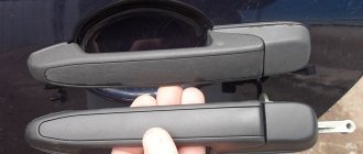
First you need to prepare the car for work by putting the parking brake on and turning off the ignition. Then you need to lift the hood and, armed with a “10” key, disconnect the negative terminal from the battery. Then you should dismantle the front bumper, which is best done with an assistant, so as not to damage the paintwork on the bumper itself and on the wings of Vesta.
The figure shows the mounting location of the Vesta signal, its plug and the signal itself.
Once this is completed, all that remains is to disconnect the plug with the wires from the signal horn. Then you can dismantle the signal itself, the bracket of which is attached to the body with one nut. For dismantling you will need an extension, a wrench and a 13mm socket.
Removing and installing the front bumper requires an assistant.
Assembly is carried out in the reverse order - you need to secure the signal, inspect its operation, install the bumper with an assistant and tighten the terminal on the Vesta battery.
How to install a Volga signal
Remove the front bumper (instructions for XRAY, Vesta, Grant, Priora, Kalina, Largus). If it was decided not to remove the standard sound signal (if necessary, you can return to the initial version), then we are looking for a suitable place to install signals from the Volga. Most often they are placed on the front bumper amplifier (on standard mounting bolts), behind the radiator grille or under the headlights on brackets.
Alternative options
In this case, the possibilities are limited solely by the imagination of the Vesta owner. Most often, sound signals from the Volga are installed on the Lada, since their sound is much louder. But there are other ways. The most common options for such “modernization” are:
- installation of signals from the Volga - in this case, different installation methods are possible (with connecting a relay in the cabin or under the hood)
— installation of other signals;
— installation of a signal with an integrated compressor;
— a combination of signal and high beam.
Setting other signals is just one of many options.
Installation of signals from Volga
It involves not only installing “shells” directly on Vesta, but also various options for connecting them. It is worth remembering that the sound signal from the Volga can be either old or new. However, they have no differences, except for a slight difference in tonality:
— sound signals Volga-3110 (22.3721/221.3721) – low and high tone;
- sound signals Volga, RAF S302/303D - low and high tone.
Sound pressure – 105-118 dB.
The signal from the Volga is perfect for the Lada Vesta.
It is necessary to take into account that simply replacing the signals on Vesta will not work, because their current consumption is different. For Vesta this figure is 5A (passport data), although in reality it usually does not exceed 3.5A. Signals from the Volga consume 8A each, which gives a total of 16A. Therefore, for their installation it is necessary to use a 4-pin type relay. In particular, you can use relay 904.3747-10.
In addition, on Vesta, only one plug is supplied to the factory signal - “Plus” is permanent, since it supplies power to the fan, and “Minus” comes from the button on the steering wheel. Regarding the Volga signals, they only need “Plus”, because “Minus” goes directly through the metal mount to the body.
This mounting option will lead to vibration and ringing during signal operation. Brackets must be used.
It is also necessary to take into account the dimensions of the sound signals - the Volgov ones are larger than the standard ones on Vesta. Therefore, installation in factory locations is excluded. In addition, it is not advisable to mount them directly to the body, as this will lead to vibration, and the sound of resonating metal will be mixed with the horn. So the best solution would be to use a bracket. The advantage of this option is its low cost - a set of “Volgov” signals will cost about 1,000 rubles.
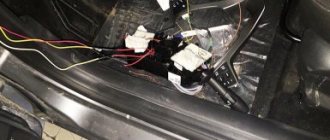
Installation of relays in the interior of Lada Vesta
This is done directly in the fuse box. To carry out the work you will need the following components:
— sound signals from the Volga;
— 4-pin type relay;
— terminals – wide (6 units) and narrow (1 unit).
For installation, it is best to use the free space in the fuse box, to which the wires from the contact relay, which is responsible for activating the signal on the steering wheel, are transferred. In the place that has become vacant, a wire from relay contact “87” is placed. Next, you will need to remove the wire from the 13th contact block and insert it into the 13th connector “87” of the relay contact.
Connection diagram for Volga signals on Lada Vesta.
To supply “Plus”, you will need to feed the wire to relay contact “30” from connector “Ш5-6”, using a jumper of contact “86”. In this case, you will have to insulate the wire in red-white or black-white color, since “Plus” always goes to it.
Recommendations
Comments 39
The lyres fit into the mounting sockets under the contacts - in the empty spaces where you want to install a relay or fuse. I'll draw a diagram later.
The relay has 4 contacts, divided into two pairs. The first pair is “low-current” - for closing and opening the relay. We connect the two wires that went to the signal (pins 85 and 86) in any order. The second pair is power, which will supply current to the signals. The wire from the ring terminal (with +) goes to the fuse contact (4.8 pin is inserted), from the fuse (4.8 pin is inserted) to the relay (4.8 pin is inserted) - any contact for relay 30 or 87, and from the remaining contact to the signal. The principle is that the wires are connected in pairs, two from the previous signal control the relay (85 and 86 on the relay). And the power wire from + to the fuse, from the fuse to the relay (let's say 30), and from the remaining (let's say 87) contact to the signal.
From the signal relay - wires to the relay control, plus from the red screw contact (on the right). The main principle.
I just don’t understand how the standard signal works without an additional relay and fuse? And why can’t you connect the Volgov signal to the standard translation and that’s it? The standard wire already has a plus. Why put a separate plus in the fuse box? Why do we need dances with a tambourine, relays, fuses, additional wiring, etc.?
You can connect it to the standard one, just replace the fuse. But the Volgo signal is controlled by one plus, and the minus is taken from the body, and there are two Volgo signals, when the standard one is one. Since it’s a hell of a hassle with the wiring for two signals, the decision was to make it as standard, and the cross-section of the wire for the Volga signals needs to be thicker, otherwise the sound might not be as bassy. For myself, I decided not to check the car’s electrical system to see if it will hold up or not, but to make sure it works.