Before directly connecting and connecting the signaling system, you should first find out how the lock itself works. After this, find the access points that are shown in the instructions on the transport. Alarms are mostly universal. They are installed on turbocharged, diesel or gasoline Niva Chevrolet engines.
Further actions:
- Before installation, you need to remove the protective structure from the steering wheel , remove five self-tapping screws with two screws. Then unscrew the panel screws that cover the mounting block and pull out the block.
- Remove the instrument panel trim and remove all screws. Unfasten the dashboard.
- a siren with a temperature sensor and a hood limit switch in the car engine compartment.
- Connect the antenna unit in the upper corner of the windshield. Place the LED type indicator on the left pillar.
- Attach the shock sensor to the steering wheel bracket , and place the service button in a hidden but easy to access place.
Installing an alarm system on Niva 21214 with your own hands
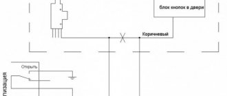
at the door limit switch
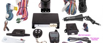
Components of any alarm system
Siren
mounted in the engine compartment.
The standard location is under the spare tire, on the original M6 bolts welded into the left wing mudguard. The service life is almost unlimited (if properly installed in the engine compartment). ALER: On the previous Nivka, the siren was located under the spare tire; there was only one longitudinal crossbar for it (the current one also has a transverse one).
Several times, while putting the spare wheel in place, I hit the siren hard, in the end I completely broke it, and I had to glue the case back together. On the current Nivka, this is taken into account: the siren is also on the left wing, but is shifted forward, closer to the radiator. Autonomous siren
according to unofficial statistics, it gives the owner an extra 6 seconds (in case of theft). Costs more than a regular siren. The service life usually does not exceed 2-3 years.
Trunk limit switch
mounted in the trunk - see Trunk lighting from ALK214 and from Alvi.
Central alarm unit
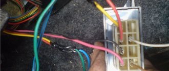
It is usually hidden behind the trim on the left at the driver’s feet, on the right at the passenger’s feet, or on the left in the pocket behind the driver’s back (for VAZ 21213, for VAZ 2121 too, but you need to remove the entire left rear panel). Installation will take more time, but there is a cable for the rear lights (this cable has blue and blue/black turns, as well as a yellow/blue ignition wire. Before installing the central alarm unit, it is more convenient to immediately extend all the necessary wires after you have decided on the locations their connections.It must be taken into account that during operation, you may have to pull the alarm unit out into the light of day, so that the wires near the unit should not be too short.
Electric door locking drives
mounted in doors. An important point is the wires between the body and the door. They often install adapter rubber tubes for wires from the VAZ-2106 and pull them through them. Although you can get by with just a black cord in double insulation, preferably flat. The latter method is less labor-intensive and accessible even to an untrained grower. On my car, there is a tube with 2106 in one door, and just a black cord in the other. I made it specifically for testing. All wires have been intact for 6 years. About how to properly mount electrical. drive in the door, can often be read on the lock packaging. If not, an article with recommendations will be posted later. Remember: before starting installation, make sure that the drive, and especially its rod and clamp, should not interfere with the lowering of the window. Also pay attention to the fact that after closing the casing, the clamp with screws does not catch on it. If after installation el. drive, you can easily lower and raise the internal door lock/unlock button - everything will work well. If you feel additional resistance when locking and unlocking the door by hand, then your email. the drive will not be able to work normally, and no stories about reinforced electric drives. drive (with a force of 10 kG) will not help you. Always, with very rare exceptions associated with mechanical wear of the door lock itself, it is possible to achieve normal operation of the centralized locking system. A popular option is to eliminate the spring in the lock itself; its role will be played by the electronics. lock drive). If the door lock itself is difficult to operate, then you can lubricate it with a lubricant like LIQUI MOLY MoS2 Rostlo"ser.
There are two types of control commands in the car: (+) command and (-) command: (+) command - there is + 12 V in this wire, the indicator light lights up if you pierce the wire with its tip (which you need to find), and the clamp "Crocodile" sits on the body of the car. (-) command - “ground”, “minus” battery, car body.
To determine commands and search for the necessary wires, it is convenient to use a probe, which can be easily made from a sharpened pin (knitting needle) covered with insulation, a 12 V light bulb attached to it, and a wire from the other terminal of the light bulb with an alligator clip at the other end.
When asked why the car wouldn’t start, a colleague at the cafe gave an absolutely comprehensive answer: “Either there’s nothing to burn, or there’s nothing to set fire to.” We will try to consider the first part - or there is nothing to burn - in a separate section. The purpose of this article is to tell you how to block the engine from unauthorized starting.
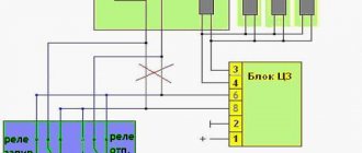
Typically, the car alarm kit includes a Saturn SCB-1-M-1240 relay or its equivalent rated at 40 A, 12 V. It is a fairly reliable relay, but the plastic ear for its fastening often breaks off. For domestic cars, you can successfully use a conventional 5-leg relay of type: 90.3747 (the location of the contacts is shown in the figure) at 20/30 A, 12 V. It is much easier to disguise it among the rest of the car’s relays.
Similar 5-leg relays type 90.3747 are usually used to control electric central locking drives.
Our task is to block the ignition circuits. Unfortunately, we must admit that the classic Niva 2121 (1.6 with a contact ignition system) can be very poorly protected precisely because of the simplicity of its ignition system. The only option for enhancing protection, i.e. increasing the theft time, is to install mechanical locks on the hood.
Purpose of the mounting block
The Chevrolet Niva mounting block combines a fuse and relay panel. To get to it, you need to unscrew the screws securing the cover under the steering column, and then pull this cover towards you. The purpose of the mounting block elements depends on the year of manufacture of a particular model. In 2009, the Chevrolet Niva underwent restyling, therefore, along with other changes, the functions of the protective devices also changed.
Fuse box before 2009
In 2009, changes were made not so much to the appearance of the panel as to the purpose of the fuses. In models produced before restyling, the relative arrangement of all electrical elements was as follows:
Each protective device ensures the integrity of a separate circuit consisting of one or more consumers.
| Fuse |
(current strength, A)
Fuse box after 2009
Since 2009, the appearance of the mounting block and the relative position of all its components on it have changed. The appearance of the relays and their purpose have changed.
The purpose of the protective elements installed in the same position has also changed.
| Protected Circuits | |
| F1 (5 A) | Backlight lamps. Trunk light. Engine compartment lamp. License plate lamps. Front marker lamps |
| F2 (7.5 A) | Low beam lamp (left headlight). Electric headlight corrector. Corrector motor gearbox |
| F3 (10 A) | High beam lamp (left headlight) |
| F4 (10 A) | Left fog lamp |
| F5 (30 A) | Power window relay. Electric windows |
| F6 (15 A) | Electric door lock control unit |
| F7 (20 A) | Cigarette lighter. Horn relay. Sound signal |
| F8 (20 A) | Rear window heating relay (contacts). Rear window heating element |
| F9 (20 A) | Glove box lighting lamp. Windshield wiper relay. Windshield wiper switch. Windshield wiper motor. Headlight wiper relay (contacts). Electric motors for headlight cleaners. Headlight washer motor |
| F10 | Reserve |
| F11 (5 A) | Rear position lamp. Instrument lighting control |
| F12 (7.5 A) | Low beam lamp (right headlight). Corrector motor gearbox (right headlight) |
| F13 (10 A) | High beam lamp (right headlight) |
| F14 (10 A) | Right fog lamp |
| F15 (20 A) | Exterior mirror control unit. Exterior mirror control motors |
| F16 (10 A) | Relay-breaker for direction indicators and hazard warning lights (in hazard warning mode) |
| F17 (7.5 A) | Individual lighting lamp. Immobilizer warning lamp. Brake light bulbs. Additional brake signal. Interior lighting |
| F18 (25 A) | Reversing lamps. Electric heater fan. Windshield washer motor. Rear window heating relay (winding). Rear window wiper relay. Rear window wiper motor. Rear window washer motor. Door lock control unit |
| F19 (10 A) | Relay-breaker for direction indicators and hazard warning lights (in direction indication mode). Devices. Differential lock indicator lamp |
| F20 | Rear fog lights |
| Fuse (current, A) | Protected Circuits |
| F1 (5 A) | License plate lights, side light lamps in the left headlight and left rear light, engine compartment lamp, side light indicator lamp |
| F2 (7.5 A) | Low beam lamp (left headlight) |
| F3 (10 A) | High beam lamp (left headlight), high beam indicator lamp |
| F4 (10 A) | Left fog lamp |
| F5 (30 A) | Power window relay, front power windows |
| F6 (15 A) | Cigarette lighter |
| F7 (20 A) | Horn Relay, Horn, Trunk Lamp |
| F8 (25 A) | Heated tailgate glass element, heated tailgate glass relay, heated outside rear view mirror elements |
| F9 (20 A) | Heated tailgate switch, windshield wiper relay, windshield wiper motor, windshield washer pump, right steering column switch, glove compartment lamp, reverse lamps |
| F10 (20 A) | Remote control unit for electrical accessories (door locking) |
| F11 (5 A) | Side light lamps in the right headlight and right rear lamp, instrument lighting brightness control |
| F12 (7.5 A) | Low beam lamp (right headlight), gear motors for headlight beam control |
| F13 (10 A) | High beam lamp (right headlight) |
| F14 (10 A) | Right fog lamp |
| F15 (20 A) | Outside mirror control unit, electric outside rear view mirrors, heated seat control unit |
| F16 (10 A) | Relay-breaker for direction indicators and hazard warning lights (in hazard warning mode) |
| F17 (7.5 A) | Interior lamps, anti-theft system status warning lamp, brake lights, additional brake light |
| F18 (25 A) | Heater fan |
| F19 (10 A) | Relay-interrupter for direction indicators and hazard warning lights (in turn signal mode), instrument cluster (except for engine management system malfunction warning lamp), starter relay |
| F20 (7.5 A) | Fog lamps in the rear lights, anti-theft control unit, buzzer |
Niva 2121, 2131 Alarm installation
Connection points for Niva 2121
We install the StarLine A93 alarm system with engine start
1. To access the ignition switch, remove the lower part of the steering casing. To do this, first unscrew the four screws and one self-tapping screw from the bottom, and then remove the lower part.
2. Remove the instrument panel. To do this, you need to unscrew the 2 screws of the decorative trim of the instrument panel and remove it, then unscrew the two nuts securing the instrument panel and remove it, disconnecting the connectors.
3. Install an antenna with a built-in shock and tilt sensor on the windshield, an LED on the left pillar. Install the service button in any convenient place.
4. Install a siren under the hood (attach it with two self-tapping screws), a temperature sensor (using clamps) and a limit switch. Route the wires to the passenger compartment through the standard seal on the left side of the engine shield
5. Attach the StarLine A93 unit to the instrument panel.
6. Connect the StarLine A93 ground behind the instrument panel to the standard location.
7. In the harness of the white connector of the instrument panel, connect the parking brake limit switch and engine operation control (tachometer).
8. In the white connector harness behind the instrument panel, connect the turn signal control
9. Install two-wire electric drives in the doors and connect according to Scheme 2.
10. In the harness of the gray connector to the left of the steering column, connect the common wire of the door switches.
11. In the ignition switch connector harness, connect the power circuits for starting the engine, power supply for the security and telematics complex and the power starting module. Connect the yellow wire of the X4 connector of the security and telematics complex to the ignition power wire (blue). It is recommended to make these connections using soldering
12. Check the functionality of the security and telematics complex. Reassemble the interior in reverse order
Comments and reviews
Or we put the ring included in the lineman’s kit onto the lock and connect it with a standard connector. We connect the thick yellow signal wire to the ignition wire from the lock.
We break both starter wires under the lock. We connect the thin black and yellow signal wire from the side of the lock. Thick black and yellow - further into the bundle. We break the black wire of the ground ring in accordance with the choice of manual transmission. We make settings in the signaling: Duration of cranking by the starter - 3.6 seconds.
Engine control - tachometer. Specifically for the shnivy, you can also set the engine type to diesel with a starter delay of 6 seconds.
StarLine A93 + i95 and Chevy Niva
So that the pump has time to pump up pressure in the fuel system. This is all that is written in the instructions. But autorun will not work like that. Tue Feb 01, Constant plus If the alarm system has auto start, then I take this plus from the battery terminal. If it’s a simple alarm, then the thick pink wire is on Ш3.
Preparing to connect the alarm
Before directly connecting and connecting the signaling system, you should first find out how the lock itself works. After this, find the access points that are shown in the instructions on the transport. Alarms are mostly universal. They are installed on turbocharged, diesel or gasoline Niva Chevrolet engines.
Further actions:
- Before installation, you need to remove the protective structure from the steering wheel , remove five self-tapping screws with two screws. Then unscrew the panel screws that cover the mounting block and pull out the block.
- Remove the instrument panel trim and remove all screws. Unfasten the dashboard.
- a siren with a temperature sensor and a hood limit switch in the car engine compartment.
- Connect the antenna unit in the upper corner of the windshield. Place the LED type indicator on the left pillar.
- Attach the shock sensor to the steering wheel bracket , and place the service button in a hidden but easy to access place.
Installation features
All installation and connection work is divided into two stages . The alarm system control unit is connected to the shock sensor and LED so that it starts working correctly. Since the terminals of the security system contacts are the most labor-intensive and critical part of the work, it is necessary to gradually connect the conductors to the relay of the battery terminal battery.
Note! You also need to carefully connect the conductors to the turn signals, siren, trunk release buttons, brake system limit switch, ignition switch, door limit switch.
Connection points for car alarms on Niva Chevrolet
On the 2013 Niva Chevrolet car alarm , the ignition switch is blue and black, the starter is red, the turn signal is blue, blue and red, the handbrake is brown, the tachometer is black.
On the Niva Chevrolet car alarm, the door and trunk limit switches are white or black diode, the turn signal is blue in the driver's threshold. The central lock is blue for opening and brown for closing. Served minus.
Connection points for car alarms on Niva Chevrolet 2017 , all limit switches on the immobilizer unit. The central locking unit cannot be disassembled and soldered in place. Turn - blue and black. Motor control - one positive wire.
Detailed connection instructions
To install an alarm, you need to take electrical tape, a screwdriver, a protective LED, a driver's door activator, a soldering iron, rosin, solder and an alarm. It is important not to start connecting without familiarizing yourself with the theoretical material.
It is worth understanding that the installation methods of signaling may be different. After collecting materials and understanding the introductory information, you can begin to install an alarm :
- Shock sensor connection stage . The sensor must be connected to a three-pin switch connector located on the right side at the bottom of the block housing. Connect the LED indicator connector on the left of the alarm block housing. Connect the button to the contact located at the bottom of the housing alarm unit.
- Central locking . Connect the yellow wire and the yellow wire with a black stripe with a black stripe to the battery that has a positive terminal. Connect the orange wire and the orange wire with a black stripe to the battery with the negative terminal. Connect the remaining white wires to the central ignition switch.
- Connecting an alarm with ten wires of different colors.
Response to deviations
It happens that the standard Niva alarm is not activated even if the door locks are closed. In this case, you should open the safety switch “3” using the key “2”. The switch itself is located in a glove-type box.
It also happens that the hazard warning lights do not work when turned on. This may indicate that the trunk lid, hood or one of the doors is open, in parallel with the perimeter control function being disabled. In this case, you should close the doors and trunk lid tightly. After this, the emergency lights will flash, indicating the activation of the perimeter control mode.
When the battery is completely discharged, the standard Chevrolet alarm system is characterized by continuous operation for no more than five weeks.
Connection steps
Step-by-step instruction:
- the topmost yellow conductor to the contacts of the relay power coil. Insert the closed electrical contacts of the relay into the place where the power supply to the ignition coil is interrupted. Cut the cable connecting the relay power coil to the ignition switch. Connect the ends that were formed after the cut to several relay contacts. Then connect the wire that comes from the ignition switch to the wire of the coil relay.
- Connect the black wire It is important to disconnect the battery before connecting to avoid damaging the electrical wiring of the vehicle.
- Connect the brown wires
- Connect the pink conductor Black connect to the housing or to the battery negative pole.
- the red wire to the positive terminal. The yellow and black central locking wires should be connected to it.
- the green conductors or the negatives of the trunk opening to the power coil with an additional relay.
- the white conductor to the ignition switch, the contact that closes when turning the key and the supply voltage, and the blue conductor to the door limit switch.
Note! Connect the orange conductor elements to the brake pedal switch.
Basic malfunctions and problems that you may encounter when connecting yourself
The connection process is quite labor-intensive. A problem may arise with choosing a large variety of models, installing a car alarm system to the central locking system and choosing an installation scheme. When choosing an alarm system, buyers should consider the functional features of the system.
To solve the problem with installing an alarm, it is necessary to determine the connecting points of the security mechanism, starting from the model and location of such an element as the central unit of the system.
The problem of choosing an installation scheme can be solved using original car alarm circuits.
Problems can arise due to careless or incorrect installation of the control alarm unit , installation of inappropriate security system firmware, incorrect placement of the shock sensor, poor-quality connection to the car wiring, incorrect placement of the key chip during autostart.
Due to poor installation, after some time, twisted or poorly insulated wires will begin to oxidize , which will lead to a break in the electrical circuit. Not only the security system, but also the electrical wiring system of the car will fail. If the alarm is set incorrectly, this will lead to frequent false alarms, which will interfere with the operation of the siren.
Where to begin
The installation procedure for Tomahawk alarm models TW 9010, TZ 9020, 4000, 9030, 9000, 7010, 9031, 9100, 9011, 5000, 7100 is the same and consists of the following points.
- First, remove the steering column protective cover by unscrewing five self-tapping screws and two screws. Then unscrew the screws of the panel covering the mounting block and pull it out.
- Remove the instrument panel trim by unscrewing all screws. Unfasten the instrument panel.
- Install the siren, temperature sensor, hood limit switch in the engine compartment of the car.
- Connect the antenna unit. The most suitable place is the upper corner of the windshield. Place the LED indicator in the left rack.
- Attach the shock sensor to the steering wheel bracket.
- Place the service key in a hidden but easy to access place.
Transfer to service mode
This is what the Valet car alarm service button looks like
There may be a Valet button in these places
The classic version of the service button is a separate unit. In this case, it is glued with tape and is hidden under the instrument panel, near the mounting block or in another place where it is not noticeable, but at the same time easily accessible if you know the location.
In most StarLine alarms, the service button has exactly this appearance - on old models A61 and A91, modern A93 and A94. However, this design also has a disadvantage: glued to plastic, it comes off over time, knocks on the panel while moving, or gets lost in the depths of the bundles.
Therefore, sometimes on Starline alarms the Valet button is structurally combined with another element, for example, located on the antenna module. Note that the call button, which is found on StarLine antenna modules, should not be confused with it.
However, in a number of Starline alarms, despite the presence of a separate service button in the installation kit, the call button on the antenna module can also be used as a service button. In this case, the installer may not install the StarLine service button at all. This function is implemented in alarms A63/93, A64, A94, B/D/64/94, E60/90 with firmware older than N2 (the firmware number is indicated on the body of the central unit). The Starline model can also be identified by its keychain.
For alarms where the antenna module button is used as Valet, be sure to set a personal emergency disarming code (see the corresponding article), since otherwise the degree of vehicle security is seriously reduced.
When choosing a location to install the button, consider the following conditions:
- Concealment - it should not be obvious during a quick inspection of the external panels and typical installation locations. If it is relatively easy to access the mounting block on your machine, then you should not stick the button on its outer side - it is better to fasten it on the back side. But secure it so that it can be felt.
- No nearby heating or moving elements. You should not glue the button onto the body of the stove or near its pipes, as the double-sided tape will come off. On pedals, you can accidentally hit it with your foot and tear it off or break it.
- The presence of other wiring harnesses nearby: when installing an alarm system, you need to pass a maximum of the wiring harnesses through the standard ones, which makes it difficult to find the central unit.
- Length reserve: if you glue the button inside the steering column casing behind the cutout of the height adjustment lever, then make sure that in all positions of the column the wire is not stretched, bent or pinched.
You can find out how to install a car alarm by reading the complete installation instructions for Starline A93.
How to switch the alarm system to service mode without the Valet button? To do this, use the on-screen menu of the main key fob:
- Briefly pressing button 4 of the main key fob, move the cursor to the “Wrench” icon.
- Briefly press button 3 - the alarm control LED will start to light constantly, the “Wrench” icon on the screen will do the same.
The service mode is turned off in the same way - move the cursor to the icon, but press button 2 to clear the icon.
If your StarLine alarm system has telematic capabilities, then everything is even simpler. With standard control icon settings, slide your finger to the left the main set (engine start/security status/car search) to see the second set: anti-robbery/service mode/call. By pressing and holding the central icon, you activate the service mode, which will be reflected both in the application and on the screen of the main key fob.
On older alarm models, where the main key fob has three buttons, entering the on-screen menu of the key fob is done in a different way:
- Long press button 3 until you hear two beeps (first long, then short).
- By pressing button 3 briefly, move the flashing cursor to the “Wrench” icon.
- Activate the service mode by pressing 1.
It turns off the same way - by pressing 1 when the cursor is hovering over the icon of the active service mode, you will turn it off.
Also interesting: Niva Chevrolet speed sensor - Auto magazine MyDucato
Installation instructions
Attach the alarm control unit to the right side of the Niva instrument panel. Connect the ground wires. The connection is simple, shown in detail in the instructions.
Next, wire the turn signals. Then - the wires going to the tachometer. The next step is to connect the systems:
At the end of the alarm installation, configure the shock sensor and autostart parameters of the vehicle engine.
Let's look at the connection points for the anti-theft system on the 2013 Chevrolet Niva:
- the pink wire +12 goes to the ignition switch;
- ignition - blue/black;
- starter - red wire;
- turn signals – blue, blue/red;
- for the handbrake - brown/blue;
- tachometer – black/blue.
Alarm connection points for the Niva Chevrolet October 2016 of the basic configuration.
- The door switches have a white/black wire on the driver's pillar (via a diode).
- Trunk limit switch – white/black on the lampshade (via a diode).
- Connect the hood limit switch with your own wire.
- The turn signals are blue, blue/black in the driver's threshold.
- Central locking: blue - opening, brown - closing, stretch the negative wire.
Connection diagram for the Tomahawk security complex on a Chevrolet Niva:
Chevrolet Niva central locking – Auto workshop online
Every modern car must be equipped with a reliable anti-theft system that will prevent break-ins and theft of the vehicle. Since standard anti-theft installations are not particularly reliable, car owners have to install alarms on their cars themselves.
Depending on the configuration, the Niva's electrical circuit can be supplemented with a standard alarm system, which, in essence, is a central locking system. If there is a lock, the system is controlled using one module - a block, which represents the alarm system.
Since this post is a standard one, it does not have a notification function.
- Installing an alarm system on a Chevrolet Niva car, Chevrolet Niva connection points
- How to disable the immobilizer on a Chevrolet Niva yourself
- and reviews
That is, unlike a traditional signaling system, a standard anti-theft installation is not equipped with a siren.
Repeatedly, the problem with the central locking being inoperable was the wiring.
Some versions of the Niva-Chevrolet are equipped with central locking. If there really is a standard central locking system, it is controlled by a single module. It should be noted that this same module acts as a standard signaling device. It turns out that an alarm system with central locking is installed in the Shniva from the factory, but you can always connect an additional alarm to it, that is, to the standard module. One of the options for such a connection is discussed further.
Where and how to connect the central locking to the alarm (Niva Chevrolet) Then you need to find what type of ECU is installed on the car, and in. The engine of a Chevrolet Niva car is blocked when you try to start it with a key other than the one and how to connect the signaling correctly - find out from this what the central locking is.
Depending on the configuration, the Niva's electrical circuit can be supplemented with a standard alarm system, which, in essence, is a central locking system. 5/5(3). · By the way, for those who do not have any protection at all in their car, and the ignition switch is still working, you can bite off the red wire from the ignition switch (from terminal 50 plus to the starter solenoid relay) and assemble the proposed circuits.
We combine two different alarm systems. Additional connection diagram.
Every modern car must be equipped with a reliable anti-theft system that will prevent break-ins and theft of the vehicle.
Since standard anti-theft installations are not particularly reliable, car owners have to install alarms on their cars themselves. Depending on the configuration, the Niva's electrical circuit can be supplemented with a standard alarm system, which, in essence, is a central locking system.
Also interesting: Niva Chevrolet speed sensor - Auto magazine MyDucato
Initial check of system operation
The next step is to conduct an initial test of the anti-theft system's functions.
- Arm the car using the car's standard device.
- Then set the protection mode from the alarm key fob.
Reassemble all components in reverse order, using a screwdriver to tighten the screws. Only correct installation of all components guarantees 100% security of the car.
What are the responses to deviations?
Sometimes the standard Niva alarm system does not connect even when the door locks are closed. Then you need to open switch “3” with key “2”. But the switch is located in a glove-type box. Besides
It turns out that the emergency flashlights of the anti-theft system do not turn on when it is connected. This indicates that the trunk lid, hood, or some other door has opened, and at the same time, the perimeter control function is disabled. In such a case, it is necessary to tightly close the doors and much more. Then the hazard lights will turn on, indicating that the data monitoring mode is activated.
Cool features from Tomahawk
Correct installation of the Tomahawk alarm system on Chevrolet Niva 868 mhz, CL 700, SL 950, X3, D 900, X5, Z3, Z5, 434 mhz frequency, CL 500 allows you to use a large number of functions.
- New design, allowing convenient use of the equipment. Remote central locking control. “Panic” mode, instantly notifying the car owner of danger.
- Disabling the security system, activating “Valet”. This action can be carried out using a personal code.
- The vehicle is in security mode with the power unit running.
- Measuring the temperature inside the vehicle.
- Informing the owner about emerging alarming situations.
- Increased ergonomics of use thanks to a user-friendly interface.
- Reduced electrical energy consumption.
- Operation with two digital buses if necessary.
- The operation of equipment to service sixteen security zones, providing a high level of vehicle protection.
- The alarm is compatible with the clock, guaranteeing its accurate operation.
- The presence of an engine auto-start timer allows you to start the engine automatically at a set time.
- Protecting the device from attacks by intruders using the anti-scanner function.
- Protection of equipment from hacking by the presence of a two-stage disabling of the security system.
- Possibility of connection to a mobile phone, simplifying management.
- Advanced dynamic code that provides reliable vehicle protection.
- Indication of security zones, providing ease of use of the alarm system.
- Automatic unlocking of car doors when the ignition is turned off, guaranteeing the comfort of its control.
Comments and reviews
If it is lost or the immobilizer breaks down, you will need to replace the control unit with a power unit. Therefore, it is recommended to keep this key separately from the working one. A training key can be cracked more easily than a working one.
The worker has higher cryptographic security. Information from the training key takes longer to read than from the key for everyday use.
When the Chevrolet Niva battery is discharged, difficulties arise in starting the car's engine. When you turn off the ignition with a key with a red insert, the immobilizer automatically goes into learning mode, thereby disorienting the car owner. To increase the reliability of alarm management, it is possible to train and configure a spare working key.
Features of Tomahawk alarm installation
When connecting Tomahawk models 10.1, 9.7, 7.1, 9.9, 9.5, 7.2, 9.3, CL 550, LR 950 LE, LR 1010 LC, Q9, S 700, G 9000, Z1 to a Chevrolet Niva in a new body, pay attention to the following points.
- Divide all installation work into several parts and consider them separately.
- Connect the alarm control unit to the shock sensor, LED and Valet button.
- Conclusions of the security system are the most time-consuming and responsible part. Step by step, connect the wires to the relay coil, battery terminal, turn signals, siren, trunk release button, parking brake limit switch, ignition switch, door limit switches, hood, trunk.
- Having connected the entire system into one, choose a place to place it in the car. You will find a more detailed description of each stage in the operating instructions.
Response to deviations
It happens that the standard Niva alarm is not activated even if the door locks are closed. In this case, you should open the safety switch “3” using the key “2”. The switch itself is located in a glove-type box.
It also happens that the hazard warning lights do not work when turned on. This may indicate that the trunk lid, hood or one of the doors is open, in parallel with the perimeter control function being disabled. In this case, you should close the doors and trunk lid tightly. After this, the emergency lights will flash, indicating the activation of the perimeter control mode.
When the battery is completely discharged, the standard Chevrolet alarm system is characterized by continuous operation for no more than five weeks.
