Schematic electrical diagrams, connecting devices and pinouts of connectors
Detailed color diagrams of the VAZ 2114 wiring (carburetor, injector) are provided with a description of the electrical equipment for various modifications. The information is intended for self-repair of cars. Many electrical circuits are divided into several sections for ease of viewing via a computer or smartphone; there are also circuits in the form of one picture with a description of the elements - for printing on a printer.
The VAZ 2114 (Samara-2) car is built on the VAZ 21093 platform and is an improved version of it. The first prototype of the hatchback was assembled back in 2000. A year later, the Volzhsky Automobile Plant produced the first pilot batch of 50 VAZ-2114 cars, and in the same 2001 the hatchback was first introduced to the market. The interior features a new instrument panel, a new steering wheel, an adjustable steering column, power windows and a new heater. Years of production 2114: 2001—2013
The fourteenth model was previously equipped with a 1.5 liter eight-valve engine, borrowed from the VAZ 2111 model with an injector. A little later it was replaced by the VAZ 11183-1000 version, which complies with the Euro-3 standard. The VAZ 2114 injector received a more powerful engine, and this is one of the reasons that the wiring of the 2114 has also changed.
A wiring harness has been added for connecting to the electronic switch. A harness has also appeared for connecting to the ignition module terminal.
Replacing high-voltage wires will require additional attention, because the connection procedure depends on the year of manufacture of the car. Until 2004, 4-pin ignition modules were installed, and after that - 3-pin. Connecting the adsorber valve to the injection system controller also provided another additional element. An adsorber is an electromechanical device used for ventilation and removal of condensate in a gas tank. Complications also affected the interior part. The dashboard received improvements in the form of the appearance of a BC (on-board computer), a new instrument panel and a change in the position of the glove compartment.
Car modifications 2114
VAZ-21140 . Modification with an 8-valve injection engine VAZ-2111, 1.5 liters and 77 horsepower. Serial production from 2003 to 2007
VAZ-21144 . Modification with an 8-valve VAZ-21114 engine, 1.6 liters and 81.6 horsepower. Years of serial production: 2007-2013.
VAZ-211440 . Another modification released in 2007, it was equipped with a VAZ-11183 engine with a volume of 1.6 liters and a power of 82 horsepower. The car was discontinued in 2013.
VAZ-211440-24 . Released in 2009, a modification with an injection 16-valve VAZ-21124 engine with a volume of 1.6 liters and a power of 89.1 horsepower. Discontinued in 2013.
VAZ-211440-26 . Modification with a 16-valve injection engine VAZ-21126, which complies with the Euro-3 environmental standard, with a volume of 1.6 liters and a power of 98 hp. The car was produced from 2010 to 2013.
Wiring diagram VAZ-2114 for old models
Electrical diagram of car 2114: 1 - headlight; 2 [Installed on a part of the car] - fog lamp; 3 — ambient air temperature sensor; 4 — electric engine radiator fan; 5 — block for connection to the wiring harness of the engine control system; 6 — engine compartment lamp switch; 7 [Installed on a part of the car] - reserve block for connecting an audio signal with one terminal (the negative terminal is connected to the body); 8 — sound signal; 9 — liquid level sensor in the windshield washer reservoir; 10 [Installed on a part of the car] - brake pad wear sensor; 11 — low oil level sensor; 12 - generator; 13 [Installed on a part of the car] - engine compartment lamp; 14 — temperature indicator sensor; 15 — starter; 16 — battery; 17 [Installed on a part of the car] - relay for turning on fog lights; 18 — coolant level sensor in the expansion tank; 19 — sensor of insufficient brake fluid level; 20 — reversing light switch; 21 — windshield wiper gear motor; 22 — emergency oil pressure sensor; 23 — rear window washer electric pump; 24 — electric pump for windshield washer; 25 — instrument panel; 26 — mounting block of fuses and relays; 27 — brake signal switch; 28 — ignition relay; 29 - ignition switch (lock); 30 — glove box lighting lamp; 31 — switch for the glove compartment lighting lamp; 32 — rear window heating switch; 33 — rear fog light switch; 34 [Installed on a part of the car] - fog light switch; 35 - combined switch for side lights and headlights; 36 — alarm switch; 37 — steering column switches; 38 — brightness control for instrument lighting; 39 — illumination lamp for the headlight hydraulic adjustment control handle; 40 — socket for connecting a portable lamp; 41 — side direction indicator; 42 — interior lighting switch (front door open sensor); 43 — interior lamp; 44 — electric fan of the ventilation and heating system; 45 — additional resistor of the electric fan of the ventilation and heating system; 46 — switch for operating modes of the electric fan of the ventilation and heating system; 47 — illumination lamp for the handle of the operating mode switch of the electric fan of the ventilation and heating system; 48 — backlight lamp for the heater control unit; 49 — display unit of the on-board control system; 50 [Installed on part of the car] - trip computer; 51 — interior lighting switch (rear door open sensor); 52 [Installed on a part of the car] - block for connecting a clock; 53 — fuel module; 54 — ashtray illumination lamp; 55 — cigarette lighter; 56 — interior lamp; 57 — switch for the parking brake warning lamp; 58 — rear light; 59 — license plate light; 60 — additional brake light; 61 — heating element for heating the rear window; 62 — rear window wiper gear motor; A - numbers of pins in connecting blocks.
Reworking the low beam button
It, like an abrasive, increases the friction force, which creates resistance to glass movement.
Installing PTF provides better illumination of the roadside and side markings, reducing the risk of leaving the road. Some motorists are of the erroneous opinion that fog lights with high lighting efficiency can only be yellow. These grooves tend to become clogged with dirt.
This allowed additional parts to be kept to a minimum and simplified the design.
A well-known situation arises - the blinding of drivers of oncoming vehicles, which increases the risk of an accident. This is due to the geometry of the lifting mechanism. Is this really true?
Manual window lifters
There are 8 clips installed around the entire perimeter of the door. Replacement cost Replacing VAZ window regulators is cheaper than installing electric mechanisms to replace manual ones.
They create fewer electrical problems, but the inconvenience of using them is that while in the driver's seat, it is impossible to open the window on the passenger side without being distracted from driving. The front left window regulator fails faster due to more frequent use.
It consists of a roller and a gearbox, which is rotated either by a handle or by an electric motor if there is an electrical circuit for the VAZ window regulator. Fill the upper part of the resulting pads with silicone. The mentioned wires are pulled to the fuse block from the fog light relay. I have not yet figured out how to overcome this problem, so I have disabled the microswitch for now and use the central lock button. Absent 8. VAZ 2110,11,12 CONNECTION OF FRONT FOG LIGHTS ACCORDING TO STANDARD
VAZ-2114 diagram (second option)
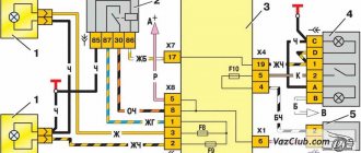
Electrical diagram of VAZ-2114 cars (without engine control system):
1 — block headlights; 2 — fog lights; 3 — air temperature sensor; 4 — electric motor of the engine cooling system fan; 5 — blocks connected to the wiring harness of the ignition system; 6 — engine compartment lamp switch; 7 — block for connecting to a single-wire type audio signal; 8 — sound signal; 9 — washer fluid level sensor; 10 — front brake pad wear sensor; 11 — oil level sensor; 12 - generator; 13 — engine compartment lamp; 14 — coolant temperature indicator sensor; 15 — starter; 16 - battery; 17 — relay for turning on fog lights; 18 — coolant level sensor; 19 — brake fluid level sensor; 20 — reverse light switch; 21 — windshield wiper gearmotor; 22 — oil pressure warning lamp sensor; 23 — block for connecting to the rear window washer electric motor; 24 — electric motor for windshield washer; 25 — instrument cluster; 26 — mounting block 2114; 27 — brake light switch; 28 — ignition relay; 29 — ignition switch; 30 — glove box lighting lamp; 31 — glove box lighting switch; 32 — rear window heating element switch; 33 — rear fog light switch; 34 — fog lamp switch; 35 — switch for external lighting lamps; 36 — alarm switch; 37 — steering column switches; 38 — switch for instrument lighting lamps; 39 — lamp for illuminating the headlight hydrocorrector scale; 40 — plug socket for a portable lamp; 41 — side direction indicators; 42 — lamp switch on the front door pillars; 43 — lamp for individual interior lighting; 44 — heater fan electric motor; 45 — additional resistor of the heater electric motor; 46 — heater fan switch; 47 — heater switch illumination lamp; 48 — lamp for illuminating the heater levers; 49 — on-board control system unit; 50 — trip computer; 51 — lamp switch on the rear door pillars; 52 — block for connecting the wiring harness of the engine control system; 53 — electric fuel pump and gasoline quantity sensor; 54 — front ashtray illumination lamp; 55 — cigarette lighter 2114; 56 — trunk lighting lamp; 57 — trunk light switch; 58 — interior lamp; 59 — parking brake warning lamp switch; 60 — rear external lights; 61 — rear internal lights; 62 — block for connection to the rear window heating element; 63 — license plate lights; 64 - additional brake signal located in the spoiler.
Conventional numbering of plugs in blocks:
- A — headlight blocks;
- B — electric fuel pump block;
- C — blocks of the mounting block, ignition switch, windshield wiper gearmotor;
- D — blocks for the interior lamp.
Wiring diagram VAZ-2114 new models
The updated engine has a new injection scheme, so it was necessary to use some new devices, as well as replace the ignition coil with a more efficient one and adapted to Euro 3 conditions. In order to comply with them, the engine had to minimize the amount of CO at start-up. And for this it was necessary to lean the mixture. Since a lean mixture ignites worse, it needed a more powerful spark to spark. This explains the use of a coil of increased power.
- block headlights;
- gearmotors for headlight cleaners*;
- fog lights*;
- ambient temperature sensor;
- sound signals;
- engine compartment light switch;
- engine cooling fan electric motor;
- generator VAZ-2114;
- low oil level indicator sensor;
- washer fluid level sensor;
- front brake pad wear sensor;
- wire ends connected to the common windshield washer pump**;
- windshield washer pump;
- headlight washer pump*;
- wire ends for connecting to the rear window washer pump on VAZ-2113 and VAZ-2114 cars;
- low oil pressure indicator sensor;
- engine compartment lamp;
- wire lug for connecting to the engine management system wiring harness;
- windshield wiper gear motor;
- starter VAZ-2114;
- block connected to the wiring harness of the ignition system on carburetor cars;
- coolant temperature indicator sensor;
- reverse light switch;
- low brake fluid level indicator sensor;
- accumulator battery;
- low coolant level indicator sensor;
- relay for turning on fog lights;
- mounting block;
- brake light switch;
- plug socket for a portable lamp;
- hydrocorrector scale illumination lamp;
- parking brake indicator lamp switch;
- block for connecting a backlight lamp;
- switch for instrument lighting lamps;
- Understeering's shifter;
- hazard switch;
- front seat heating element relay;
- ignition switch;
- rear fog lamp circuit fuse;
- front seat heating elements circuit fuse;
- door lock circuit fuse;
- front ashtray illumination lamp;
- ignition relay;
- cigarette lighter VAZ-2114;
- glove box lighting lamp;
- glove compartment light switch;
- heater fan motor;
- additional heater motor resistor;
- heater fan switch;
- heater switch illumination lamp;
- heater lever illumination lamp;
- gear motors for electric windows of the front doors;
- right front door ESP switch (located in the right door);
- gear motors for locking front door locks;
- wires for connecting to the right front speaker;
- gear motors for locking rear doors;
- wires for connecting to the right rear speaker;
- door lock control unit;
- wires for connecting to radio equipment;
- headlight wiper switch*;
- rear window heating element switch;
- rear fog light relay;
- block for connection to the heating element of the right front seat;
- rear fog light switch;
- right front seat heating element switch;
- fog light switch*;
- switch for external lighting lamps;
- left front seat heating element switch;
- block for connection to the heating element of the left front seat;
- wires for connecting to the left front speaker;
- left front door power window switch (located in the left door);
- right front door power window switch (located in the left door);
- wires for connecting to the left rear speaker;
- side direction indicators;
- dome light switches on the front door pillars;
- dome light switches on the rear door pillars;
- lampshade VAZ 2114;
- individual interior lighting lamp;
- block for connecting to the wiring harness of the electric fuel pump;
- trunk light switch;
- instrument cluster;
- trunk light;
- on-board control system display unit;
- trip computer*;
- block for connecting the wiring harness of the engine management system;
- rear exterior lights;
- rear interior lights;
- pads for connecting to the rear window heating element;
- license plate lights;
- additional brake signal located on the spoiler.
Relays and fuses VAZ 2114
F1 for 10 Amps (A) rear fog lights and rear fog light warning lamp. F2 for 10 A turn signal lamps, turn signal relay, hazard lights, hazard warning lights. F3 7.5 A lamps for interior lighting (both) and trunk, ignition lighting, powertrain control system control lamp, brake lamps, computer, if available. F4 20 A carrier, relay and rear window heating element. F5 20 A horn and its relay, cooling fan. F6 30 A power windows and their relays F7 30 A motor heater, headlight cleaner, windshield washer, cigarette lighter, glove compartment light bulb, rear window heating relay winding. F8 7.5 A right fog lamp. F9 7.5 A left fog lamp. F10 at 7.5 A left side marker, lamp signaling the inclusion of the side light, lamps for illuminating the sign, engine compartment, illumination of switches and instruments, instrument lighting switch. F11 at 7.5 A right side. F12 at 7.5 A right low beam. F13 at 7.5 A left low beam. F14 for 7.5 A left high beam and a light indicating that the high beam headlights are on. F15 at 7.5 A right far. F16 30 A - a light indicating insufficient oil pressure, brake fluid level, engagement of the parking brake, low battery, instrument cluster, relay for monitoring the health of lamps, indication of control systems, reversing lamps, turn indicators and their relays, as well as an alarm if turning mode is turned on, computer, generator excitation winding is turned on at the moment the engine starts.
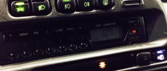
ICC pinout. Automatic light
I searched for a long time on the Internet and electrical diagrams for the pinout of the MUS block, but I never found it...
I'm tired of constantly turning my headlights on and off while wandering around the city.
If you constantly forget to turn your headlights on or off, and the PTF or DRLs are not installed, then there is a simple way out to solve this problem.
Next, I drew the main pinout of the MUS block under the light.
Option 1
To automatically light up only the low beam without the sidelights, place a jumper on pins 10 and 12. This option is good in the summer.
Option 2
To automatically light up the side lamps in the rear and front lights, place a jumper on pins 9 and 10.
This option is good in winter. During the operation of this option, an interesting feature was revealed: if you turn the ICU to the parking position or low beam, the ignition key can be pulled out and the car will continue to run. By the way, I found it convenient, I start the car, take out the key, lock the car with the alarm and go home to warm up.
Personally, in winter I use option 2. And in summer, since side lights in the taillights are not needed, I use option 1.
Both of these options are good even when the ICC is broken and you really need light to drive. The MUS block can be completely pulled out and a jumper installed, but other functions of the MUS, such as adjusting the brightness of the instrument panel and the angle of the headlights, will not be available when the block is removed.
When one of the jumper options is installed and the block is connected to the MUS, all other functions of the MUS remain operational.
If you need the jumper to be disabled, you can display a separate button. I don’t recommend making jumpers directly to contacts 9+10+12! I don’t know what will happen with this option!
Connection diagram for PTF or DRL on the MUS block using a relay. A button to turn on the PTF or DRLs after turning on the headlights, because when the headlights are turned on, the PTFs or DRLs are turned off as expected.
By the way, does anyone know how to make the American version, when when you turn on the low-range PTF, the PTF goes out and then when you turn on the turn signals, the PTF turns on only from the direction from which the turn signal was turned on?
Connection of DRL according to GOST. When the headlights are turned on, the low or high beam DRLs go out.
DRL connection diagram according to GOST on a 5-pin relay. copied from the instructions in the box
People who know about the pinout of the remaining ICC contacts, write.
Location of relays and fuses (new)
K1 - relay for turning on headlight cleaners; K2 - relay-interrupter for direction indicators and hazard warning lights; K3 - windshield wiper relay; K4 - lamp health monitoring relay; K5 - power window relay; K6 - relay for turning on sound signals; K7 — relay for turning on the heated rear window; K8 - headlight high beam relay; K9 - relay for low beam headlights; F1-F20 - fuses.
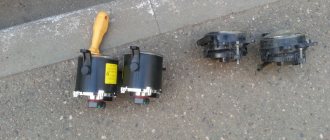
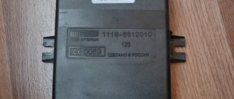
Relay for turning on rear fog lights, installed on cars of the VAZ-2108, VAZ-2109 and VAZ-2110 families.
Other markings - 22.3777
,
2302.3777
.
Lighting devices
7.18.
Ignition circuit for headlights and fog lights: 1 - headlight blocking; 2 — mounting block; 3 — headlight switch; 4 — ignition switch; 5 — external lighting switch (fragment); 6 — fog lights in the rear interior lights; 7 — fog light switch with warning lamp; 8 — indicator lamp for high beam headlights in the instrument cluster; K8 - high beam relay; K9 - relay for low beam headlights; A - the order of conditional numbering of plugs in the headlight block; B - to power supplies To turn on the headlights, relays of type 90-3747-11 or 904.3747-10 are used, installed in the mounting block. The same relays are used to turn on the horn, heated rear window and the engine cooling fan motor.
The relay switching voltage at a temperature of (23 ± 5) ° C is no more than 8V, and the winding resistance is (85 ± 8.5) Ohm.
The headlight switching diagram is shown in Figure 7.18. The main and low beam headlights are switched on via auxiliary relays K8 and K9. The control voltage is supplied to the relay coil by the headlight switch 3 if the right button of the exterior lighting switch 5 is pressed.
Regardless of the position of the switches 5, the high beam headlights can be switched on briefly by pulling the headlight switch lever 3. In this case, the voltage at pin 30 of switch 3 is supplied from pin 30 of ignition switch 4.
7.19. Ignition circuit for fog lights: 1 - fog light; 2 — relay for turning on fog lights; 3 — mounting block; 4 - fog light switch with warning lamp (left) and backlight lamp (right); 5 — external lighting switch (fragment); A - to power supplies; B - to the instrument lighting regulator
Fog lights can be installed on the front bumpers as an option on vehicles. The diagram for switching on fog lights is shown in Figure 7.19. The headlights are turned on by switch 4 through auxiliary relay 2 type 113.3747-10, installed in the engine compartment on the left wing. The fog lights can only be switched on if the external lighting is switched on with switch 5.
7.21. Diagram of direction indicators and hazard warning lights: 1 - direction indicators in the headlights; 2 — mounting block; 3 — ignition switch; 4 — alarm switch; 5 — side turn signals; 6 — direction indicators in side rear lights; 7 — instrument cluster with turn signal lamps; 8 — direction indicator switch; K2 - relay switch for direction indicators and hazard warning lights; A - to power supplies
The diagram for switching on direction indicators and warning signals is shown in Figure 7.21. The direction indicators on the right or left side are turned on by switch 8. In emergency mode, all direction indicators are turned on by switch 4. Flashing of the lights is ensured by relay switch K2 in the mounting block.
The domestic car VAZ 2114 (Samara-2) is built on the VAZ 21093 platform and is its improved version. The interior features a new instrument panel, new steering wheel, tilt steering column, power windows and a new heater. All diagrams are taken from open sources and are intended to help with self-repair of the electrical equipment of this car. Enlarge images in one click. The VAZ 2114 fuse box is located in the car interior under the instrument panel. When checking the electrical circuit of a VAZ-2114 car, it is impossible to check the functionality of the circuits for a “spark” - this can lead to depletion of the current-carrying paths of the mounting block.
Content
Principle of operation
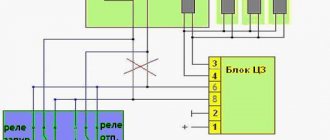
The relay is designed to turn on and off the rear fog lights of the vehicle in accordance with the algorithm according to UNECE Regulation 048:
- The rear fog lights are turned on by pressing the locking button once without locking, connected between contacts 3 (“Common”) and 5 (“On/Off”) when there is supply voltage on contacts 2 (“Fog lights”) and/or 6 (“ Low beam/high beam") of connector X1 (i.e. if the low or high beam headlights and/or fog lights are on).
- The rear fog lights are turned off by pressing the same button once or when the supply voltage is removed from contacts 2 and 6, and if the voltage is reapplied to contacts 2 and/or 6, the rear fog lights do not turn on.
When do the hazard warning lights turn on?
Its use is mandatory in the following situations:
- if a traffic accident occurs;
- if you had to make a forced stop in a prohibited place, for example due to a technical malfunction of your car;
- when in the dark you are blinded by a vehicle moving towards you;
- the hazard warning lights are also turned on in the event of towing by a motor vehicle;
- when boarding and disembarking a group of children from a specialized vehicle, an information sign must be attached to it - “Transportation of children.”
What are fog lamps for?
The main task of the PTF is to illuminate the space in front of the car. Correctly adjusted “fog lights” can illuminate a section of road 10–15 meters long. This distance is quite enough for safe movement by car in poor visibility conditions. The switching on and off of such lighting devices must be fully controlled by the driver.
Adjustment of fog lights is carried out during their installation. The procedure does not take much time, but requires care and precision. You can install the rear and front PTFs yourself.
Checking the functionality of the PTF
After the work has been carried out to connect the fog lights on the VAZ 2114, it is worth checking their functionality. If everything is done correctly, then when you turn on the side lights and press the button, voltage will begin to flow to the relay, after which the lamps should light up. If you turn off the headlights, the fog lights should also go off, regardless of the position of the button. If everything is done correctly, then the next step is to adjust the light beam so as not to blind oncoming drivers. Having done this by eye, the light from the fog lights should be 10-15 meters ahead of the car, but no more. It is best to contact a service station with special equipment to adjust the headlights, or read more detailed instructions on how to do it yourself. Useful: How to adjust headlights and PTF on a VAZ 2114? Correct adjustment is the key to safety on the road, not only for you, but also for other road users. By installing fog lights, car enthusiasts want to get not only direct functionality, but also improve the appearance of the car. Since public roads require driving with the optics always on, fog lights can take over this function. Thus, you can install high-quality lamps in them and spend less on constantly replacing burnt-out light elements in the headlights. As described earlier, at the most unexpected moment, PTF can help you out when visibility deteriorates when driving along the highway during fog.
Next, I created an ingeniously simple automatic switching on of the low beam without dimensions and without turning on the MUS. I connected the button to pins 10 and 12 on the MUS block. I stuck the button into the free socket from the cigarette lighter, removing the heater air duct lining and the diagnostics cover under the ashtray. Carefully pushed the wire there. Next, I ran the wire under the rug (or rather, under the rug under the carpet under the driver’s feet) to the fuse mounting block and soldered it to pins 10 and 12 on the MUS block. I installed a button for the fog lights so that this function can be turned off when it is not needed. Before this, contacts 10 and 12 on the MUS block were simply shorted. What yes, look at the diagram in photo 4
How can you install PTF on a VAZ 2113, 2114, 2115
Installation of fog lights on a car can be done in different ways. The car owner chooses a specific option based on his own capabilities, preferences and wishes. There are three main ways to install PTF:
- Purchasing a bumper with pre-installed fog lights. Similar parts are presented in a wide variety at tuning studios, where they can be purchased and installed immediately. Adjustment and connection are carried out by service specialists. The disadvantage of this method is that the cost of the work is too high.
One way to install foglights is to buy a bumper with already built-in PTFs
Front bumper VAZ 2115 with holes for fog lights
Purchase and subsequent installation of a set of “fog lights” from the PTF kit
Headlight installation
How to connect fog lights? The installation and connection procedure is described in detail below. Let’s make a reservation right away - if necessary, you can install xenon lamps in the fogs. Xenon in PTF will burn much brighter when compared with traditional incandescent lamps, but its cost will be an order of magnitude higher. Since the bumper on the VAZ 2114 does not have appropriate places for installing fog optics, the car owner will have to make them on his own.
All work on installing optics is carried out on the dismantled bumper. If you don’t know how to remove this body element, then you just need to unscrew the fasteners that secure it. The bumper itself needs to be cleaned; it is advisable to install it at the level of the lower air intake, under the headlight optics. Installation of lights must be done in specially designated places on the bumper - the so-called glasses.
These glasses must be marked in accordance with the dimensions of the optics themselves, after which the corresponding holes must be made in the bumper. The holes are cut using a jigsaw, and it is advisable to sand the sharp edges on them with sandpaper or a file. The PTF should fit into the hole as tightly as possible, so they must be securely secured with clamps. When the installation of the optics is completed, the bumper can be put back on the car.
Installation diagram of fog lights
The connection of fog lights is carried out according to certain rules. They, first of all, relate to the placement of PTF on the car. The locations for installing headlights are strictly defined.
Layout of daytime running lights
Manufacturers of modern car models pre-mark the PTF installation locations on the bumpers. As a rule, such lighting elements are most often available in the luxury version of the car. If the headlights themselves are missing, then their installation sites are closed with special plugs.
Distance at which fog lights can be placed
Second installation option
It will be much easier for car owners whose bumper already has space for mounting fog lights. Then you don't need to buy any fuses. All that is required is a pair of new fog lights and up to 100 centimeters of wire (in reserve).
This algorithm for installing PTFs is suitable not only for foreign cars, but also for all domestic cars on which the manufacturer has provided a mounting location for the optics. For example, on VAZ 2110 and 2114 cars, connecting foglights in this way takes no more than 20-40 minutes (and this despite the fact that the car owner has no experience installing such equipment on a vehicle).
How to install a PTF: necessary materials and tools
Installation of fog lights, regardless of the chosen installation method, requires the presence of certain parts and tools, without which it is impossible.
What are the button and relay for?
A special button and relay are a must - “fog lights” are very powerful equipment for car electrical wiring. The absence of such parts can provoke high current loads on the terminals and the ignition switch, which will cause burnout of contacts, damage and overheating of the insulation protection and short circuit with failure of the electrical network.
In order to install fog lights on a VAZ, you need to assemble certain parts in advance or purchase a ready-made kit. The cost of such a set rarely exceeds one thousand rubles.
The PTF kit includes:
- wires with blocks and terminals for a specific VAZ model. There are three of them as standard: one connects the headlights, the second goes to the relay from the switch, and the third goes from the relay to the fuse box;
Set of wires with terminals and blocks for installing PTF
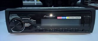
Fog lamp relay for VAZ 2113, 2114, 2115
Button to turn on PTF on Lada
Plastic ties and clips that secure wires
PTF for VAZ 2115
Which PTFs should you prefer? The headlights themselves are chosen by the driver to his taste, but the main thing when choosing is not to make a mistake with the power, so as not to overload the generator and the car’s electrical wiring. It is better not to purchase headlights with xenon: the generator has a certain power reserve, but is not designed for too high loads. Regular light bulbs will be sufficient.
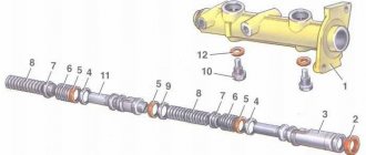
PTF connection diagram
Voltage is supplied to the electrical circuit by contact B+ from the generator. The mass is taken from the car body, not far from the location where the PTFs are installed. They begin to work when the switch key is pressed, provided that the low or high beam is working. To reduce the load on the contacts, a relay is connected to the circuit, which is installed from the factory in the engine compartment on the left mudguard; in addition, three fuses F8, F9, F10 are installed in the mounting block, which protect the fog light circuit.
How to connect fog lights with your own hands
Before directly installing the headlights, their location is determined. In the case of the VAZ 2115 car, the bumper already has standard holes for installing additional lighting fixtures. Similar ones can be cut in the bumpers of VAZ 2113 and VAZ 2114.
There is no need to spoil the appearance of the bumper - fog lights are easily installed on special brackets. Many PTF kits contain special decorative plugs that add attractiveness and neatness to the installed headlights and facilitate the installation process.
Installation and connection algorithm
- Installation of a power button in the car interior. In the case of the VAZ-2114, the place for the button is on the left side of the driver on the front panel. However, its placement can be arbitrary - the main thing is that it is convenient for the driver to drive the car. Often, PTF power buttons are installed instead of plugs on the control panel.
A PTF activation button is installed in the cabin in a place convenient for the driver.
The power button is connected, chips are connected to it
Under the hood there is a block to which the PTF relay will be connected
The wiring harness connects to the fuse box
The PTF relay is located in the engine compartment
PTF connection diagram
Wiring diagram for connectors and terminals of fog lights
The functionality of the entire connection can be checked by turning on the side lights - only then will the fog lights work.
Fog lights only function when the side lights are on
After completing the installation of the PTFs on the car, they only need to be adjusted correctly. The flow of light should not blind drivers in the oncoming lane.
What requirements must PTFs meet?
Finally, we note what rules modern fog lights must meet:
- In order to illuminate the road surface well, this type of optics must have a clear beam boundary at the top. Thus, the light in the headlights is scattered slightly above the horizontal plane.
- If the car manufacturer has not provided space for PTF fasteners, do not install them above the headlights under any circumstances. Try to place them as close to the roadway as possible. The lower this optics is, the better it will “break” the foggy barrier in front of you. But don’t forget about the car’s ground clearance. If the headlight is located at a distance of 10 centimeters from the asphalt, then during rainy weather it will constantly get wet, and water that gets inside the reflector will linger there for several weeks. And throughout this period the glass will be cloudy, and the quality of lighting will deteriorate significantly. On cars like the VAZ “classic”, the optimal solution to the problem is to install the PTF under the steel bumper. This way you will “kill two birds with one stone.” Firstly, at such a distance from the road the headlight will never get wet, and secondly, it looks very attractive and does not disfigure the appearance of the car. But where there is no point in installing PTF at all is on the roof (owners of SUVs often do this). The benefit from such illumination is zero, but such a technique will be fully blinding.
- If this is not factory optics, it is advisable to purchase it with special plugs. This way you will significantly increase the service life of your headlights and ensure their high safety when driving on rough terrain. And the cap protects the fog lights all year round at any time of the day.
- During operation, it is important to prevent clouding or fogging of the optics glass. To prevent this, you should regularly treat their surface with special polishes (at least once every 2-3 months).