The VAZ 2114 (Samara-2) car is built on the VAZ 21093 platform and is an improved version of it. The first prototype of the hatchback was assembled back in 2000. A year later, the Volzhsky Automobile Plant produced the first pilot batch of 50 VAZ-2114 cars, and in the same 2001 the hatchback was first introduced to the market. The interior features a new instrument panel, a new steering wheel, an adjustable steering column, power windows and a new heater. Years of production 2114: 2001—2013
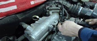
The fourteenth model was previously equipped with a 1.5 liter eight-valve engine, borrowed from the VAZ 2111 model with an injector. A little later it was replaced by the VAZ 11183-1000 version, which complies with the Euro-3 standard. The VAZ 2114 injector received a more powerful engine, and this is one of the reasons that the wiring of the 2114 has also changed.
A wiring harness has been added for connecting to the electronic switch. A harness has also appeared for connecting to the ignition module terminal.
Replacing high-voltage wires will require additional attention, because the connection procedure depends on the year of manufacture of the car. Until 2004, 4-pin ignition modules were installed, and after that - 3-pin. Connecting the adsorber valve to the injection system controller also provided another additional element. An adsorber is an electromechanical device used for ventilation and removal of condensate in a gas tank. Complications also affected the interior part. The dashboard received improvements in the form of the appearance of a BC (on-board computer), a new instrument panel and a change in the position of the glove compartment.
Car modifications 2114
VAZ-21140 . Modification with an 8-valve injection engine VAZ-2111, 1.5 liters and 77 horsepower. Serial production from 2003 to 2007
VAZ-21144 . Modification with an 8-valve VAZ-21114 engine, 1.6 liters and 81.6 horsepower. Years of serial production: 2007-2013.
VAZ-211440 . Another modification released in 2007, it was equipped with a VAZ-11183 engine with a volume of 1.6 liters and a power of 82 horsepower. The car was discontinued in 2013.
VAZ-211440-24 . Released in 2009, a modification with an injection 16-valve VAZ-21124 engine with a volume of 1.6 liters and a power of 89.1 horsepower. Discontinued in 2013.
VAZ-211440-26 . Modification with a 16-valve injection engine VAZ-21126, which complies with the Euro-3 environmental standard, with a volume of 1.6 liters and a power of 98 hp. The car was produced from 2010 to 2013.
Wiring diagram VAZ-2114 for old models
Electrical diagram of car 2114: 1 – headlight; 2 [Installed on a part of the car] – fog lamp; 3 – ambient temperature sensor; 4 – electric engine radiator fan; 5 – block for connection to the wiring harness of the engine control system; 6 – engine compartment lamp switch; 7 [Installed on a part of the car] – reserve block for connecting an audio signal with one terminal (the negative terminal is connected to the body); 8 – sound signal; 9 – liquid level sensor in the windshield washer reservoir; 10 [Installed on a part of the car] – brake pad wear sensor; 11 – low oil level sensor; 12 – generator; 13 [Installed on a part of the car] – engine compartment lamp; 14 – temperature indicator sensor; 15 – starter; 16 – battery; 17 [Installed on a part of the car] – relay for turning on fog lights; 18 – coolant level sensor in the expansion tank; 19 – sensor of insufficient brake fluid level; 20 – reverse light switch; 21 – windshield wiper gear motor; 22 – emergency oil pressure sensor; 23 – rear window washer electric pump; 24 – electric pump for windshield washer; 25 – instrument panel; 26 – mounting block of fuses and relays; 27 – brake signal switch; 28 – ignition relay; 29 - ignition switch (lock); 30 – glove box lighting lamp; 31 – switch for the glove compartment lighting lamp; 32 – rear window heating switch; 33 – rear fog light switch; 34 [Installed on a part of the car] – fog light switch; 35 – combined switch for side lights and headlights; 36 – alarm switch; 37 – steering column switches; 38 – brightness control for instrument lighting; 39 – illumination lamp for the headlight hydraulic adjustment control handle; 40 – socket for connecting a portable lamp; 41 – side direction indicator; 42 – interior lighting switch (front door open sensor); 43 – interior lamp; 44 – electric fan of the ventilation and heating system; 45 – additional resistor of the electric fan of the ventilation and heating system; 46 – switch for operating modes of the electric fan of the ventilation and heating system; 47 – illumination lamp for the handle of the operating mode switch of the electric fan of the ventilation and heating system; 48 – backlight lamp for the heater control unit; 49 – display unit of the on-board control system; 50 [Installed on part of the car] – trip computer; 51 – interior lighting switch (rear door open sensor); 52 [Installed on a part of the car] – block for connecting a clock; 53 – fuel module; 54 – ashtray illumination lamp; 55 – cigarette lighter; 56 – interior lamp; 57 – switch for the parking brake warning lamp; 58 – rear light; 59 – license plate light; 60 – additional brake light; 61 – heating element for heating the rear window; 62 – rear window wiper gear motor; A – pin numbers in the connecting blocks.
Electronic control unit
The wiring diagram of the VAZ-2114 ECU turns out to be very complex, since a large number of sensors and actuators are connected to it.
The electronic control unit is the “brain” of the entire system; it consists of the following components:
- Housing made of plastic and metal.
- At the heart of the circuit is a microcontroller.
- Sensors are connected to the microcontroller inputs through matching devices.
- Signal amplifiers, electronic keys and relays are connected to the controller outputs.
The microcontroller allows you to send signals to the actuators, depending on how the engine is operating. The ECU memory contains the algorithm for the operation of all systems. Moreover, the wiring diagram of the VAZ-2114 (injector) 8 valves differs from the V16, since a little more parameters are needed to control the engine.
VAZ-2114 diagram (second option)
Electrical diagram of VAZ-2114 cars (without engine control system):
1 – headlights; 2 – fog lights; 3 – air temperature sensor; 4 – electric motor of the engine cooling system fan; 5 – blocks connected to the wiring harness of the ignition system; 6 – engine compartment lamp switch; 7 – block for connection to a single-wire type audio signal; 8 – sound signal; 9 – washer fluid level sensor; 10 – front brake pad wear sensor; 11 – oil level sensor; 12 – generator; 13 – engine compartment lamp; 14 – coolant temperature indicator sensor; 15 – starter; 16 – battery; 17 – relay for turning on fog lights; 18 – coolant level sensor; 19 – brake fluid level sensor; 20 – reverse light switch; 21 – windshield wiper gearmotor; 22 – oil pressure warning lamp sensor; 23 – block for connecting to the rear window washer electric motor; 24 – electric motor for windshield washer; 25 – instrument cluster; 26 – mounting block 2114; 27 – brake light switch; 28 – ignition relay; 29 – ignition switch; 30 – glove box lighting lamp; 31 – glove box lighting switch; 32 – rear window heating element switch; 33 – rear fog light switch; 34 – fog lamp switch; 35 – switch for external lighting lamps; 36 – alarm switch; 37 – steering column switches; 38 – switch for instrument lighting lamps; 39 – illumination lamp for the headlight hydrocorrector scale; 40 – plug socket for a portable lamp; 41 – side direction indicators; 42 – lamp switch on the front door pillars; 43 – canopy for individual interior lighting; 44 – heater fan electric motor; 45 – additional resistor of the heater electric motor; 46 – heater fan switch; 47 – heater switch illumination lamp; 48 – backlight lamp for heater levers; 49 – on-board control system unit; 50 – trip computer; 51 – lamp switch on the rear door pillars; 52 – block for connecting the wiring harness of the engine control system; 53 – electric fuel pump and gasoline quantity sensor; 54 – front ashtray illumination lamp; 55 – cigarette lighter 2114; 56 – trunk lighting lamp; 57 – trunk light switch; 58 – interior lamp; 59 – parking brake warning lamp switch; 60 – rear external lights; 61 – rear internal lights; 62 – block for connection to the rear window heating element; 63 – license plate lights; 64 – additional brake signal located in the spoiler.
Conventional numbering of plugs in blocks:
- A – headlight blocks;
- B – electric fuel pump block;
- C – blocks of the mounting block, ignition switch, windshield wiper gearmotor;
- D – blocks for the interior lighting.
Useful: VAZ tachometer connection diagram
Wiring diagram VAZ-2114 new models
The updated engine has a new injection scheme, so it was necessary to use some new devices, as well as replace the ignition coil with a more efficient one and adapted to Euro 3 conditions. In order to comply with them, the engine had to minimize the amount of CO at start-up. And for this it was necessary to lean the mixture. Since a lean mixture ignites worse, it needed a more powerful spark to spark. This explains the use of a coil of increased power.
- block headlights;
- gearmotors for headlight cleaners*;
- fog lights*;
- ambient temperature sensor;
- sound signals;
- engine compartment light switch;
- engine cooling fan electric motor;
- generator VAZ-2114;
- low oil level indicator sensor;
- washer fluid level sensor;
- front brake pad wear sensor;
- wire ends connected to the common windshield washer pump**;
- windshield washer pump;
- headlight washer pump*;
- wire ends for connecting to the rear window washer pump on VAZ-2113 and VAZ-2114 cars;
- low oil pressure indicator sensor;
- engine compartment lamp;
- wire lug for connecting to the engine management system wiring harness;
- windshield wiper gear motor;
- starter VAZ-2114;
- block connected to the wiring harness of the ignition system on carburetor cars;
- coolant temperature indicator sensor;
- reverse light switch;
- low brake fluid level indicator sensor;
- accumulator battery;
- low coolant level indicator sensor;
- relay for turning on fog lights;
- mounting block;
- brake light switch;
- plug socket for a portable lamp;
- hydrocorrector scale illumination lamp;
- parking brake indicator lamp switch;
- block for connecting a backlight lamp;
- switch for instrument lighting lamps;
- Understeering's shifter;
- hazard switch;
- front seat heating element relay;
- ignition switch;
- rear fog lamp circuit fuse;
- front seat heating elements circuit fuse;
- door lock circuit fuse;
- front ashtray illumination lamp;
- ignition relay;
- cigarette lighter VAZ-2114;
- glove box lighting lamp;
- glove compartment light switch;
- heater fan motor;
- additional heater motor resistor;
- heater fan switch;
- heater switch illumination lamp;
- heater lever illumination lamp;
- gear motors for electric windows of the front doors;
- right front door ESP switch (located in the right door);
- gear motors for locking front door locks;
- wires for connecting to the right front speaker;
- gear motors for locking rear doors;
- wires for connecting to the right rear speaker;
- door lock control unit;
- wires for connecting to radio equipment;
- headlight wiper switch*;
- rear window heating element switch;
- rear fog light relay;
- block for connection to the heating element of the right front seat;
- rear fog light switch;
- right front seat heating element switch;
- fog light switch*;
- switch for external lighting lamps;
- left front seat heating element switch;
- block for connection to the heating element of the left front seat;
- wires for connecting to the left front speaker;
- left front door power window switch (located in the left door);
- right front door power window switch (located in the left door);
- wires for connecting to the left rear speaker;
- side direction indicators;
- dome light switches on the front door pillars;
- dome light switches on the rear door pillars;
- lampshade VAZ 2114;
- individual interior lighting lamp;
- block for connecting to the wiring harness of the electric fuel pump;
- trunk light switch;
- instrument cluster;
- trunk light;
- on-board control system display unit;
- trip computer*;
- block for connecting the wiring harness of the engine management system;
- rear exterior lights;
- rear interior lights;
- pads for connecting to the rear window heating element;
- license plate lights;
- additional brake signal located on the spoiler.
Numbering order of plugs in blocks:
A – headlight units and headlight cleaners; B – cigarette lighter; B – mounting block, instrument cluster, ignition switch, windshield wiper and other electrical components (for blocks with a different number of plugs, the numbering order is similar); G – relay for turning on the rear fog light; D – alarm switch; E – electric window motors and door lock motors; F – interior lamp.
In the instrument panel wiring harness, the second ends of the white wires are brought together into one point, which is connected to the instrument lighting switch (except for the white wire, from plug “4” of block “X2” of mounting block 28 to display block 83 of the on-board control system). The second ends of the black wires are also brought together to points connected to ground. The second ends of the yellow wires with a blue stripe are brought together to a point connected to plug “4” of the “X1” block of the mounting block. The second ends of the white wires with a red stripe are brought together to a point connected to plug “10” of the “X4” block of the mounting block. The second ends of the orange wires are brought together to a point connected to plug “3” of the “X4” block of the mounting block.
Explanations for the 8-pin injector block: white-red and blue - for the check light bulb, blue-red - ignition, gray - speed sensor, brown-red - tachometer, blue-white - driver's door switch (for the immobilizer), green- red - K-line (may not exist), green - fuel consumption. Next to it is a pink wire - to the fuel level sensor.
See the complete diagram in one file below (click to enlarge):
Relays and fuses VAZ 2114
F1 for 10 Amps (A) rear fog lights and rear fog light warning lamp. F2 for 10 A turn signal lamps, turn signal relay, hazard lights, hazard warning lights. F3 7.5 A lamps for interior lighting (both) and trunk, ignition lighting, powertrain control system control lamp, brake lamps, computer, if available. F4 20 A carrier, relay and rear window heating element. F5 20 A horn and its relay, cooling fan. F6 30 A power windows and their relays F7 30 A motor heater, headlight cleaner, windshield washer, cigarette lighter, glove compartment light bulb, rear window heating relay winding. F8 7.5 A right fog lamp. F9 7.5 A left fog lamp. F10 at 7.5 A left side marker, lamp signaling the inclusion of the side light, lamps for illuminating the sign, engine compartment, illumination of switches and instruments, instrument lighting switch. F11 at 7.5 A right side. F12 at 7.5 A right low beam. F13 at 7.5 A left low beam. F14 for 7.5 A left high beam and a light indicating that the high beam headlights are on. F15 at 7.5 A right far. F16 30 A - a light indicating insufficient oil pressure, brake fluid level, engagement of the parking brake, low battery, instrument cluster, relay for monitoring the health of lamps, indication of control systems, reversing lamps, turn indicators and their relays, as well as an alarm if turning mode is turned on, computer, generator excitation winding is turned on at the moment the engine starts.
Voltage regulator operation
But there is one huge problem - depending on the crankshaft speed, the generator can produce voltage from 10 to 30 Volts, and such a variation is unacceptable. Therefore, it is necessary to stabilize the voltage at the same level - 12 V. In fact, of course, the generators produce a little more - 13.6-14.6 V. Only in this case will the battery be charged normally. You can stabilize the output voltage, but the problem is that the current consumption is very high.
And the zener diode must have considerable dimensions and, accordingly, cost. But it is much easier to stabilize the power supply to the rotor winding. If the voltage applied to it is stable, then the magnetic field will not change under any circumstances. This action is carried out using a voltage regulator. The maximum current consumption of the excitation winding is no more than 2 A. Structurally, the regulator is combined with a brush assembly.
VAZ-2114 wiring harness diagrams
Instrument panel harness
Glove compartment lighting harness
Front harness (without fog lights)
Rear harness VAZ-2114
Wiper Harness
Additional harness
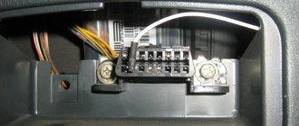
Connects to the instrument panel, the connector is next to the hood handle. Pink - door lock, permanent plus, fuse hangs next to the hood release handle. White and black - on the door for electric windows, plus during ignition, switched on through a relay and fuse in the mounting block. Also in the photo is the wiring for the radio speakers.
Right door harness
Connects to an additional harness.
Left door harness
Connects to an additional harness.
Seat heating harness
The gray wire is connected to the connector where the additional harness is connected (to the gray wire if there is one), plus when igniting, the relay is attached next to the mounting block and the fuse is located next to the hood handle. The white wire is connected to the additional harness, button illumination.
How does a generator work?
When the engine is stopped, the rotor winding is powered. Therefore, there is a magnetic field around it. But since the rotor does not rotate, the field is stationary. Therefore, one of the mandatory operating conditions of the generator set is not met - the magnetic field must be constant and moving. All conditions are met only when the starter begins to spin the crankshaft. In this case, the generator generates voltage supplied to the battery.
But the design feature of any car generator is that it produces alternating current. Moreover, three phases appear at the output, and alternating direct current is needed to power all consumers. Otherwise, all the sub-panel wiring of the VAZ-2114, the diagram of which is presented below, will simply burn out.
To rectify alternating current, a block of semiconductor silicon diodes is used. The design of a generator with three phases at the output is used for one simple reason - there is much less ripple. A capacitor is installed at the output of the rectifier - with its help it is possible to get rid of the entire alternating component of the current.