Dear customers, in order to avoid errors when sending the VAZ 1118-00 Lux electrical package control unit, in the “Comment” line indicate your car model, year of manufacture and vehicle equipment (norm, standard or luxury).
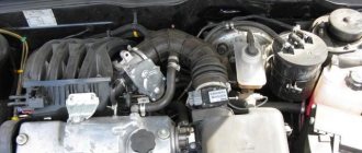
The central body electronics unit (CBEC) - 1118-3763040-00 is responsible for all the electronics on the car - except for the operation of the engine, its sensors and everything related to the fuel mixture and gearbox.
TsBKE 1118-3763040 is designed to perform the following functions:
– interior lighting, ceiling light;
– rear fog lights;
– direction indicator switch;
– car doors (front right door, front left door, rear right door, rear left door);
– heated rear window;
– trunk lighting, courtesy lamp;
TsBKE 2170-3763040 includes an IMMO, TsBKE 1118-3763040 has an IMMO as a separate unit, and the connection diagrams are accordingly different.
1118 – 3763040-00 only for Lada Kalina Lux.
Ambient temperature from minus 40 to plus 45 °C;
Relative humidity of ambient air at a temperature of 27 °C 90%;
Atmospheric pressure from 84 to 106.7 kPa (from 630 to 800 mmHg);
The operating supply voltage range is from 9 to 15 V.
Other articles of the product and its analogues in catalogues: 11180 376304000.
VAZ 1117-1119 Lux.
Any breakdown is not the end of the world, but a completely solvable problem!
How to independently replace the electrical package controller on a Lada Kalina Lux?
With the online store Discounter AvtoAzbuka, repair costs will be minimal.
Just COMPARE and BE SURE.
Don't forget to share the information you find with your friends and acquaintances, as they may also need it - just click one of the social networking buttons below.
The Kalina electrical package control unit is used to automatically raise and lower windows and control doors. Additionally, it makes it possible to control alarm activation and trunk opening.
If we are talking about the luxury configuration of Kalina 2, then the electrical package control unit is responsible for blocking the ignition switch. That is why any malfunctions in its operation negatively affect the driving performance of the vehicle.
Stories from our readers
“Fucking basin. "
Hi all! My name is Mikhail, now I’ll tell you a story about how I managed to exchange my two-wheeler for a 2010 Camry. It all started with the fact that I began to be wildly irritated by the breakdowns of the two-wheeler, it seemed like nothing serious was broken, but damn it, there were so many little things that really started to irritate me. This is where the idea arose that it was time to change the car to a foreign car. The choice fell on the melting Camry of the tenth years.
Yes, I had matured morally, but financially I just couldn’t handle it. I’ll say right away that I am against loans and taking a car, especially not a new one, on credit is unreasonable. My salary is 24k a month, so collecting 600-700 thousand is almost impossible for me. I started looking for different ways to make money on the Internet. You can’t imagine how many scams there are, what I haven’t tried: sports betting, network marketing, and even the volcano casino, where I successfully lost about 10 thousand ((The only direction in which it seemed to me that I could make money was currency trading on the stock exchange, they call it Forex. But when I started delving into it, I realized that it was very difficult for me. I continued to dig further and came across binary options. The essence is the same as in Forex, but it’s much easier to understand. I started reading forums, studying trading strategies. I tried it on a demo account, then opened a real account. To be honest, I didn’t manage to start earning money right away, until I understood all the mechanics of options, I lost about 3,000 rubles, but as it turned out, it was a precious experience. Now I earn 5-7 thousand rubles a day. I managed to get the car buy after half a year, but in my opinion this is a good result, and it’s not about the car, my life has changed, I naturally quit my job, I have more free time for myself and my family. You’ll laugh, but I work directly on the phone)) If If you want to change your life like me, then here’s what I advise you to do right now: 1. Register on the site 2. Practice on a Demo account (it’s free). 3. As soon as you get something on the Demo account, top up your REAL ACCOUNT and go to REAL MONEY! I also advise you to download the application to your phone, it’s much more convenient to work from your phone. Download here.
In the case of ESP power buttons , everything is much simpler; no additional control units are required. You just need to connect the buttons correctly.
Remember the main thing: power buttons are produced by Avar, and multiplex buttons are produced by Itelma.
Installation of Kalina power window buttons on a VAZ 2110
Installation of the Kalina window lifter unit on a VAZ 2110
It will not be possible to install 1118-3763080 - a fashionable unit with 4 ESP buttons, central locking (CL) and mirror adjustment, because they are all multiplex. And this is logical, because pulling such a mass of power wires through the door will be problematic.
And there are power units, but only with 2 ESP and central locking buttons (for example, 1118-3709810-10 (351.3769)). You can buy one for 600 rubles. Wiring diagram for the ESP Kalina block and pinout : Main connector:
- motor in driver's door
- motor in driver's door
- mass (only one can be combined inside)
- +12V for driver's window
- weight
- +12V for passenger window
- absent
- dimensions
- to the 3rd leg of the button in the passenger door
- to the 6th leg of the button in the passenger door
Central lock button:
- closing
- weight
- absent
- dimensions
- backlight weight
- absent
- opening
You can buy the Kalinovsky unit and ESP control buttons in online stores (section “Spare parts”). And if you modify the VAZ-1118 control unit with electric windows , you can install 4 buttons. You just need to combine the block 1118-3709810-10 with two one-piece buttons 2170-3763040. Thus, the ESP power unit of 4 buttons and central locking is ready! Instructions on how to move the ESP control unit from the tunnel to the driver's door.
By the way, it is not at all necessary to pull thick wires through the door if you install a glass closer (for example, beta10, which has thin low-current inputs).
Controls
What to do if the rear window heating does not work, and the diagnostics showed that all elements of the system are working? Perhaps the reason for this could be the power button. When the heating is turned on, a light indicator on the button lights up, indicating the operation of the system. So, the toggle switch is in the “on” position, the indicator light is on, but no warm-up occurs. This indicates that the working contacts of the toggle switch are burnt out or worn out over time, and therefore no energy is supplied for heating. In case of this breakdown, you need to replace the button, since it is almost impossible to repair a damaged one.
Kalina ESP unit (352.3769) and Priora SE mirrors. VAZ 2110.
Good afternoon. Today we’re talking about connecting the mirrors of the Priora SE (turn signal, electric adjustment and heating). The remote control from the viburnum fret (352.3769) was selected as the control unit. It is still under normal power wiring. Similar to single buttons, only assembled. Does not require a comfort unit, unlike options for 4 electric windows.
I'll start by selecting block 352.3769. (1118-3709810)
It turns out there are two types in stores. There is an original produced by JSC "AVAR" and its clone. The first time I grabbed a clone... Below are the details you need to pay attention to:
1. Various mirror control joysticks
2. Differences in the type of markings on the bottom of the case (paint-stamp and volumetric (plastic)).
I found the information on the website of JSC AVAR. Section dedicated to counterfeit products. After 10 days I returned the money and took the original. As a claim, I used a printout from the “AVAR” website and a completed application. Ps: I bought the fake one for 736 rubles, and the original for 725 rubles. According to reviews, the clone works fine and is assembled well, but history is silent about durability.
Pads, terminals, etc.
At this point I wanted to pay special attention to the connecting elements. I spent a long time looking for original connectors for mirrors (Tyco 175507-02), they are not available in stores. For now I left it on the computer, it works! Computer “combs” are suitable, almost all have a 1 in 1 pitch with our black Tyco block. Can be purchased at radio supply stores and electronic components stores.
To the ESP block.
Names:
Power window switch block AMP 1-929623-1, central locking 2106-3724564, exterior mirror control unit contacts 928 999-1, contact insert 1534125-1 and cover AMP 1-1534171-1 There are no problems with the central locking block, it is standard . At ESP I bought a control unit that was native to this and was found in auto parts stores.
(The small black block with brown and yellow wires did not fit.) The cable from the old computer came to the output from the mirror control panel. It is 10pin, but even with a shift to the side it fits into the socket without any problems. Any interfering plastic protrusions can be trimmed, in this case they are not needed. 1) You can shorten IDE, FDD.
2) My version is 10 pin.
If you don’t have one ready-made, you can assemble it. All components are sold in electronic components stores.
3) Original version Consists of several parts + contact group:
What and where. Connection.
Installation in the door card.
Preparing a paper template (pattern) for the base of the ESP block. I did exactly this myself, then I found all the necessary sizes, they will be presented below.
Drawings of the base and geometry of the block:
Thank you for your attention. Happy New Year to you!)
Non-specific types of services
Even if the rules for safe operation of the vehicle are observed, the heater control unit may require servicing or replacement. This happens as a result of sudden switching of the heating knob of the Lada Kalina car. The operating instructions indicate that you must wait until the system warms up to a minimum, otherwise expensive repairs will be required.
From a financial point of view, the stove control unit will not be cheap, so its careful operation will save the family budget.
The heater control unit cannot be replaced independently due to the need to use special equipment. Much less often problems arise at the level of the engine control system.
The need to visit a service station will be caused by driving on a gravel road, an accident, or the result of unprofessional maintenance. The engine management system is responsible for fuel injection, so any deviations in its operation immediately put the car on hold. How long it will take to replace the engine control unit will be decided by the technician after an inspection.
It is cheaper, but repairs take much longer when the body electronics unit comes under attack. The problem can only be diagnosed in a service center. The duration is due to the fact that if the engine control unit can be replaced as a single whole, then part of the wiring must be changed along with the electronics.
Voltage surges or a simple short circuit can damage a certain sector. The light control unit will be the first to tell you about this.
Incorrectly working turn signals or emergency lights are the first sign indicating a failure in the electronic component of the car. There is no point in delaying a visit to the service center. Otherwise, the ESP unit responsible for dynamic stabilization will come under attack. Even with minor problems, the driver will notice a decrease in the lateral dynamics of the vehicle.
Lada Kalina requires regular maintenance as prescribed by the manufacturer. If the specified deadlines are met, each element of the system will work properly.
Auto manufacturers today use many technological solutions to ensure more comfortable driving. One of such devices is CBKE. What is the central unit of body electronics Kalina 2 needed for, what functions does it perform and what malfunctions are typical for it - read in this article.
ESP block from Kalina on VAZ 2110
The Kalinovsky block looks more beautiful than the tenth block, so I decided to install it. For a very long time I could not find a working and understandable connection diagram, they were all complicated and abstruse. In general, below are the schemes that actually work. I installed the block and also made a duplicate passenger button. For me, this is a very useful modification, convenient, beautiful))
Comments 45
It turned out well, but personally, all these buttons rattle and jump when I listen to music. I don’t know what to do, can you tell me?
I myself don’t know yet whether they will rattle while I’m assembling the interior)) In general, they shouldn’t rattle, maybe yours are worn out and that’s why
DIY heating repair
I remember distant times when this was practically impossible! Now technology has come so far - you can buy a rear window repair kit just to restore these narrow strips. I suspect that there is some kind of metallized composition or paint - but it is called conductive glue.
This glue can withstand temperatures from – 60 to + 100 degrees Celsius. This is exactly what we need to buy. The only thing I want to tell you is - don’t take the cheapest composition, now in my opinion it’s about 150 - 200 rubles, take a little more expensive one, about 300 - 400 rubles, such compositions work much longer.
Connection diagram and pinout of VAZ power window button
Electric windows (ESP) are convenient devices for controlling the side windows of a car, which are controlled by a special button and make it possible to lower or raise the side windows without rotating the previously used handles. This option is provided only in some modifications of the VAZ car, but nothing prevents you from purchasing a ready-made unit and installing it yourself.
The most preferred are rack type ESPs , so as an example we will describe the process of their installation.
The connection diagram for the window regulator on a VAZ-2110 car is as follows:
- remove the negative terminal from the car battery to stop the supply of voltage to the on-board power supply network;
- we take the wires that come standard with rack-and-pinion window lifts and make a kind of harness out of them that makes connection easy;
- remove the car mounting block, which will require unscrewing the self-tapping screw that secures the special latch;
- turn the block over and carefully install block Ш1 of the pre-prepared wiring harness into the corresponding connector;
- dismantle the door trim;
- we pull the wires to the electric window drive. To do this, you will need to carefully pass them through the holes in the door itself and the body pillar on the desired side.
After this, buttons or keys are installed that will be used to control the power windows. Depending on your desire, they can be attached either to the door trim of a VAZ-2110 car, or to an existing control panel. In the first case, you will need to use an additional wire, which will allow you to equip the key backlight.
Types, design and characteristics of rear window heating switches
All rear window heating switches are divided into two types according to design and operating principle:
- Key switches;
- Push-button switches.
Key switches are toggle switches in which the movable contact plate is moved using a key of one shape or another. To close the circuit, press one part of the key, and to open it, press the opposite part. Typically, two-position switches with an “On” position are used to control the defroster. and “Off,” but there are also three-position switches with a middle position and the ability to turn on various heater modes.
Push-button switches are switching devices with a button that is locked in a pressed (recessed) position. To close the circuit, press the button - it will sink into the body and lock in this position, providing current to the heater.
Keys and switch buttons can have a standard neutral design or be made for specific car models. Most often they are black, so they can be installed on various vehicles without disturbing the overall design of the dashboard.
The basis of both types of switches is a contact group, which consists of fixed contacts and movable contact plates. The switches have contact groups that contain both normally closed and normally open contacts - this allows you to switch circuits in a particular position of the key/button, as well as control several circuits at once.
The contact groups are located in a plastic case, on the outer surface of which fasteners are provided for installation in the dashboard (these can be latches or eyes for screws) and terminals. On switches, blade terminals are most often used, compatible with standard electrical connectors, but other options are also possible - pin, screw and other types of terminals.
Also, switches of both types are divided into two groups:
- Without position indication;
- With position indicator light.
Devices of the second type have a built-in miniature incandescent lamp or LED, which lights up when the switched circuit is closed. The light indicator can be located directly on the pressure part of the key or button, or installed in the switch housing behind the plastic light guide built into the key or button.
The switches can be designed for 12 and 24 V and various currents, which makes them suitable for cars and trucks. The switch is mounted on the dashboard and, together with the corresponding relay, is part of the power supply for the heated rear window.
Diagram of window regulators on a VAZ-2107
On the automotive goods market for old mechanical VAZ models there are sets of electric windows from different manufacturers, the most popular of which are “GRANAT” and “FORWARD” rack-and-pinion type. The window lifter rack is a housing in which the glass movement device is located - a toothed chain drive. A stationary electric motor is already attached to the rack, driving the entire mechanism to work.
To connect power windows, you need to determine the place where you will get the power from. In the VAZ-2107, this is most conveniently done from the cigarette lighter. If this option is not suitable, then the electrical wiring will have to be done from the battery.
Step-by-step installation of power windows
The cable is inspected for damage and generously coated with lubricant. The new mechanism is inserted into the drum with the shaft forward. The mounting holes are aligned, and the damper studs are tightened. If the front windows do not go down completely, then inspect the power window amplifier tube of the Lada Kalina.
The last element is located on the outside of the glass. In order for it to lower without problems, you will need to shorten the rubber bumpers of the window lifter. To do this, use wire cutters. The elastic band is shortened by 1 cm. The cable is lubricated and moved to another position. The window control unit and the gear motor are assembled in reverse order.
How to get to the gearbox
If the gearbox operates in the other direction, then the polarity changes. To do this, the pins are pulled out of the connector. They are inserted into the corresponding recesses using a thin screwdriver. Disassembling the window regulator of the Lada Kalina will allow you to clean the seal from dust and dirt, lubricate the lock well, and treat the inner lower part of the door with anticorrosive. If possible, sound insulation is installed.
Connecting power windows VAZ-2109
Owners of a VAZ 2109 car can replace power windows with electric windows. On 2109 cars, electric windows can be connected via standard wiring, which already has everything provided for connecting an ESP.
This circuit is used to connect ESP on more “rich” configurations of the nine and it is advisable to use it when connecting independently. Below are diagrams for connecting an ESP with fuse blocks of new and old models.
Wiring diagram for power windows on a VAZ 2109 with an old-style mounting block (17.3722):
- 1 - Mounting block
- 2 - Ignition relay
- 3 — Ignition switch
- 4 — Right door electric window motor
- 5 — Left door electric window motor
- 6 - Right door power window switch
- 7 - Left door power window switch
- K7 - Power window power relay
- A - To terminal “30” of the generator
- B - To the wiring harness block connected to the heater lever illumination display
- B - to the heater lever illumination display
- G - conventional numbering of plugs in the gear motor block
Basket
Double-glazed window control unit “Norma” 1118 – 6512010 for VAZ 11183 “Kalina”
©Aktuator On cars of the Kalina family, 2 types of non-interchangeable (by wiring) glass control controller 1118 - 6512010 and 11180 - 3763040 can be installed. 1118 – 6512010 has one 25-pin connection connector, 1118 – 3763040 (1118 – 3763040 – 10) – two connectors.
Read also: Mutlu battery production date
Remote control system for double-glazed windows “norm” on a VAZ 11183, Kalina. Controls power windows and central door locking. When the connector is removed, the engine does not start; the device performs some of the anti-theft functions.
Connection
| № | Wire color | Purpose, addressing |
| 1 |
* A regular shock sensor from any alarm system (Alligator, Saturn, Clifford, APS) is suitable.
+ 12 V connect to pin 12; body – on the 6th; We connect the signal wire (a ground appears on it at the moment of activity) to the 1st contact.
During normal arming, Kalina now reacts to an impact on the body (it sounds a horn and blinks turn signals). Similarly, instead of a shock sensor, you can connect a volume sensor (for example, single-level MMS‑1).
You can also connect a pager: + 12 V of the pager transmitter on pin 12, minus on pin 21.
Double-glazed window control unit 1118 – 3763040 (- 10 ) for VAZ 11183 “Kalina”
Most often, the electrical part of the solenoids control fails, and the locks themselves are considered relatively reliable.
The central locking of a Chevy Niva car works on the following principle: the signal for opening or closing the doors is transmitted by pressing a button on the key or turning the cylinder in the driver's door, while the signal passes through the central locking control unit and the on-board computer.
This scheme has its weaknesses, and the main reasons for failure are the following factors:
- short circuit in the circuit and fuse failure;
- chafing of wiring in flexible corrugation, loss of contact at joints due to vibrations and moisture ingress;
- central locking relay malfunction;
- error in the central locking control unit;
- lock motor failure.
Advice! If the car has an alarm system, the central locking may not open due to a malfunction of the alarm system. Perhaps the reason lies in the dead battery of the alarm control panel.
ESP diagram VAZ 2110, 2111, 2112
- 1 – mounting block
- 2 – ignition switch
- 3 – right front door power window switch
- 4 – right rear door power window switch
- 5 – electric window motor reducer of the right front door
- 6 – electric window motor reducer of the right rear door
- 7 – electric window motor reducer of the left rear door
- 8 – electric window motor reducer of the left front door
- 9 – left rear door power window switch
- 10 – left front door power window switch
- 11 – relay for turning on electric windows
- A – to power supplies
- B – to the instrument lighting switch
- C – conventional numbering of plugs in power window blocks
The power window relay for this car is located in the mounting block. On the left under the panel in the fuse box on the additional connector.
Location of the main fuse block
The main fuse and relay block of the Lada Kalina is located under the left panel of the steering wheel, where the main light switch is located.
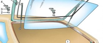
In order to gain access to the main fuse panel of the Lada Kalina, you need to do a number of manipulations:
- On the closing panel, on the left and right, there are grooves that need to be pulled alternately. Also below. This operation should be done carefully so as not to break the plastic fasteners.
Gently pull and remove from the grooves
Gained access to the fuse box
Thus, the fuses and relays of the main unit of the Lada Kalina, as well as the control board, are changed.
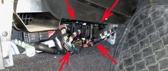
Location of additional fuse box
The additional fuse box is marked with an arrow in the photo.
The additional relay and fuse box for the Lada Kalina is located to the right of the front passenger's feet. It can be accessed by unscrewing the cover bolts and removing it. In order to dismantle this block, unscrew the 3 mounting bolts. The replacement process is carried out in the same way as with the main unit.
- fuel pump activation relay;
- cooling system electric fan fuse (50A);
- cooling system electric fan relay (low speed);
- main relay;
- cooling system fan relay high speed).
Window lifter diagram for VAZ-2115, VAZ-2115
Power windows for front doors for VAZ-2115, VAZ-2114 cars (usually power windows are installed only on front doors).
1 – mounting block; 2 – power window switch for the right front door; 3 – gear motor for the electric window of the right front door; 4 – motor reducer for the electric window lifter of the left front door; 5 – power window switch for the left front door; 6 – ignition switch; K5 – relay for turning on electric windows; A - to power supplies; B - to the external lighting switch.
Key programming instructions for Lada Kalina, Priora, Granta, etc.
- Close all doors. Turn on the ignition with the training key and wait in the on state for at least 6 seconds.
- Turn off the ignition. The indicator light in the warning lamp unit should flash quickly (at a frequency of 5 times per second) while the learning procedure is being carried out correctly. If the lamp stops flashing quickly, it indicates an incorrect operation, an out-of-time interval, or a malfunction. Remove the training key from the ignition switch.
- While the warning lamp is flashing (about 6 seconds), insert the remote control and turn on the ignition. The immobilizer buzzer should emit three beeps. If the buzzer does not sound and the indicator has stopped flashing, this means: - the time interval of 6 seconds has been exceeded and it is necessary to repeat the learning procedure, starting from step 1; -immobilizer is faulty
- Wait 6 seconds for the buzzer to emit two more beeps and turn off the ignition.
- If it is necessary to train the second remote control, then you should perform steps 3...4 again, using the second learning remote control to turn on the ignition. If not, continue from step 6.
- After turning off the ignition for no more than 6 seconds, while the indicator is flashing, remove the remote control, insert the learning key and turn on the ignition. The buzzer should beep three times. Wait 6 seconds until the buzzer beeps two more times.
- Turn off the ignition without removing the training key, wait 6 seconds until the buzzer sounds a single sound signal. The indicator should flash twice as fast. If the sound signal does not sound and the flashing indicator stops, you should return to step 1 and repeat the learning procedure. If a repeated failure occurs when performing step 7, this means that the ECM was previously trained with a different key, in which case the controller should be replaced.
- After the buzzer gives a single sound signal, no later than 3 seconds, turn on the ignition for 2...3 seconds and then turn it off (after turning on the ignition, the buzzer will sound three times and the indicator will stop flashing). The hazard warning lights should flash and the car horn should beep.
- Remove the learning key. Wait with the ignition off for at least 10 seconds. Insert the working key and turn on the ignition. Wait 6 seconds, if the indicator does not flash, test start the engine, the engine should start. If the indicator flashes, turn off the ignition and wait at least 10 seconds. Turn on the ignition. The warning light should not flash and the engine should start. If, after turning on the ignition, after 6 seconds the indicator lights up with a constant light, then the learning procedure must be repeated, starting from step 1.
Parallel connection - diagram
Wires from the main button next to the driver's ESP motor go directly to pin 88 of the relay and from pin 30 directly to the engine, and long wires from the backup button go to pin 85 of the relay winding, and the relay feeds a powerful plus to the passenger's ESP motor. A parallel connection for power buttons is preferable, since there is no need for a relay on the main (passenger) button, thereby eliminating unnecessary relay clicking when the main button on the passenger door is operating.
Restoring Heated Strips
So, the rear window heating does not work, what to do and where to start the repair. The first thing you need to do is get a high-quality repair kit for restoring electrical filaments. You can purchase it at any auto store or car market at a very reasonable price, but not less than three hundred rubles. Kits that are too cheap have low quality materials and simply may not solve the problem.
Scheme for any number of buttons and doors
Here you can place any number of buttons in parallel and simultaneously press them in different directions - a short circuit is impossible from the circuit design. In a situation where we press the up button on the main button, and the down button on the backup button, it will simply stop, since both power lines will have the same potential. The advantage of the circuit is that the power switching is in one place, there are no losses in the harnesses and on the buttons, there is a minimum of “pulling” of wires - 2 in total per channel + ground.
The main reasons for the breakdown of the heated rear window
When the heated rear window fails for some reason and, as a result, it fogs up heavily or becomes covered with ice, this greatly complicates visibility and leads to reduced safety on the road.
To avoid this, it is necessary to eliminate possible breakdowns. Since such a device does not have moving mechanisms, drives or other complex parts, the causes of malfunctions lie only in the electrics.
In normal cases, the glass heating operates while the engine is running. When the corresponding button is pressed, power goes to the relay control contacts, which turn on the power circuit. Thus, the current is distributed along the heating threads glued to the rear window, which are usually attached to the body in the area of the rear pillars.
Based on the above, the most common reasons for the rear window not heating are the following: a faulty relay, damaged heating filament or wires, or a blown fuse. The most common problem is a damaged relay, the contact group inside of which tends to burn and, accordingly, stop passing current. Such a malfunction is detected using a multimeter.
An equally common malfunction is the rupture of heating threads. Since they are applied to the glass with a fairly thin layer of a substance that conducts current, they are quite easy to damage, for example, when removing a tinted coating. Usually only a couple of lines fail, making the problem easy to notice. The functioning of damaged threads can be restored through the use of special adhesives.
But in the event of damage to the wires in the electrical circuit, detecting the break area is quite problematic. You will also have to look for it with a multimeter, checking each wire. The fault must be eliminated using terminals or the usual twisting method.
Finally, before you start looking for the cause of the heating failure, you should check the fuse. If it is in full working order, you can check according to the list above. If the fuse is blown, there may be a short circuit in the vehicle. You will need to replace the element with a new one and check the heating operation. If the new fuse immediately blows, it is necessary to identify the causes of the short circuit.
These are the main reasons for the rear window heating to break down. There may be more of them in different brands of cars. If you cannot identify the cause yourself, you should contact the service.
Glass closer Pandora DWM
Connection diagram for the passenger door button in series through a duplicate button on the driver's door. Contacts 1-6 and 7-3 are always normally closed. When you press the up button, contacts 1-6 open and 1-2 close (window rises). When you press the down button, contacts 7-3 open and 7-2 closes (window down). The 30th contact of a 5-pin relay, without supplying voltage to the winding contacts, is constantly shorted to contact 88, which gives us the necessary negative contact (works like a switch). If voltage is applied to the winding, then contact 30 is disconnected from contact 88 and connected to contact 87. Contact 86 of the winding is connected to ground.
Electrical wiring faults
After installing a new fuse element, you should check the operation of the heater, but when the situation has not changed, you need to diagnose the power supply wires. There is a high probability that they may break, break on the mount or burn out, and as a result, currents will not flow to the heating strips. You can check the condition of the wires as follows: initially switch the heating button to the “on” position, then use a tester to check the presence of voltage at both terminals connecting the wires to the heating tapes. Most often they are located on the sides of the glass or at its bottom. If there is no voltage on the wires, then perhaps this is the reason why the rear window heating does not work. What to do in this case? Trace the entire path of the wiring, which means there is a break. Clean the contacts of the connecting sections and terminals, since during prolonged operation they can simply oxidize and not allow voltage to pass through. If it is not possible to trace the wiring path and detect damage at home, you need to seek the help of an auto electrician.
Installation of electric windows on a VAZ
The procedure is performed in the following sequence:
- temporarily remove the glass seal located on the inside of the door;
- remove the glass, and then dismantle the window regulator fastening mechanism;
- we install devices that will operate from an electric drive;
- connect the negative terminal to the battery and check the operation of the new window regulator;
- We install the glass in place and trim the door.
Unlike conventional mechanical devices, power windows are not equipped with traditional gear reducers, but with a special drum. The shaft of a DC electric motor is inserted into its hole located in the center. In this case, the motor is only a component of the gearmotor, on which, as we found out earlier, the speed and quality of raising and lowering the windows depends.
Installation of the lifting device is quite simple. It starts with disconnecting the battery. After this, use a curved screwdriver to unscrew 3 screws, unfasten the door trim latches and remove the door pocket. Using a thin screwdriver, pry off the handle (latch) of the window lifter - the tip of the tool is inserted into the recess between the latch and the socket.
The handle itself is removed. At the next stage, the car door opening handle is dismantled. To do this, use a screwdriver to pry the handle cover and remove it. Now use a screwdriver to remove the 2 fastening screws that were hidden by the cover plate. After this, the handle can be removed without much difficulty. Using a screwdriver, you can also remove the power window button, which serves to lock the door.
After removing 6 pistons, the trim covering the car mirror adjustment mechanism is also removed. As a result, it remains easy to dismantle the door trim. Armed with a 10mm wrench, unscrew the 2 bolts that hold the auto glass clips. Next, 2 nuts securing the lifting mechanism, nuts of the upper and lower fastenings, and 3 nuts securing the lifting mechanism are unscrewed in sequence.
Upon completion of the described stage, it is time to remove the lower guide pin of the lifting device from the door panel. To facilitate and simplify such an operation, the upper pin of the guide must be bent using a screwdriver. Now the entire lifting mechanism can be safely removed through the resulting opening in the door frame.
Advertisements on NN.RU - Auto
Lengthen Gas 331043, 331063 Valdai-farmer for installation of a body 5.1/6.5 m. The chassis is lengthened by increasing the wheel size.
A specialized company for the conversion of trucks produces extensions for man man, iveco and iveco truck tractors.
Conversion of a cargo-passenger gazelle, an all-metal gazelle, an autoline into a cargo gasel 3302 gas 33023 gazelle-farmer includes c.
We sell KAMAZ injection pump (All types) BOSCH injection pump for KAMAZ 1 year warranty Bosch Euro-3 injection pump 1 0402698817 (electr.) EURO-3 - 134,200 rub. 2. Price: 131,000 rub.
The weather this weekend will not be very pleasant: summer warmth has not yet returned to our region. But neither are cold temperatures with heavy rains.
Imagine, you wake up in the morning, open the curtains, bright sunlight bursts into your apartment, and outside the window is a stunningly beautiful landscape.
An accident occurred in the Moskovsky district of Nizhny Novgorod: a girl was swinging her friend, but the swing suddenly fell. As a result.
Today, Nizhny Novgorod fast food lovers have a real holiday: a new worldwide outlet has opened on the renovated Nizhne-Volzhskaya embankment.
Installing an additional ESP button in the door of a VAZ 2110, 2111, 2112 and operating the ESP without ignition and relay
The content of the article:
ESP operation without ignition and relay for VAZ 2110, 2111, 2112
As we all know, the Internet is full of information on how to wind a wire and make the power windows work without the ignition key, but it seems to me complete nonsense. Let's look into this.
The proposed method on the Internet is this: first of all, we must open our mounting block with fuses and find there the relay responsible for the electric windows.
Having verified it experimentally, namely by turning on the ignition and pulling out the relay, we understand whether the window lifts work or not. If this is what we need, take out the relay.
Then we begin to do some manipulations with the relay by winding wire around it.
I don’t know about you, but I have a question: why do we need this?
We have in our hands an ordinary 4-pin relay, where the principle of operation of the relay is clear to us.
On the Internet they simply suggest that we short-circuit the water contact of the power supply-30 and the output contact of the ESP-87. This will lead to a contact that bypasses the coil (relay), which will only work if it receives power (plus) from the ignition switch (contacts in Relay-85,86-Coil).
So isn’t it easier for us, without making a collective farm, to simply make a jumper to provide power directly?
Make it from a thick wire with a cross-section of 2.5-4 squares so that our jumper does not get hot.
And connect it directly to the block. On the input voltage connector, contact is 30 and output voltage is 87.
Then to turn on the ESP you will not need to turn the ignition key. Since Power (plus) will come to the ESP, bypassing the relay, which will only work when power (plus) is supplied from the ignition switch.
Then there will be no need to farm collectively.
Installation of an additional ESP button in the door of a VAZ 2110, 2111, 2112
I bring to your attention a step-by-step description of the process of installing an additional power window control button (ESP) in the door. The process is not very complicated and time-consuming; everything will take about two hours.
In order to install an additional power window key on the VAZ 2110 door, we will need:
1. 9 meters of wire (I used wires of the following colors: black, yellow, white, 3 meters each) 0.75 mm (section) 2. Button for controlling the ESP (VAZ 2110)* 3. Block for the ESP button 4. Terminals "mother" large - 2 ** 5. Terminals "male" large - 2 ** 6. Terminals "mom" small - 7 ** 7. Terminal "ground" 8mm - 1 8. Blocks for terminals "mother - father" large — 1 (of each type) 9. Plastic clamps (small) — 8 10. Pistons for sprinkling the door trim — 7***
* - in principle, instead of a ten-point rocker button, you can install HIGH-CURRENT (power) buttons from Kalina or Priora, but check with the seller that they are high-current, trigger ones will not work. ** — I didn’t buy these terminals, they came with the pads. *** - they are soft for me, so they didn’t break => I didn’t buy them.
Wiring diagram for the ESP button in the door.
Now we determine the contact numbers on the button and block, according to the diagram:
Okay, we figured it out. The next thing is to find the ESP relay. Typically, the relay is located on top of the mounting block cover. If you have more than one relay installed, then remove them one by one and check if the ESPs are working. The relay, after removing which the ESP stopped working, is the ESP relay.
Diagram and marking of fuses and their replacement
If you turn over the cover of the Lada Kalina fuse box, you can see the markings and which fuse and relay are responsible for what. Also, it can be seen in the vehicle’s service and technical book.
Fuse box diagram
Let us indicate and decipher the fuse number, amperage and what it is responsible for:
F1 - (10) - Instruments: immobilizer control unit, hazard warning switch, instrument cluster. If, when starting the engine, the starter does not turn and the immobilizer icon flashes, then you need to pay attention to this fuse. F2 — (30) — Electric windows. Read more about why window lifts may not work here. F3 - (10) - Hazard warning switch F4 - (20) - Windshield wiper F5 - (25) - Heater, electric power steering control unit F6 - (20) - Horn F7 - (10) - Instrument cluster, interior lighting F8 - (20 ) — Heated rear window F9 — (5) — Side light (right side) F10 — (5) — Side light (left side) F11 — (7.5) — Immobilizer control unit F12 — (7.5) — Low beam (starboard side) F13 — (7.5) — Low beam (left side) F14 — (10) — High beam (starboard side) F15 — (10) — High beam (left side) F16.17 — (10) — Fog lights F18 — (15) — Heated seats F19 — (10) — ABS F20 — (15) — Cigarette lighter F21 — (10) — Reverse lock F22 — (15) — Electrical package control unit F31 — (50) — Control unit electric booster
ESP Kalina block for VAZ 2110
Moderator: Randall
ESP control unit from viburnum for 4 doors!!
Unread message BHyK » Sat Feb 19, 2011 13:24:28
I've been excited about this idea for a long time now. It consists of the following: 1. 4 beet lifters. 2. Electric mirrors. 3. Glass closer. (Interface) 4. And the driver unit itself.
Since the project requires n amount of money, I buy everything a little bit at a time. So far we have purchased plastic armrests, passenger buttons and a driver's unit from Viburnum.
I would like to consult with the connection diagram. Is it possible to connect all this without a Kalina electrical package controller?
Re: ESP control unit from viburnum for 4 doors!!
Unread message by Longenen » Sat Feb 19, 2011 14:09:13
Re: ESP control unit from viburnum for 4 doors!!
Unread message by Randall » Sat Feb 19, 2011 02:52:22 PM
Re: ESP control unit from viburnum for 4 doors!!
Unread message BHyK » Sat Feb 19, 2011 15:35:01
This is a block on the driver's door with ESP buttons and a mirror remote control. The difficulty lies in connecting the 1st, 2nd and 3rd points to the fourth. I saw an article a long time ago where they connected a viburnum unit to only two doors and they didn’t write anything about the Controller (last photo).
I ask the experts to tell me how best to implement my idea?
Re: ESP control unit from viburnum for 4 doors!!
Unread message BORODA » Sat Feb 19, 2011 15:52:10
Re: ESP control unit from viburnum for 4 doors!!
Unread message BHyK » Sat Feb 19, 2011 16:02:15
Re: ESP control unit from viburnum for 4 doors!!
Unread message BORODA » Sat Feb 19, 2011 16:10:27
Re: ESP control unit from viburnum for 4 doors!!
Unread message by Randall » Sat Feb 19, 2011 04:17:14 PM
Re: ESP control unit from viburnum for 4 doors!!
Unread message BORODA » Sat Feb 19, 2011 16:25:16
Re: ESP control unit from viburnum for 4 doors!!
Unread message by Randall » Sat Feb 19, 2011 04:43:10 PM
Re: ESP control unit from viburnum for 4 doors!!
Unread message BHyK » Sat Feb 19, 2011 16:48:10
Re: ESP control unit from viburnum for 4 doors!!
Unread message BORODA » Sat Feb 19, 2011 16:51:54
Re: ESP control unit from viburnum for 4 doors!!
Unread message by Randall » Sat Feb 19, 2011 07:01:33 PM
Re: ESP control unit from viburnum for 4 doors!!
Unread message BHyK » Sat Feb 19, 2011 21:58:56
Re: ESP control unit from viburnum for 4 doors!!
Unread message by Bemrik » Sat Feb 19, 2011 22:04:02
Re: ESP control unit from viburnum for 4 doors!!
Unread message by Randall » Sat Feb 19, 2011 22:27:58
Re: ESP control unit from viburnum for 4 doors!!
Unread message linkor » Sat Feb 19, 2011 22:58:13
Re: ESP control unit from viburnum for 4 doors!!
Unread message Yuriy01 » Sat Nov 19, 2011 17:09:39
Re: ESP control unit from viburnum for 4 doors!!
Unread message from Olezhek » Mon Nov 21, 2011 12:10:19
what successes can be achieved with this block. as they correctly said, it communicates with the electrical package unit via a can-bus, all the power keys for controlling the ESP, mirrors and other things are located in the electrical package unit, there is no other way to make this unit work, because the buttons in it are not power ones. there is almost the same block from viburnum but with power buttons, you can distinguish it by the twist
or this old one
People believe nothing so firmly as what they know least about, and no one speaks with such self-confidence as writers of all sorts of fables - for example, astrologers, fortune tellers, palmists. Religion, superstitions. Michel Montaigne
Steps from “Norma” to “Lux”. Part 1. — Lada Kalina Sedan, 1.6 l., 2006 on DRIVE2
Good day, FRIENDS.
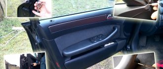
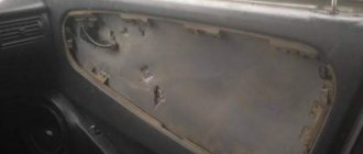
It all started when I broke the passenger rear view mirror. And since I never liked them, this is an excellent reason for Tuning))
I chose mirrors from Granta Liftback, with electric drive, heating, and collars.
Mirrors.
To connect the electric drive I decided to use the ESP control unit from Kalina Lux
ESP control unit
I know that there are extra hemorrhoids, and that it could have been done simpler. BUT! I want to do everything well, as close to standard as possible! Well, rear windows are planned in the near future! But as it turned out, this block communicates with the comfort block via one wire, which is not supported by the comfort block from Norma. I decided to replace the standard block with a block from Lux. They have different connectors, which means you will have to redistribute the contacts. After reading the Internet I found these diagrams.
Comfort Block Diagram Standards
Full size
Luxury Comfort Block Diagram
XP1 1st - ? — New — To the ESP engine of the front-right door. 2nd - ? — New — +/- on all doors. 3rd - Yellow - from pin 14 - To the motors for closing all doors (to all doors). 4th - Orange-Black - New - to the ESP engine of the rear-right door. - No need for a while. 5th - Red-Blue - from the 17th contact - opening the passenger doors. 6th - Black - from the 6th contact - To Ground. 7th - ? — New — to the ESP engine of the rear-left door. - No need for a while. 8th - Blue - from pin 24 - Control of starboard turn signals. 9th - Red - from pin 23 - to terminal 30 (+12V?) 10th - Reserved 11th - ? — New — +/- in the driver’s and rear left door and trunk. 12th - Black - wire from pin 6 - To Ground. 13th - Green-black - New - connect the ESP of the front-left door to the engine. 14th - Blue-Black - from the 16th contact - Control of the left side turn signals. 15th - Red - from pin 23 - to terminal 30 (+12V?)
XP2 1st - Pink-Red - from pin 19 - to the trunk opening motor. 2nd - Reserve 3rd - ? — New — To the power window button of the Rear-Right door. - No need for a while. 4th - White-Black - from pin 25 - Trunk opening limit switch. 5th - ? — New — Passenger mirror up and down. 6th - Red-black - from pin 18 - Opening the driver's door. 7th - Brown-Red - from the 11th contact - Front right door limit switch. 8th - ? — New — Illuminated power window buttons. 9th - ? — New — Passenger mirror left and right. 10th - Red-Blue - from the 15th contact - K-Lin bus. 11th - ? — New — ESP button for the front-right door. 12th - ? — New — ESP button for the rear-left door. - No need for a while. 13th - Gray - from the 5th contact - Heated rear window. 14th - Reserve 15th - Reserve 16th - White-Red - from the 10th contact - Opening the rear doors. 17th - Reserve 18th - Black and White - from the 9th contact - Opening the hood. 19th - Reserve 20th - to the siren - No need.
XP3 - Not used
Attention Questions: - Has anyone ever engaged in such masturbation? Or am I the first to decide on this? — In the diagrams there is a reference to Terminal 30, does anyone know what kind of terminal this is? I'm guessing it's a constant +12V, am I right? — The normal unit is connected to terminal 71 of the ECM/terminal 18 of the APS, but the Lux unit does not seem to be connected to the controller at all, or am I missing something? — The normal unit was connected to the instrument cluster (Terminal 8), but the Lux unit is not connected to the combination at all, do I need to connect it and where? — The standard unit has an output for the rear window heating relay, but the luxury unit does not, will it work? Or how is control implemented in Lux? — If anyone can help with the color palette in the lux connector, I would be grateful
How to check if the window lift motor is working
Kalina. There are cases when the owners of these cars are faced with the problem of non-working power windows. There are quite a few reasons for this defect: a fuse and relay could burn out, a wire could break, a failure in the device’s control unit, or mechanical failure in the mechanism itself.
VAZ 2110. After the necessary checks of the electrical circuit section, making sure that the VAZ 2110 mechanism has stopped working, then the problem may be in it.
It can be fixed as follows: remove the motor, pull out the rotor. Then you need to clean the carbon deposits using sandpaper.
The second problem can be caused by a mechanical effect, which occurs as follows: a buzzing sound after the window has been opened and it remains in place. This problem occurs due to gears. In this case, it needs to be changed, just select the same part.
If you start to close a window and it starts jumping or jerking, it could be warped or debris could get in there. In this case, the parts must be lubricated, and then the adjustable mechanism must be adjusted.
VAZ 2114. There are few reasons for the power window not working on the VAZ 2114:
- Contact connections have oxidized.
- One or more controls are broken.
- Power failure.
In most cases, parts can be repaired, but in extremely difficult situations, all that remains is to replace them with a new device.
Priora. If there is no voltage, then:
- This may be a breakdown of the power window control unit.
- The problem is in the connection of the wires.
- CBKE failure.
Source