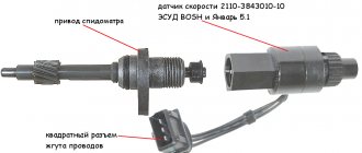
Location of the Chevrolet Niva speed sensor
The standard Chevrolet Niva speed sensor is a separate module designed to transmit a signal from the gearbox output shaft to the speedometer.
The device is simple - the functionality of the system is limited to only one option. The main advantage of the electronic system is increased accuracy. Such a speedometer has a minimal error, which increases traffic safety and eliminates the appearance of controversial fines for speeding.
On the Chevy Niva, the sensitive sensor is made entirely of plastic; the contact chip is also quite sensitive. Therefore, care will need to be taken during repairs.
VAZ-2123 diagram after 2009
Connection diagram of the front wiring harness for Chevrolet Niva VAZ-2123 produced since 2009
Connection diagram for wiring harnesses of the left and right front doors on a Chevrolet Niva VAZ-2123 produced since 2009
Connection diagrams for the wiring harness of the engine management system for the Chevrolet Niva VAZ-2123 produced since 2009
Connection diagram of the instrument panel wiring harness on the VAZ-2123 from 2009
Connection diagram for the rear wiring harness on a Chevrolet Niva VAZ-2123 from 2009
Connection diagram of the wiring harnesses of the left and right rear doors of the VAZ-2123 from 2009
Connection diagram for the additional wiring harness of the tailgate of Chevrolet Niva from 2009
Connection diagram for the seat heating wiring harness for Chevrolet Niva from 2009.
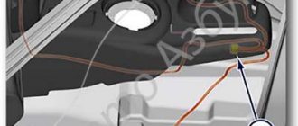
Where is the speed sensor located on a Chevrolet Niva
The DS sits directly on the gearbox housing. It is noteworthy that the location of the device on machines of 2008 and 2022 has not changed. The stability of the structure indicates the correct placement of the device. The module is covered by body panels and the gearbox housing, which makes it inaccessible to obstacles and sharp elements that could damage the sensor.
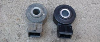
You can see what the module looks like in the photo.
Operating principle and design features
The standard Shnivy speedometer sensor is a hall sensor enclosed in a plastic housing. The element has a specific design that allows it to read the number of shaft revolutions.
The next stage of the device's operation is signal processing. The computer counts the revolutions of the box for a certain period of time and transmits the data to the speedometer display.
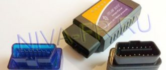
Connection diagram
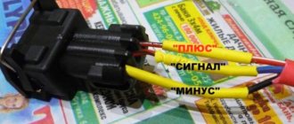
The Shnivy sensor connector itself is a three-pin connector, where:
- red – plus;
- black – minus;
- blue – signal.
The electrical diagram of the element will tell you how the wiring is connected to the speedometer.
Skipping the details and complexity of the speedometer drive pinout, you should focus on connecting the sensor itself. There are three wires here.
- Cable number 1 is a plus, goes to the brake fluid sensor. To maintain constant nutrition.
- The second wire is connected to the speedometer and is responsible for transmitting the signal.
- The third one is black. The cable is responsible for the minus and is connected to another similar wire, or screwed onto the car body, directly at the installation site.
Causes of breakdowns
There are a number of possible reasons for module failure. The most popular of them are described below.
- Mechanical damage. A similar problem occurs among users who operate the vehicle in off-road conditions. Protruding road surface elements, branches and stones can damage the plastic housing or break wires.
- Moisture ingress. Over time, the insulation of wires and blocks can dry out. The winding cracks and allows water to enter the system, which can cause a short circuit.
- System failure. During power surges, the on-board computer may malfunction. Errors within the module prevent data from being read from the device correctly.
Symptoms of a problem
Simply observing the car's behavior will help you understand that the speedometer sensor is not working. Typically the symptoms of a breakdown are factors.
- The speedometer needle jumps, jerks or does not respond. This is due to the complete failure of the device and the need for its immediate replacement.
- Increased fuel consumption. Part of the system is interfaced with the ECU, therefore, the remaining sensors will also act up.
- The speedometer is reporting incorrect data. If a motorist sees that the actual speed of the car differs significantly from the measured one, this is a sign of a device failure.
- 4. Separately, instability of idle speed should be considered. The device is also responsible for the operation of the motor at idle.
Signs, symptoms and causes of faulty sensors in a car.
Good day, dear readers, in this article we will analyze many reasons, but mainly the symptoms of malfunctioning car sensors. Remember that before you go to a service station and panic, you should spend a little time and try to find the cause of the problem yourself and save money.
Signs of a malfunction of the TPS sensor:
— high speeds are possible at idle, this is the most characteristic sign; — a noticeable decrease in engine power and deterioration in throttle response; — when pressing the accelerator there are jerks, dips and twitches; — floating speed at idle; — when changing gears, the engine turns off spontaneously; — overheating is possible; - detonation. (personally, my symptoms were high speeds, inability to brake the engine, jerking, decreased power and, accordingly, increased gas consumption).
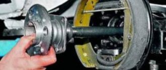
The photo shows very worn tracks
The reasons for the malfunction of the TPS sensor can be: - oxidation of the contacts - you can help in this case, you need to take a special WD liquid and clean all the contacts in the block and under the cover with a cotton swab; — worn sensor substrates if their design included sputtering of a resistive layer; - the moving contact fails - some tip of this contact may break, then scoring will form and other tips will also fail; - the throttle valve does not close completely at idle - in this case, you can slightly file the sensor seats and the throttle valve should close.
The emergency sensor rarely fails, but the average car owner will not be able to diagnose its failure, and some do not know where the sensor is located. The sensor is located opposite the throttle valve.
The check error does not always appear.
Signs of a malfunctioning idle air valve:
— unstable engine speed at idle; — spontaneous increase or decrease in engine speed; — stopping the engine when the gear is switched off; — no increased speed when starting a cold engine; — reduction in engine idle speed when the load is turned on (headlights, stove, etc.).
The idle control valve will not be able to function normally in this state.
The check error does not always appear.
The best prevention for the idle air valve is to periodically remove and clean the idle air valve, usually done in the fall and spring. The valve is located near the throttle valve.
Signs of a malfunction of the mass air flow sensor:
Signs of a malfunction of the air flow sensor or absolute pressure in the intake are characterized by: - Up to 70 degrees the car works more or less well, after 70 an unstable idle begins; — Failures during acceleration and adjustments; — The car sometimes stalls at idle when the gas pedal is sharply pressed; — Increased consumption; — Unpleasant exhaust smell; — Popping noises in the muffler during operation and sometimes popping noises in the intake manifold. (incorrect ignition timing due to faulty sensor)
The air flow sensor is very sensitive and it is not recommended to clean it yourself; the more often you change the filter, the longer it will last you.
The check error only appears when the air flow sensor has stopped working completely, and it can give incorrect readings for a long time.
You can check the air flow sensor or mass air flow sensor by having a multimeter or diagnostic scanner on hand.
Signs of a malfunctioning speed sensor:
— the speedometer does not work or gives incorrect readings; — unstable idling; — increased fuel consumption; - the engine stops developing full power. — the fuel gauge needle reacts almost instantly to fluctuations in the fuel level in the tank, because the computer thinks that the car is not moving and “smoothes” the sensor readings less; — the odometer does not show mileage; sensor in the automatic transmission - when changing speed, the automatic transmission resets itself to neutral, or switches spontaneously in an illogical manner; — the car stops responding to the gas pedal and coasts; — in city driving, when picking up speed, the box sharply increases speed and does not accelerate, does not react to other modes 2 and 1. It seems to only drive at speed 1 but does not slow down with the engine.
How to check the sensor
Usually, if the speedometer needle readings are incorrect, an error from the 0500 level is displayed on the dashboard. Such a code indicates the presence of problems in the module network and indicates the need for diagnostics. There are also possible ways to check the device.
- Check with a multimeter. Connect the positive terminal of the device to the sensor, and the negative terminal to the car body. If nothing happens when the sensor shaft rotates, it is faulty. In the working position, if you spin the wheel faster, the voltage also increases.
- Using a voltmeter. Raise the car on a jack, connect a voltmeter to the DC and spin the free wheel. In this case, changes should occur on the device proportional to the shaft rotation speed.
- A similar technique using control involves attaching a light indicator.
Basic elements of the electrical system
The vehicle's on-board network is designed so that all components and assemblies function smoothly, and control is as comfortable as possible. According to international standards, the voltage is 12V to be compatible with most consumers.
The circuit itself is single-wire. In practice, this means that the “negative” terminal is connected to the car body, and each individual device is powered by a “positive” wire. This greatly simplifies the routing of wires along the body and reduces the number of wires required. It also reduces the likelihood of cable damage and, as a result, a short circuit.
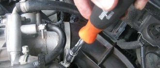
Replacing the speed sensor
Installation does not require deep knowledge of mechanics or specialized, expensive tools. To change the sensor, just follow a simple sequence of steps.
- Drive the car onto an overpass or inspection hole. If such equipment is not available, you can use a jack.
- Disconnect the wiring from the battery and securely secure the machine. In this case, it is recommended to put the gearbox in neutral position.
- Climb under the car and find the DS on the front flange of the transfer case - this is a plastic part connected directly to the device body.
- Using a rag or brush, remove dirt, dust and possible debris from adjacent surfaces that could harm the operation of the new sensor.
- Using a screwdriver, loosen the clamp of the wiring plug and pull it off. In this case, extreme caution should be exercised - the part is quite fragile.
- Use key No. 22 to unscrew the sensor.
- Install the new part in the seat in reverse order.
Malfunctions and replacement of the Chevrolet Niva speed sensor
Vehicle speed has long been one of the indicators that is measured electronically. For this purpose, special devices operating on the Hall principle are used. This is exactly the equipment that Chevrolet Niva cars are equipped with. The device is necessary for the driver to gain full control of the car while driving.
The speed sensor in a Niva Chevrolet car is designed not only to indicate the speed of the car, but also for other actions that you most likely had no idea about.
The speed sensor is involved in the formation of the fuel mixture necessary to maintain higher speeds when driving a car with neutral gear engaged. If you are coasting your car, you can replace that the idle speed is slightly higher than when the car is stationary.
Another function (not for the Chevrolet Niva) is the provision of vehicle speed readings for the electric power steering. As the speed of the car increases, the force of rotation of the steering wheel increases, this is necessary for clearer and more accurate maneuvering of the car.
In older versions of cars, the DC was replaced by a cable, but now this process has become electronic. The article below describes in detail the location, signs of sensor malfunction, testing methods and replacement.
Basic functions of the device.
Each car has a speedometer in its design, which displays the speed of movement of the vehicle.
But the speedometer is only a display of useful information; the main function of indicating the speed of movement is performed by the sensor. If it malfunctions, further travel becomes a pain, especially on city highways, where it is necessary to maintain the speed of movement. Therefore, the main function of the device is to read information about the movement of the vehicle. Indirect functions of the device include:
- possibility of rational fuel consumption;
- regulation of traffic according to road markings and signs;
- makes it possible to regulate speed in order to avoid fines.
To control the speed of movement, a special device is installed on the dashboard - a speedometer. But it only displays the information received, and the speed sensor is responsible for collecting data. If it fails, it will create many dangerous situations on the road, since it will become difficult to control the speed limit in the city and on the highway.
But besides this, thanks to the integration of the electronic control unit into the system, the speed sensor allows you to perform the following functions:
- fuel consumption control
- displaying information on the instrument panel
- in cars with an automatic transmission it is included in the complex responsible for engine control
In case of failure, you are allowed to continue the journey, but this will become difficult.
A speedometer is installed in the design of almost every car. But the speedometer is only a general display that displays information. The main function of indicating speed is performed by the sensor itself. If the device is faulty, further movements become very difficult, if possible at all. The part needs to be replaced as quickly as possible.
The main purpose of the device is to read information related to moving around the city. There are other, so-called indirect functions:
- Adjust speed to avoid fines.
- Simplified traffic following road markings and signs.
- Rational fuel consumption. It is also important for cars produced in 2007.
Without this part, driving a car is possible, but it becomes much more difficult.
Speed sensor location
The DS sits directly on the gearbox housing. It is noteworthy that the location of the device on machines of 2008 and 2022 has not changed. The stability of the structure indicates the correct placement of the device. The module is covered by body panels and the gearbox housing, which makes it inaccessible to obstacles and sharp elements that could damage the sensor.
The sensor itself is a small plastic device that is attached to the shaft area. Inside the case there is a core that transmits impulses to a special controller responsible for displaying information on the instrument panel.
When carrying out work, it should be taken into account that the device can be quite fragile, so installation should be carried out with care.
Causes of sensor failures on Shnivy
There are a number of possible reasons for module failure. The most popular of them are described below:
- Mechanical damage. A similar problem occurs among users who operate the vehicle in off-road conditions. Protruding road surface elements, branches and stones can damage the plastic housing or break wires.
- Moisture ingress. Over time, the insulation of wires and blocks can dry out. The winding cracks and allows water to enter the system, which can cause a short circuit.
- System failure. During power surges, the on-board computer may malfunction. Errors within the module prevent data from being read from the device correctly.
Main types of faults.
Like any car part, the sensor is subject to vibration and is susceptible to contamination and oxidation. Therefore, its failure is possible from time to time. To understand the cause of the breakdown and what to do in each specific situation, the following problems should be eliminated:
- broken wiring
- the appearance of oxide on the contacts
- destruction of wire insulation
- mechanical damage to the housing or its internal components
To do this, you can carry out a certain set of measures to check the condition of the sensor. Typically, such work requires a multimeter. The sensor is removed from the seat. A positive probe is connected to the contacts. The negative one is connected to the ground of the vehicle. The multimeter must be set to minimum power measurement mode. A tube is placed on the sensor shaft and by rotating it an increase in voltage should be observed. If this is not observed, then the sensor is considered faulty.
There is a second diagnostic method. This does not require dismantling the sensor. The car is raised with a jack, then a multimeter is connected to the sensor. To appear, you need to rotate the wheel, observing the readings of the device. If the value does not change, the sensor is faulty.
Signs of trouble
Simply observing the car's behavior will help you understand that the speedometer sensor is not working. Typically the symptoms of a breakdown are factors.
- The speedometer needle jumps, jerks or does not respond. This is due to the complete failure of the device and the need for its immediate replacement.
- Increased fuel consumption. Part of the system is interfaced with the ECU, therefore, the remaining sensors will also act up.
- The speedometer is reporting incorrect data. If a motorist sees that the actual speed of the car differs significantly from the measured one, this is a sign of a device failure.
- 4. Separately, instability of idle speed should be considered. The device is also responsible for the operation of the motor at idle.
Checking the functionality of the sensor
You can check the condition of the sensor using a multimeter in one of two ways. The first time, you will need to turn it off and then remove the device from its location in order to test it. With the second option, it will be enough to jack up the car, connect a multimeter to the sensor and spin one of the wheels. If electromagnetic pulses are detected, one can judge whether the product is working properly.
Instructions for replacing the speed sensor
A broken speed sensor on a Niva Chevrolet car, like on any other, must be removed and replaced with a similar working model. When purchasing, it is extremely important to select a device that is compatible with a specific vehicle model.
- We remove the negative mark from the battery to protect against errors in the computer and short circuits during operation.
- Next, you should examine the bottom of the car to determine where the necessary mechanism is located. Once you find it, the sensor needs to be cleaned of dirt and the terminal with the power wires disconnected. By pressing on the latches, we pull the connector away from the sensor.
- Use a 22mm wrench to unscrew the sensor. If the housing cannot be manipulated, its threaded connection should be lubricated with WD-40, which will facilitate the movement of the housing head.
- Assembly is carried out in reverse order.
Location.
To remove the DS, you need to place the car on a level surface. After this, it is best to disconnect the battery terminals to avoid errors in the BC.
Disconnect the wire terminals; to do this, press the plastic lock on the block. After this, use a wrench to unscrew the sensor from its seat. If you cannot unscrew it immediately, it is not recommended to use excessive force. You need to treat the threaded connection with WD-40, wait a few minutes and continue dismantling.
If during the inspection it turns out that the camshaft position sensor itself has failed, then it must be replaced. As a rule, these units are non-repairable, since their body is sealed and cannot be disassembled. The sensor is inexpensive, and the replacement procedure is simple, and even a novice car enthusiast can handle it.
The sensor replacement algorithm is as follows:
- With the engine not running, disconnect the negative terminal from the battery.
- Disconnect the “chip” from the camshaft position sensor (as when checking).
- Depending on the vehicle model, it is necessary to remove parts that prevent access to the sensor. For example, on modern cars like the Lada Vesta, it is necessary to remove the bracket for auxiliary units.
- Using a wrench, unscrew one or two mounting bolts, depending on the type of fastening. The size of the wrench can be different, usually for VAZs it is a 10 mm wrench.
- After dismantling the mount, you must similarly remove the sensor from its seat.
- Installing a new sensor is performed in reverse order.
- Connect the negative terminal to the battery.
Error P0340 appears on the self-diagnosis system if the crankshaft rotates. Code P0342 - the camshaft electrical circuit shows a low signal and code P0343, accordingly, shows a high signal. It is necessary to check the wiring - for this purpose it is good to use an oscilloscope or other testing device.
Mechanical specialists, even if the sensor is in good working order, still recommend changing it every 4-5 years - such prevention will protect you from breakdowns and accidents, especially since the part is very cheap despite its importance. After all, the semiconductors inside the sensor react poorly to temperature fluctuations - remember your school physics course. There is a special offer on our website
You can get a free consultation with our corporate lawyer by simply asking your question in the form below
There is a special offer on our website. You can get a free consultation with our corporate lawyer by simply submitting your question in the form below.
What to do if the speedometer of a Niva Chevrolet car does not work
Domestic ones have long moved away from the concept of producing completely mechanical components with a minimum amount of electronics.
The modern Chevrolet Niva model is a car with an injection engine, the operation of which is completely under the control of electronics. The article examines the problem of why the speedometer on a Niva Chevrolet does not work. The causes of the malfunction, the symptoms preceding them, and methods for checking all components of the speed counting system will be discussed.
Why the speedometer does not work on the VAZ 2110 injector
All instruments on the VAZ 10 that indicate the speed of the vehicle are pointers, and signs of a malfunction are determined by deviations from the norm of the speedometer needle. If the speedometer is faulty, the arrow when the car is moving:
- does not deviate from zero, that is, does not show speed at all;
- stuck in one position, does not move in any direction;
- jumps, sharply changing readings, while the displayed speed does not correspond to reality.
There are other signs of a faulty speedometer, for example, the device works on a cold engine, and its readings correspond to the norm. As the engine warms up completely, the needle freezes and stops moving.
The main reason why the speedometer on a VAZ-2110 injector does not work is contamination (oiling) of the speed sensor (DS), failure especially often occurs if oil from the gearbox or engine gets onto the DS (for example, there is a leak from the valve cover of the internal combustion engine ). There are also other reasons:
- the speedometer itself has failed;
- the speed sensor is broken (this part on AvtoVAZ cars is not highly reliable);
- there is no normal contact in the DS plug or a break (short circuit) of the wires has occurred;
- The speedometer drive gears installed in the gearbox broke.
Checking the performance of the speedometer 2110
Before you start changing anything, you need to find out why the device does not show speed. First of all, they start checking with the speed sensor, since most often all malfunctions are associated with it. We inspect the DC for contamination, see if there is a break in the wires.
If the electrical part of the sensor is faulty, the Check Engine light on the instrument panel lights up. During computer diagnostics, if the sensor is faulty, the scanner displays error code P-0501, P-0501 or P-0503. Another error is detected by the on-board computer installed on the car.
There are also other signs of a faulty DS:
- at idle, the internal combustion engine is unstable, and the engine may stall at low speeds;
- fuel consumption has increased.
It is quite difficult to check the electrical circuit from the DS to the speedometer on a VAZ-2110 injector car, so here it is better to seek the help of specialists.
The DS drive gears located in the gearbox may also break. The drive itself is easy to check - you need to unscrew the two bolts that secure it with a 10th key and perform a visual inspection of this mechanism.
Principle of operation
The car model in question is equipped with an electronic speedometer. The system includes the following elements:
- A visual speed control device located on the dashboard of a vehicle.
- A set of connecting wires protected by a fuse.
- On-board computer. The device is necessary to receive and calculate electrical impulses for the operation of the entire system.
- EMF or electronic speed sensor. The main purpose of the device is to work together with the gearbox to create electrical impulses.
The electronic speed calculation system was not chosen by chance. This approach made it possible to reduce errors in calculating speed, and also to include this parameter for the distribution of the combustible mixture, for stable operation of the power unit.
The operating principle of the speedometer is simplified as much as possible. The speed sensor is mounted in the lower part of the vehicle's transfer gearbox. It is combined with a mechanical drive. The gearbox drive gear rotates the sensor rod. The rotation is transmitted to a modified Hall sensor. The device converts rotational energy into electrical signals. The number of signals is directly proportional to the distance traveled. For a thousand gear revolutions, about 6004 pulses are issued. These signals are transmitted via a pulse wire to the ECU. The computer calculates the time and number of signals, converts them into electrical voltage and transmits them to the speedometer receiver-drive. Depending on the voltage, the electric motor of the drive deflects the needle of the device by a certain degree, which corresponds to the speed characteristic parameter.
When calculating the speed, the on-board computer also calculates the amount of air for the fuel mixture. The crankshaft position sensor helps with this. This sensor is also pulsed. The calculation of fuel and speed are interconnected, which allows you to most accurately stabilize the number of revolutions of the power unit for the current speed limit.
The operation of the electronic speedometer is often disrupted due to the breakdown of its components. These breakdowns are preceded by certain symptoms, which will be described below.
Device and principle of operation
The operation of the speed sensor on a Chevrolet Niva is based on the well-known Hall effect. It consists in reading by the device the number of electromagnetic pulses generated by the rotation of the motor shaft. This is also a direct answer to the question of where the car speed sensor is located. The placement of the product in the gearbox ensures that it receives the exact number of pulses from which it can easily read the distance traveled.
It is known that one kilometer is equal to 6004 pulses from the shaft, which allows the electronic speedometer to measure the current speed of movement. As the speed increases, the pulse frequency also increases, which is taken into account by the sensor. The device transmits data to the driver to the speedometer, which, thanks to clear markings, allows you to receive information about the speed of the car. At the same time, an insignificant error was found even in the most modern models of the device, but does not exceed 5–7%.
Structurally, the sensor for measuring speed on a Chevrolet Niva is a device made of a plastic or metal case. Its dimensions, comparable to a AA battery, allow the product to be conveniently mounted on the gearbox and connected to the motor shaft. A ferromagnetic core was placed inside the sensor housing, which is responsible for generating electromagnetic pulses when the motor shaft rotates. The device is connected to the on-board speedometer by a conductor that transmits signals from the sensor to its controller.
Symptoms of malfunction
A car owner can visually identify a significant number of symptoms when the speedometer stops working on a Chevrolet Niva. Symptoms include:
- Dashboard signal with error code "P0500". This error indicates a violation of the interaction between the speed sensor and the on-board computer. The reason may lie in a break in the electrical circuit or a malfunction of the EMF itself.
- Error "P0560" indicates high or low voltage in the power circuit. The cause may be a short circuit or a broken connection.
- Speedometer needle. It is very easy to visually determine the malfunction. The arrow completely stops functioning, gets stuck at a certain mark, works with trembling, and shows completely incorrect data. These symptoms may precede a number of malfunctions in the speed counting system.
The described symptoms directly indicate unstable electrical power. There are also several signs that affect the performance of the power unit. These include:
- An order of magnitude increased fuel consumption. The ECU is not able to estimate the current number of pulses from the EMF, since the signals arrive unstably. This is also affected by pulses from the crankshaft position sensor. The on-board computer cannot provide an overall picture of the vehicle speed and engine speed. Therefore, more fuel enters the engine.
- Significantly reduced power. Incorrect fuel dosage leads to a decrease in power. A large amount does not burn completely. The small volume is not enough to maintain the required number of revolutions.
- Failure to operate stable at idle. The reason lies in the periodic shutdown of the IAC (idle speed sensor).
- Complete failure when shifting into gear. Occurs when there is a loss of power. The power unit is not able to shift the vehicle's own weight.
- High load on the power unit. It is especially noticeable in low gears in off-road conditions. May be accompanied by rapid overheating of the cooling system.
These malfunctions are a direct consequence of incorrect calculation of fuel supply, based on inaccurate data from the speed sensor. Next, we will give a detailed overview of the faults that cause the speedometer on a Chevrolet Niva to not work.
What are the types of DS malfunctions?
If this element malfunctions, it is difficult to determine the speed of the vehicle. Photo: avtomarket.ru
In order to promptly fix a breakdown before it develops into a more expensive repair, every owner must listen to the behavior of the car. At the slightest deviation, it is recommended to replace the DS. The main symptoms of malfunctions include:
- Incorrect speedometer readings;
- Fuel consumption increases;
- The engine does not develop full power;
- At idle, unstable operation can be observed.
In this case, each driver will see a Check engine indicator; if there is an on-board computer, error “24” is displayed.
The first thing you need to do is check the condition of the wires and contacts that could simply break. Most often this happens near the connector, where the wires bend and can fray. If the contacts have oxidized or become dirty, they need to be properly cared for. In the area of the exhaust manifold, the integrity of the wire insulation is monitored. In addition, a malfunction of the DS may be associated with a failure of the speedometer cable, which has simply worn out over the years.
How can you test the DS?
Each car owner should know three possible ways to determine the serviceability of the DC; it is necessary to determine whether it produces 12 V. Since the operating principle is based on the Hall effect, the state of the contacts can only be carried out during rotation, and the voltage readings should be within 0.5 V – 10 V.
- Check with a voltmeter. The speed sensor is removed, it is necessary to determine which terminal is responsible for what. One contact of the voltmeter is connected to the terminal that outputs pulse signals, the second is connected to the ground wire. Rotating the sensor, we look at the voltage readings. The faster it rotates, the higher the indicators should be.
- It is not necessary to remove the DS from the car to determine its operation. To do this, you need to lift it with a jack so that the wheel does not touch the ground. Then connect the sensor contacts to a voltmeter, which will give voltage readings when the wheel rotates. If there is a frequency in Hz and voltage, we diagnose that the DS is working.
- It is necessary to disconnect the impulse wire, which is determined by a special controller. As in the previous version, we lift the wheel to rotate it. The “Signal” wire is connected to the control; if the indicator is “-“, then the DS is working. A wire with a light bulb can replace the control in this procedure.
Troubleshooting
Faults are not always related to the part, i.e. The DS may turn out to be quite functional; only some procedures need to be carried out to restore the previous functionality. Photo: drive2.ru
Dirt, dust deposits and oil smudges may form on the DS during the operation of the car. By cleaning this device, you will ensure preventive maintenance of the product and possibly prevent future breakdowns.
The problem may be in the contacts, their fracture, abrasion, and it is necessary to replace the damaged area.
The problem may turn out to be elementary and be hidden in mechanical damage or defects in the cable, which is easier to replace. Having diagnosed the sensor, everyone is convinced that it is not working properly, then it is worth testing and eliminating the above-mentioned malfunctions.
You can learn about some features of speed sensor repair from this video:
Malfunctions
There are not many malfunctions in the speed calculation system. All of them will be described, with detailed guidance on checking and possible replacement of the faults found.
Receiver drive
This unit is located on the back of the dashboard. It won't be difficult to check it. This requires:
- By pressing the button, reset the odometer readings.
- Press this button.
- Turn on the ignition.
When electrical voltage is applied and the odometer is reset, the on-board computer reboots the system, which provokes a check of the car's speedometer and tachometer. Both devices react to this by moving the arrows from zero to maximum. If the speedometer needle has not moved, it is worth checking the power connector. It is red and is located under the panel. Perhaps he does not “sit” well in the nest. After checking, it is worth repeating the test. If the problem persists, you should do the following:
- Connect one end of the control wire to the “+” terminal of the battery.
- Touch the “12” terminal on the red plug several times with the other end. This terminal is the very first, it is the impulse contact of the speedometer.
Relay and fuse box
The mounting block with fuses and relays is mounted on brackets to the left of the steering column and closed with a lid from below. To access the unit, remove its cover by unscrewing the screws.
Mounting block 2110-3722010-08
Mounting block 2110-3722010-01
Mounting block 2123-3722010 since 2009
| № | Current, A | Purpose | |
| 1 | 5 | License plate light lamps Instrument lighting lamps External lighting warning lamp in the instrument cluster Engine compartment lamp Additional brake signal lamp Left side side light lamps | |
| 2 | 7.5 | Low beam lamp (left headlight) Electrical headlight corrector Motorized corrector | |
| 3 | 7.5 | High beam lamp (left headlight unit) Indicator lamp for turning on the high beam headlights | |
| 4 | 10 | Left fog lamp | |
| 5 | 30 | Power window relay Power windows | |
| 6 | 15 | Before 2009: Door lock control unit From 2009: Cigarette lighter | |
| 7 | 20 | Cigarette lighter (Before 2009) Horn relay Horn light Trunk light (Since 2009) | |
| 8 | 20 | Before 2009: Rear window defroster relay (contacts) Rear window defogger element | |
| 8 | 25 | From 2009: Heated tailgate glass element Heated tailgate glass relay Heated outside rear view mirror elements | |
| 9 | 20 | Tailgate heated glass switch (Since 2009) Windshield wiper relay Windshield wiper motor Windshield washer pump Right steering column switch Glove box light Reversing lamps (Since 2009) Headlight wiper relay (contacts; before 2009) Headlight wiper motors (until 2009) Electric headlight washer motor (until 2009) | |
| 10 | 20 | Before 2009: Reserve Since 2009: Electrical accessories remote control unit (door lock) | |
| 11 | 5 | Tail lamps Instrument lighting control | |
| 12 | 7.5 | Low beam lamp (right headlight) Corrector motor gearbox (right headlight) | |
| 13 | 10 | High beam lamp (right headlight) | |
| 14 | 10 | Right fog lamp | |
| 15 | 20 | External mirror control unit Electric external rear view mirrors External mirror control unit | |
| 16 | 10 | Relay-breaker for direction indicators and hazard warning lights (in hazard warning mode) | |
| 17 | 7.5 | Individual lighting lamp Immobilizer warning lamp Brake lamps Additional brake light Interior lighting lamp | |
| 18 | 25 | Before 2009: Reversing lamps Heater fan Windshield washer motor Rear window defroster relay (coil) Rear window wiper relay Rear window wiper motor Rear window washer motor Door lock control unit | |
| 18 | 25 | From 2009: Heater motor switch Heater motor | |
| 19 | 10 | Relay-interrupter for direction indicators and hazard warning lights (in turn signal mode) Instrument cluster (except for the engine management system fault warning lamp) Differential lock warning lamp Starter relay (Since 2009) | |
| 20 | 7.5 | Fog lamps in the rear lights Anti-theft system control unit (Since 2009) Buzzer (Since 2009) | |
| Relay | |||
| K1 | From 2009: Windshield wiper relay Before 2009: Relay for monitoring the health of lamps (jumpers are installed instead of relays) | ||
| K2 | From 2009: Turn signal and hazard warning light relay Before 2009: Windshield wiper relay | ||
| K3 | From 2009: Low beam headlight relay Before 2009: Turn signal and hazard warning light relay | ||
| K4 | From 2009: High beam relay Before 2009: Low beam relay | ||
| K5 | From 2009: Auxiliary relay (Tailgate defroster relay coil, heater fan, windshield wiper and washer, tailgate wiper and washer) Before 2009: High beam relay | ||
| K6 | From 2009: Heated tailgate glass relay Before 2009: Additional relay (Relieves the ignition switch contacts) | ||
| K7 | Heated tailgate glass relay | ||
| K8 | Reserve | ||
Remote relays on the mounting block before 2009:
- Power window relay
- Fog light relay
- Auto horn relay
- Power exterior mirror relay
Remote relays on the mounting block since 2009:
- Fog light relay
- Power window relay
- Seat heating relay
- Horn relay
- Starter relay 2123
Additional fuse block
Additionally, under the instrument panel on the passenger side there are relay blocks with fuses that protect the elements of the injection system.
- Additional relay (turns on the right electric fan through an additional resistor at low rotation speed);
- Fuse (50A) protecting the power circuits of the additional relay and the right electric fan relay;
- Fuel pump (fuel pump) fuse (15A), protecting the power circuits of the electric fuel pump relay;
- Fuse (15A) protecting the constant power supply circuit of the controller;
- Right electric fan relay;
- Left electric fan relay;
- Electric fuel pump relay;
- Main relay 2123 Niva;
- Fuse (50A) protecting the left electric fan circuits;
- Fuse (15A) protecting power circuits switched on by the main relay;
- Controller
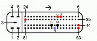
Mounting block connection diagram
The outer number in the designation of the wire tip is the number of the block, and the inner number is the conventional number of the plug. In the diagram K1 is a relay for monitoring the health of the lamps (contact jumpers are shown inside, which are installed instead of the relay); K2 – windshield wiper relay; K3 – relay-interrupter for direction indicators and hazard warning lights; K4 – headlight low beam relay; K5 – headlight high beam relay; K6 – additional relay; K7 – relay for turning on the heated rear window; F1–F20 – VAZ-2123 fuses.
Fuse box diagram from 2022