When your car displays a P0500 code, it means it has detected a problem with the speed sensor (the sensor that reads the car's speed and sends the information to the speedometer).
The speed sensor (DS) is controlled by the electronic control unit (ECU), and when the sensor test ends with an error or no signal, the ECU sets code P0500. Immediately after this, the Check Engine light will come on to alert you to the problem.
Technical description and interpretation of error P0500
This diagnostic trouble code (DTC) is a generic powertrain code. The P0500 code is considered a common code because it applies to all makes and models of vehicles. Although the specific repair steps may vary slightly depending on the model.
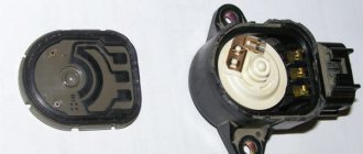
The P0500 OBD2 trouble code indicates that the vehicle speed read by the Vehicle Speed Sensor (VSS) “A” is not as expected. The Vehicle Speed Sensor (VSS) provides information to the ECM (engine control module) about vehicle speed. To display speedometer and odometer.
To do this, it produces a signal of 4 pulses for each revolution of the rotor shaft, which rotates the output shaft through the driven gear. Typically, the VSS is an electromagnetic sensor that uses rotation to transmit a signal to the ECM.
The VSS is installed in the gearbox housing in such a position that impulses from the gearbox can pass in close proximity to it. When the box pulses pass by the VSS electromagnetic tip. Notches and grooves serve to quickly close and interrupt the circuit.
These manipulations are recognized by the PCM as transmission output speed or vehicle speed. This allows us to see the usual display of speed on the speedometer.
Passion around code P0500
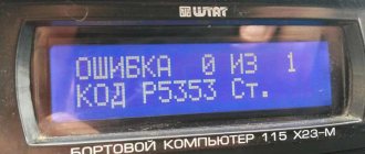
It would seem that what is incomprehensible here? It turns out that everything is clear, but when searching for the fault that generated this code, you can go far. Therefore, I’ll start with how the problem was fixed on a Toyota Avensis car. Code P0500: “The computer does not receive the speed sensor signal.” Happens. But the owner's story makes me think. The last option was to replace the ABS unit. “All the wiring has been checked, the thresholds have been opened”... when you hear this, at first you tense up... because then you can expect anything. Therefore, in order to prevent the client from continuing the story and creating fear, I usually interrupt such a story with a question. Any question can be asked, the main thing is that it is in the vein of the conversation, but interrupts the train of thought and confuses the narrator: - Cover... lid? No. — Okay, it’s the end of the working day, you can leave the car. You'll pick up the car tomorrow.
The check is, in principle, standard for all Toyotas with this code. Described everywhere; by steps, by control points, with data and signal shape.
I use MOTORDATA information, an oscilloscope, a multimeter scanner. Photo 1:
Photo 2:
Photo 3:
Let's start checking, photo 4:
Having checked the errors in the car’s systems with a scanner, I take oscillograms. On the first channel SPD of the ECU, on the second channel SPD of the instrument panel, the third channel is the right ABS sensor, the fourth channel is the left ABS sensor. The car is suspended on a lift, the engine is running.
On channels No. 1 and 2, a reference voltage of 4.6 V is visible, of course there is no signal, the gear is turned off, the wheels do not spin. Photo 5:
We turn on the transmission. The drive wheels begin to rotate. The SPD signal appears on the first and second channels. On 3 and 4 signals from ABS sensors. Sensor signals are primary information about the speed of rotation of the drive wheels. From which, through simple transformations, a speed signal is obtained. And in Fig. 2 everything looks “delicate and noble”, everything works. But does the error come from somewhere?.. here you need to either wait, monitoring the signals, or try to provoke the error to appear.
What caused error P0500 to appear is as follows, photo 6:
The same XX, the gear is engaged, there is a short-term loss of signal from the instrument panel, and, accordingly, to the ECU. And ABS sensors, as you can see, conscientiously perform their assigned duties. I changed the sweep time in this picture so that the moments where the signal is present, where it disappeared and where it reappeared were visible. Here is a pure error P0500. The reason is inside the instrument panel. And it was fixed with a few pokes of a soldering iron. True, you need about. Also, record the oscilloscope data. Then you can look at it carefully. Sometimes you’ll look through it and you’ll find something else that catches your fancy-).
So we continue with the same Avensis... although I didn’t see this error. And the client didn’t mention it. He said that before changing the ABS block, they checked all the sensors and cleaned all the “readers”.
Anyway, while looking at the waveform, I saw something else. Photo 7:
The engine is running, XX, the car is on a lift, the gear is engaged, the drive wheels are rotating. Markers highlight a time period on the pulse sequence of channel No. 3. And it corresponds to the same time period on channel No. 4. Must match. But they don't match. And not only in phase, but also with the amplitude of the signal, not everything is clear either. Only one thing is clear: with such sensor signals that record the speed of rotation of the drive wheels, it should be visually visible that the wheels rotate at different speeds. The fact that the wheels may not rotate at the same speed due to wheel bearings or caliper wedging is understandable. But that's not it. Visually, the drive wheels rotate at the same speed. This means that we need to identify which of the sensors is lying.
From a picture like this, it’s impossible to tell which one is which. Therefore, we will change the picture. Photo 8:
We increase the speed. Now you can see that the ABS ring of the left sensor is “dangling”... but in principle there will be no error. The system will “tolerate” this -).
Well, what if you “anneal”?.. the car is on a lift, the traffic police is not a decree, the “trigger” is on the floor, photo 9:
I don’t change the scan along the way, so the signals from the sensors actually merge and the grid shows that the amplitude is now at least 2 Volts. So far the flight is normal.
We accelerate further, photo 10:
Oops! The signal from the left sensor floated. The right one is normal. And on the left, the amplitude decreased by almost a third. And from the “humps” of the signals it is clear that the time of the periods is different, which means that the speed of rotation of the left wheel has become less and much less... But visually, no-). And the speedometer shows 140 km/h.
Let's look further, photo 11:
And here you can see how it slowly and surely fades, photo 12:
I lowered channel 4 below the background of the right sensor so that it could be seen that there is no signal from the left sensor, but the wheels are spinning, there is an SPD signal, and there is a code for the left ABS sensor Photo 13:
Here the engine reaches idle, the pedal is released and the missing signal appears. If this can be done on a lift, then the same error will definitely appear while moving. It was possible, of course, not to pay attention to this; this is not why the person came. Well, I saw it, well done. Send him, he will return to you. But I'm not a marketer - I'm a techie. And artificially attracting clients is not my bread. Moreover, this method contradicts moral principles. No, this is not a statement: “I don’t need money.” I just consider it humiliating to make money in this way... even if only you know about it. And if I fixed the first fault myself, then to fix this one I resorted to the help of a guy who works as a mechanic. He explained that the ABS ring needed to be put back in place, but it was when the drive rotated that it broke off and rotated on its own. And at high speed, the CV joint on which it was mounted rotated as it should, and the ring, not having “reliable contact with its surface,” simply stopped. And the sensor did not receive a signal about wheel rotation. A wonderful oscilloscope device. Two hits with a hammer on the core - the ABS is fixed -).
When I hired Avensis, a topic was created on the forum specifically for the code P0500. And specifically at Toyota: https://forum.autodata.ru/264/23671/
Well, naturally, I keep an eye on the topics. I don’t particularly interfere anywhere. People advise something. Offers something. There is a usual exchange of opinions. As a result, the topic came to the point where a person fixed the problem... Replacing the ABS unit. Some were frankly puzzled by this... questions followed, but then explanations followed... I “put in my 2 cents too,” but the result was somewhat unexpected, there was some deviation from the topic. When I wrote posts on this topic, I provided the same oscillograms, but did not describe them in such detail, and tried to explain that this code is designated “P” «,
which determines its belonging to a particular system. And ABS fault codes are somehow designated by a different letter -).
I took the computer with me into the car, opened what I needed, everything was in front of my eyes, the information completely satisfied my needs. But, and if suddenly I didn’t find something, then on the same computer there is access to TechDoc, Alldata, Mitchell, but I rarely use the latter. Online access is convenient. And I brought screenshots from Motordata.
Here they are, photo 14:
Photo 15
Photo 16:
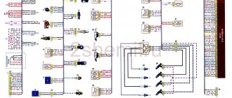
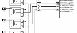
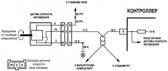
I was brought back to “reality” by posting a fragment of the diagram, photo 17:
The diagram was taken from the forum.
And then came the “horror story”: the 2012 Toyota Coroll HAS CAN! …
And what? ... need to look at the information. I looked. Doesn't change anything. There is CAN, but it has nothing to do with the situation described in the topic. The speedometer on the car worked, the instrument cluster cannot have any influence on the presence or absence of the SPD signal to the engine control unit. The signal still comes from the ABS. The source of primary information was and still is the ABS sensors of the driving wheels. Therefore, when searching for the malfunction that caused code P0500, all possible control points and locations of possible malfunction remained the same. But there is a peculiarity. It lies in the fact that in the ABS block, which processes the signal from the system sensors and transmits it to the control panel, this signal is digital.
Why did they do this? If you look at the fragment of the diagram that was taken from the forum, then even from it it becomes clear that there are design changes in the instrument control panel. The panel collects information about the operation of various systems. In particular, about on/off, etc., etc.... doors, hatch, ashtray -). The goal is to inform the driver.
It is possible, of course, by wire, but in digital form this information is more attractive, since it does not increase the thickness of the harnesses and does not increase the number of connectors. There was some confusion on the forum thread. A story followed about how to watch the SPD signal. It turns out that you also need to connect to the controller’s leg... And here I personally had a question: “What for is a goat button accordion?”
Motordata (https://motordata.ru/ru) gives a comprehensive answer to where and in what places you need to look for a fault with code P0500. Topicstarter, which created the topic and described the problem, went wrong. It was not checked systematically. And replacing the ABS block, which cleared this code, is only a consequence of the fact that a bad contact has been eliminated somewhere. According to the data he posted, the unit worked. Another discussant in the thread took the conversation astray. I posted the oscillograms and for some reason went in the direction of the controller. Even on one channel the guy’s leg was caught. How are we on the forum? If someone wrote: - “CAN…. Either the leg of the protek or the protek” - that’s it, the majority immediately became silent. And they don’t even try to understand what’s written... Let’s summarize:
1. When code P0500 occurs, this code is related to the engine management system. Its meaning is simple: “The ECU does not see the vehicle speed signal.” The reasons are listed, as well as possible locations. Step-by-step search instructions are available.
2. The method for troubleshooting using this code is no different for Toyotas.
3. The speed signal actually passes through the instrument panel (there was a question about this signal: “where does it come from?” There was no clear answer, so I answer:
“All microcontrollers include an analog comparator module. The comparator compares the voltage values present at the two pins of the microcontroller. The result of the comparison is a logical value. Using this value, both an interrupt and a state capture of the counter-timer can be generated. And this allows you to measure the duration of pulses of an analog signal. Therefore, the ECU reference voltage changes from a minimum to a maximum level, forming a pulse sequence containing information about the vehicle speed. And even if one sensor fails, the unit still receives speed information. This signal can be traced in two places at the output of the general purpose port and at the output of the control panel itself.
The timer actually duplicates the operation of the sensors and retains all the information contained in the original signal.”
, photo 18.
4. In cars where information comes to the instrument panel via the data bus (CAN) ... including from ABS, there is a difference: the speed signal from ABS comes to the panel in the form of a digital code. And in the instrument panel, signals from sensors are not compared. But the timer-counter state is also captured. The timer simply generates interrupts using a digital code that contains information about speed. The reference voltage of the control unit will also change amplitude from maximum to minimum level, forming a pulse sequence of the speed signal.
5. The additional elements introduced into the ABS, instrument panel, and data buses are fully controlled. Additional codes C….. and U…… have appeared in the diagnostic system. These codes directly indicate a malfunction in ABS, CAN and the control panel. The appearance of these codes can cause the P0500 code to appear. As an option: replacing the ABS unit and the disappearance of this error is quite understandable. But in this case, the ABS code will be dominant. The same applies to the instrument panel. If the P0500 code is as lonely as “poplar on Plyushchikha,” then there is no need to invent anything, much less cling to the controller’s legs. 6. Considering that data buses are increasingly being used in new cars, it is probably right to start checking by identifying the systems of a particular car, as well as the presence of errors in them. In order not to look for “tomorrow”... it would be more correct to deal with what is today.
7. You should not be skeptical of those who are guided by official information and are inclined to step-by-step verification. There is nothing wrong with this. Although, when I had to deal with this issue, I used Alldata. I opened the 2012 Corolla. And by the time I got to the necessary diagrams, I was grinding my teeth... Well, it’s so detailed that by the time you get to the necessary information... everything is step by step, with pictures.. But it’s hard to make a mistake, though you may not even find the fault -).
And I would also like to note that there are people on the forum who repair cars. And none of us have complete knowledge on this issue. There are fragmentary ones. Some have more of these fragments, some have less. Some people have basic knowledge. This is what needs to be taken into account during discussions. And if a question is asked, it must be answered. Without emotions and grins. Especially if you yourself diverted the topic and provoked these questions. And answering a question with a question is disrespect for the interlocutor. Therefore, in a thread on the forum, I promised that I would answer questions... and I will do it a little later.
We need to figure it out: - are there sensors that generate a digital signal or not; — what is CAN. Why you shouldn’t be afraid of it and how to check it; — is it necessary to go to the controller in search of the desired signal or are standard checks sufficient? - how does a digital signal differ... And how not to confuse it with a regular pulse sequence of rectangular pulses, can it be seen and is it necessary; - about signal conversion from ABS (as a special case) - about fragmented ranks, and why this can cause harm.
To be continued.
Markin A.V.
© Legion-Avtodata
(nickname on the Legion-Avtodata forum - A_V_M) Belgorod, Tavrovo microdistrict 2, Parkovy lane, 29-b.
Tel..
Union of Automotive Diagnosticians
Symptoms of malfunction
The main driver symptom of a P0500 is the MIL (malfunction indicator light) illumination. It is also called Check engine or simply “check light”.
They can also appear as:
- Disables the vehicle's anti-lock brake system (ABS) and traction control system (TCS).
- The warning lights (ABS) or brake lights on the dashboard may come on.
- The speedometer or odometer may not work correctly or at all.
- The vehicle's rev limiter may be lower than normal.
- An automatic transmission may experience problems when shifting gears.
- Other symptoms may be present.
Self-diagnosis
Without going into details of the operation of all electronics, we note that the functioning of all vehicle systems is “monitored” by an electronic control unit (ECU).
It receives information from numerous sensors. Like any computer, the ECU requires software called firmware. This firmware is capable of analyzing indicators received from sensors, comparing them with normal parameters, identifying errors and storing these errors in memory.
Carrying out self-diagnosis
In the Chevrolet Niva, as in some other cars of the VAZ family, some parameters can be displayed on the VDO dashboard. It is often called an integrated on-board computer.
Testing is started by first pressing the daily mileage reset button and simultaneously turning the ignition key.
All instrument needles begin to move, which indicates the beginning of the testing process. Pressing the same button once will cause the firmware version to appear on the display, and pressing it again will give us a reading called an error code.
Panel codes should not be confused with ECU codes, which are diagnosed by external devices.
| Error code | Decoding |
| 1 | Processor faults |
| 2 | No signal from the fuel level sensor |
| 4 | Increased voltage of the on-board network (exceeds 16 V) |
| 8 | Reduced voltage on-board network |
| 12 | Control indicator malfunction |
| 13 | No signal LAMDA probe |
| 14 | Increased coolant temperature |
| 5 | Reduced coolant temperature |
| 19 | Error from HF sensor |
| 21-22 | Error with TPS |
| 24 | Error from speed sensor |
| 27 — 28 | Incorrect CO potentiometer parameters |
| 23 — 25 | Error from intake air temperature sensor |
| 33 — 34 | Error from the MAF sensor |
| 35 | Error from sensor XX |
| 41 | Error from phase sensor |
| 42 | Ignition system malfunction |
| 43 | Error from knock sensor |
| 44 — 45 | Rich/lean fuel mixture |
| 49 | Loss of vacuum |
| 51 — 52 | ROM/RAM errors |
| 53 | No signal from CO potentiometer |
| 54 | No signal from the octane corrector |
| 55 | Load on the power unit |
The operation of the on-board computer cannot be called flawless, since many errors arise as a result of software failure. You have to reset the errors by holding down the daily mileage reset button in testing mode. This diagnostic method is not entirely convenient for the reason that the error code can be the result of the sum of two codes at the same time (10=8+2).
Reasons for the error
A P0500 code may mean that one or more of the following problems have occurred:
- The Vehicle Speed Sensor (VSS) "A" is not reading properly and therefore has insufficient readings.
- A broken or worn wire leading to the vehicle speed sensor.
- Poor connection in the Vehicle Speed Sensor (VSS) circuit.
- The vehicle's PCM is not correctly configured for the actual tire size being used.
- Damage to the speed sensor drive gear.
- The engine control module (ECM) may be faulty.
Error codes VAZ 21214 injector decoding
If there is no on-board computer, you can read the error codes using self-diagnosis. To do this, press the odometer button and turn on the ignition. The speedometer needle will begin to rise to the top; by pressing again, information about the firmware will appear on the screen, and by pressing again, all existing errors will appear.
Controller BOSCH M7.9.7 (euro-2, euro-3)
Table (list) of error codes:
0102 - Low signal level of the mass air flow sensor (MAF). 0103 - High signal level of the mass air flow sensor (MAF). 0112 - low signal level of the intake manifold temperature sensor (ITM). 0113 - High signal level of the intake manifold temperature sensor (ITM). 0116 — The signal from the coolant temperature sensor (DTOZH) is out of the permissible range. 0117 - Low signal level of the coolant temperature sensor (DTOZH). 0118 — High signal level of the coolant temperature sensor (DTOZH). 0122 - Low signal level of the throttle position sensor (TPS). 0123 - High signal level of the throttle position sensor (TPS). 0130 — Incorrect signal from oxygen sensor No. 1 to the converter. 0131 — Low level signal from oxygen sensor No. 1 to the converter. 0132 - High level signal from oxygen sensor No. 1 to the converter. 0133 - Slow response to enrichment or depletion of oxygen sensor No. 1 to the converter. 0134 - Lack of signal (open circuit) of oxygen sensor No. 1 to the converter. 0135 - Malfunction of the oxygen sensor heater circuit No. 1 to the converter. 0136 - Short circuit to ground in the oxygen sensor circuit No. 2. 0137 - Low level signal from the oxygen sensor No. 2 after the converter. 0138 — High level signal of oxygen sensor No. 2 after the converter. 0140 — No signal (open circuit) of oxygen sensor No. 2 after the converter. 0141 - Malfunction of the heater circuit of the oxygen sensor No. 2 after the converter. 0171 - The fuel supply system (air-fuel mixture) is too lean. 0172 - Fuel system (air/fuel mixture) too rich. 0201 — Open circuit for controlling the injector of the 1st cylinder. 0202 — Open circuit for controlling the injector of the 2nd cylinder. 0203 — Open circuit for controlling the injector of the 3rd cylinder. 0204 — Open circuit for controlling the injector of the 4th cylinder. 0261 - Short circuit to ground in the 1st cylinder injector control circuit. 0262 - Short circuit to the source of the on-board network of the injector control circuit of the 1st cylinder. 0264 - Short circuit to ground in the 2nd cylinder injector control circuit. 0265 - Short circuit to the source of the on-board network of the injector control circuit of the 2nd cylinder. 0267 - Short circuit to ground in the 3rd cylinder injector control circuit. 0268 - Short circuit to the source of the on-board network of the injector control circuit of the 3rd cylinder. 0270 - Short circuit to ground in the 4th cylinder injector control circuit. 0271 - Short circuit to the on-board power source of the 4th cylinder injector control circuit. 0300 - Random/multiple misfires detected. 0301 - Misfire detected in cylinder No. 1. 0302 - Misfire detected in cylinder No. 2. 0303 - Misfire detected in cylinder No. 3. 0304 - Misfire detected in cylinder No. 4. 0327 - Low signal level of the knock sensor (DS) . 0328 - High signal level of the knock sensor (DD). 0335 - There is no signal from the crankshaft position sensor (CPS). 0336 - The signal from the crankshaft position sensor (CPS) is outside the permissible limits. 0337 - Short circuit to ground in the crankshaft position sensor (CPS) circuit. 0338 - Open circuit of the crankshaft position sensor (CPS). 0340 - Malfunction of the camshaft position sensor circuit (DPRV). 0342 - Low signal level of the camshaft position sensor (DPRV). 0343 - High signal level of the camshaft position sensor (DPRV). 0422 — The efficiency of the neutralizer is below the permissible threshold. 0441 — Incorrect air flow through the valve. 0443 — The canister purge valve control circuit is faulty. 0480 - Cooling fan no. 1 relay control circuit malfunction. 0481 - Malfunction of the cooling fan relay control circuit No. 2. 0500 — Incorrect vehicle speed sensor signal. 0503 — Intermittent signal from the vehicle speed sensor. 0506 - Low idle speed (idle speed control blocked). 0507 - High idle speed (idle speed control blocked). 0560 — The on-board network voltage is below the system operability threshold. 0562 — Reduced voltage of the on-board network. 0563 — Increased voltage of the on-board network. 0601 - Controller ROM checksum error. 0603 — Error writing/reading external RAM of the controller. 0604 — Error writing/reading the internal RAM of the controller. 0615 — Open circuit in the starter relay control circuit. 0616 - Short circuit to ground in the starter relay control circuit. 0617 - Short circuit to the source of the on-board network of the starter relay control circuit. 1135 - Malfunction of the heater circuit of the oxygen sensor No. 1 to the converter. 1140 — Incorrect signal from the mass air flow sensor (MAF), the measured load parameter differs from the calculated one. 1141 - Malfunction of the heater circuit of the oxygen sensor No. 2 after the converter. 1386 - The test pulse or controller knock channel integrator is outside acceptable limits. 1410 - Short circuit to the on-board power source of the canister purge valve control circuit. 1425 - Short circuit to ground in the canister purge valve control circuit. 1426 — Open circuit for controlling the canister purge valve. 1501 - Short circuit to ground in the control circuit of the electric fuel pump relay. 1502 - Short circuit to the on-board power source of the electric fuel pump relay control circuit. 1509 - Overload of the idle air control control circuit (IAC). 1513 - Short circuit to ground in the idle air control control circuit (IAC). 1514 - Short circuit to the on-board power source (or open circuit) of the idle air regulator (IAC) control circuit. 1541 — Open circuit in the control circuit of the electric fuel pump relay. 1570 - No response from the car anti-theft system (ATS) or open circuit. 1602 — Loss of on-board power supply voltage in the controller. 1606 - Invalid rough road sensor signal. 1616 - Low level of rough road sensor signal. 1617 - High signal level of the rough road sensor. 1640 — Error writing/reading the internal flash RAM (EEPROM) of the controller. 1689 — Incorrect code values in the controller fault memory.
How to Troubleshoot or Reset Trouble Code P0500
Some suggested steps to troubleshoot and fix the P0500 error code:
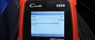
- First, read all stored data and error codes using an OBD-II scanner.
- Then clear the error codes and test drive the vehicle to see if there is a problem.
- Next, check the vehicle speed sensor and all related wires for wear or damage.
- Also check for the presence of a speed sensor signal while the car is moving using a scanner.
- If the above problems do not exist, check the vehicle speed sensor voltage using a multimeter.
Chevrolet Niva error reset
The standard procedure for resetting the controller occurs only after all faults have been completely corrected, otherwise annoying encryption will appear again. The procedure is performed in two available ways.
- Disconnect the battery from the on-board network for 10-15 minutes. The controller will completely reboot and return to factory default settings.
- In the BC menu, enter the “errors” service, press the daily mileage reset button and wait for the sound signal from the car, and horizontal lines should appear on the display.
Diagnosis and problem solving
The first step is to look for Technical Service Bulletins (TSBs) for your specific brand of P0500 vehicle. If the existing problem is not described, following the instructions can help you save time and money in diagnosing and fixing the problem.
Visually inspect all wiring and connectors leading to the speed sensor. Carefully inspect for any abrasions, exposed wires or breaks. Also look for melting or other damaged areas. Repair if necessary.
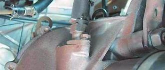
The location of the sensor depends on your car; it is not always installed in the box. It may be located on the transmission rear axle or wheel hub (brake) assembly.
If everything is in order with the wiring and connectors, then check the voltage at the speed sensor. Again, the exact procedure will depend on your car make and model. Most likely this is where the problem lies, so replace the sensor.
Chevrolet Niva error diagnosis
The most reliable way to identify what is wrong with a car is to diagnose electrical appliances and equipment. The procedure allows you to accurately identify breakdowns and quickly repair your car.
There are two ways to detect a problem in a car.
Self-diagnosis VAZ 2123
The simplest procedure allows the motorist to independently identify the damaged area and repair the damage. Thanks to the successful firmware of the on-board computer, some errors are displayed on the standard display. In this case, nothing happens on its own - you will need to perform several steps manually:
- turn off the engine and turn off the ignition;
- find the daily mileage reset button on the dashboard and press it;
- at the same time turn the key in the starting cylinder;
- if everything is done correctly, all the indicators on the dashboard will light up, and the instrument arrows will make a full circle and return to their place;
- at the same time, the firmware version of the on-board computer will be reflected on the built-in display;
- The next press of the key will display a network error.
If the manipulations are correct, one of the indicated codes will appear on the display, and each Niva Chevrolet error number will be responsible for its own section of the highway:
- 0 – error 0 Niva Chevrolet indicates that there are no problems in the on-board circuits; most likely, the breakdown is purely mechanical in nature;
- 1 – standard error of the Niva Chevrolet ECU – the processor is not working correctly;
- 2 – for a Chevrolet Niva, error 2 indicates a lack of power to the gas tank float;
- 4 – malfunction of the battery or generator; a critical excess of the rated voltage of more than 16 volts was detected in the on-board circuits;
- 8 – has the opposite meaning; on a Chevrolet Niva, error 8 indicates an excessive voltage drop in the wiring due to a deep discharge of the battery or a malfunction of the generator;
- 12 – error 12 Chevrolet Niva reports a breakdown of the control indicator;
- 13 – signal transmission from the lambda probe is disrupted, you need to check the device and main power lines;
- 14 – on Niva Chevrolet, error 14 indicates a critical antifreeze temperature, the system requires cooling, otherwise the power unit may boil;
- 15 – the motor is too cold for normal operation, usually the error disappears after a good warm-up or replacement of the sensor;
- 19 – malfunction of the DPKV, the encoding indicates an incorrect speed of rotation of the unit;
- 21/22 – the throttle position differs from the calculated values up/down;
- 23/25 – the air mixture on the intake manifold is excessively cooled or overheated;
- 24 – open circuit of the speedometer, accompanied by a lack of response of the instrument needle to the driver’s manipulations;
- 27/28 – incorrect display of the actual amount of exhaust from the calculated value;
- 33/34 – Mass air flow sensor, the indicators of the device are overestimated or underestimated, relative to the actual state of the system;
- 35 – incorrect operation of the engine at idle, you need to check the correctness of the mixture formation settings;
- 41 – the phase distribution sensor or DPRV has detected an open circuit or the data received is erroneous;
- 42 – multiple misfires were detected, the system turned off the fuel supply to the damaged cylinders;
- 43 – the detonation channel sensor generates an error;
- 44/45 – fuel mixture is too rich/lean; you need to check the fuel lines for mechanical damage;
- 49 – the vacuum gauge is out of order or overloaded;
- 51 – ROM has failed, or there is a breakdown in the power cables;
- 52 – RAM is not working correctly, damaged, no power;
- 53 – the adsorber purge valve is faulty;
- 54 – octane corrector controller is de-energized or broken;
- 55 – the calculated load on the internal combustion engine differs from the established one;
- 61 – the oxygen quantity controller in the intake system transmits incorrect data to the computer.
At the same time, you need to accurately understand that, for example, when error 10 is on the display, the Chevrolet Niva tells the driver that there are several problems (standard, unambiguous codes are summed up).
You should also know that Niva Chevrolet self-diagnosis errors do not reflect the exact location of the breakdown. Codings can only show the section of the wiring where you need to look for the cause of the malfunction. Also, these encryptions may be the result of a software failure after an unsuccessful wash or disconnection of the battery. To obtain more accurate data, the user needs to connect a special diagnostic scanner.
On which cars is this problem most common?
The problem with the P0500 code can occur on different machines, but there are always statistics on which brands this error occurs more often. Here is a list of some of them:
- BMW (BMW X5)
- Chery (Chery Amulet)
- Chevrolet (Chevrolet Captiva, Epica)
- Chrysler
- Citroen (Citroen C4, C5)
- Daewoo (Daewoo Matiz)
- Dodge (Dodge Caravan, Stratus)
- Fiat (Fiat Ducato)
- Ford (Ford Mondeo, Transit, Fiesta, Focus, Fusion, Explorer)
- Honda
- Hover
- Hyundai (Hyundai Porter, Santa Fe, Sonata, Elantra)
- Infiniti
- Isuzu
- Jeep
- Kia
- Land Rover (Land Rover Range Rover)
- Lexus (Lexus lx470, rx300, rx330, rx350)
- Mazda (Mazda 3, Mazda 6, Demio, Premasi, Familia, MPV)
- Mercedes (Mercedes Sprinter, w203, w210, w211)
- Mitsubishi (Mitsubishi Karizma, Lancer, Pajero, Tsediya)
- Nissan (Nissan Almera, Maxima, X-Trail)
- Opel (Opel Antara, Astra, Vectra, Zafira, Meriva, Omega)
- Peugeot (Peugeot 206, 207, 307, 308, 607, Boxer, Partner)
- Renault (Renault Logan, Megan)
- Subaru (Subaru Outback, Impreza, Legacy, Tribeca, Forester)
- Suzuki (Suzuki Grand Vitara, sx4)
- Toyota (Toyota Avensis, Auris, Venza, Vista, Vitz, Kaldina, Camry, Carina, Corolla, Crown, Land Cruiser, Mark 2, Platz, Prado, Premium, Rav4, Celica, Fielder, Funcargo, Highlander, Hilux, Harrier, Chaser , Echo, Yaris)
- Volkswagen (Volkswagen Transporter)
- Volvo (Volvo s60)
- VAZ 2105, 2107, 2110, 2112, 2114, 2115
- Gazelle
- Lada Granta, Kalina, Largus, Niva, Priora
- UAZ Bukhanka, Patriot
You can sometimes encounter other errors with the P0500 fault code. The most common are the following: P0036, P0056, P0102, P0130, P0136, P0325, P0444, P0501, P0502, P0503, P0505, P0600, P0700, P0717, P0720, C1408, U1113.
Diagnosis P0500
The following steps will help you resolve the P0500 code.
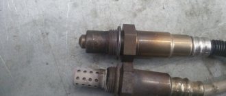
Inspecting the Sensor and Connections
Many problems can be easily found in the harness and connectors. Begin diagnostics by visually inspecting the sensor and its connections.
Check the DS using a diagnostic tool
Connect a diagnostic tool or adapter and view real-time data. Monitor the speed readings as you drive and see if they match your speed. To do this, you can use the Torque program.
If the readings do not match your actual speed, there is something wrong with the sensor or its circuit. If the readings match but the P0500 code does not go away, you likely have an intermittent fault.
Check sensor output
If the car has not passed the tests listed above, then it’s time to determine which part of the DS circuit is at fault. The testing process is slightly different depending on the type of sensor.
Reed sensor
To test the reed switch, turn the speedometer cable or wheel and use a multimeter to see if the circuit opens or closes.
Permanent magnet sensor
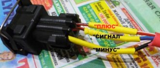
The permanent magnet sensor can also be tested using a multimeter. Remove the connector and connect the device to the sensor terminals.
Most DS should show values between 190 and 250 ohms , but it is recommended to refer to the manufacturer's specifications for exact information.
Naturally, if the multimeter shows “OVER”, “OL”, or “1”, then the sensor should be replaced.
Then raise the car. Rotate the wheels and watch the ohmmeter - the readings should fluctuate. This can also be done with a multimeter set to read alternating voltage (AC). If the readings do not change, the sensor is faulty and must be replaced.
Hall effect sensor
Using information from the repair manual, determine which terminal on the sensor connector is the signal return wire. Using a multimeter in DC voltage mode, check the sensor return wire.
Connect the black test lead of the multimeter to the battery negative. As you turn the wheels, you should see the voltage reading on the meter change.
Checking the speed sensor with an oscilloscope
Although a multimeter can be used to test speed sensors, it is much better to test them using an oscilloscope. It allows you to view the sensor waveform and check for inconsistencies.
The magnetic sensor produces a variable sinusoidal waveform. The Hall effect sensor produces a square waveform. This signal never falls below the zero point.
Check speed sensor circuit
If you have checked the speed sensor and the P0500 code is still present, you need to check the sensor circuit.
Checking the Reed Switch Circuit
The reed switch circuit is quite simple. The sensor will have two wires going to it: power and a return signal to the ECU. Check your vehicle's repair manual to determine which wire is which.
- Set the multimeter to DC voltage measurement mode. Connect the red lead of the multimeter to the power pin on the connector and the black lead to ground. In most cases you should see around 5 volts.
- Then check the continuity of the circuit to the control unit. This can be done by touching one test lead to the return signal contact on the sensor connector, and the other to the signal contact on the ECU. Set the multimeter to measure resistance ("Ohms") - a value should appear on the screen. If instead the device shows “OL” or “1”, then you have an open circuit.
Checking the System Status
Problematic components in this case may be the speed sensor (on front-wheel drive vehicles it is installed on the hub bearing, on rear-wheel drive vehicles - on the gearbox or differential), the instrument panel (panel, its electronic part), the on-board control system (ECM in the English abbreviation). Before checking, it is advisable to make sure that the speedometer in the car is working correctly. It’s easy to verify this by taking a short trip.
If error code P0500 occurs, you must do the following:
- Using special diagnostic equipment, it is checked whether the speed sensor is working properly. If the appropriate equipment is not available, then you can install a known working sensor of a similar model on the machine.
- Using a multimeter, check whether the circuit between the sensor input signal and its ground or power wire is closed (often, it is due to insulation failure that a short circuit occurs in the circuit, and, accordingly, incorrect operation of the sensor and the entire system).
- Using a diagnostic tool, find out whether the forming voltage from the sensor arrives several times per second along the signal cable. Moreover, the connection may be interrupted for the first few seconds, but then restored again.
- The connection between the sensor and its ground is checked.
- If the sensor is four-wire, then the integrity of the fourth wire is also checked using a multimeter.
Please note that when starting and stopping the car in place, the connection with the sensor is interrupted, but is restored immediately while moving. Therefore, the verification process is performed according to a certain algorithm.