Due to a malfunction of the ignition module, the following malfunctions may occur in the operation of the injection engine of VAZ 2108, 2109, 21099 cars: the engine “triples”, “doubles” (works or tries to start on two cylinders), unstable idling, “dips”, “jerks” , “twitching”, etc.
— Multimeter, autotester or other device with ohmmeter and voltmeter modes
— Socket wrenches or heads for “13” and “17”
Preparatory work
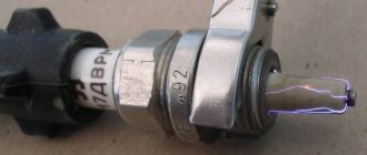
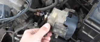
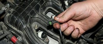
— Remove the ignition module from the engine
Disconnect the ends of the high-voltage wires. Use a key set to “13” to unscrew the two upper fastening bolts, and use a key set to “17” to loosen the tightening of the bottom bolt. Remove the module along with its bracket.
— Cleaning from pollution
Wipe with a dry cloth.
The procedure for checking the ignition module (coil) of the ignition system of VAZ 2108, 2109, 21099 cars with an injection engine
In garage conditions, you can check the secondary windings of the ignition module for an open circuit and the primary windings for a short circuit, as well as the voltage supply to the module from the ECU. This is quite enough to diagnose the problem.
— Check for short circuit
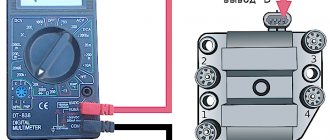
The positive probe of the multimeter in ohmmeter mode to terminal “D” of the ignition module connecting block, the negative probe to the bracket (“ground”). If there is no short circuit, the device readings tend to infinity.
— Check for “break”
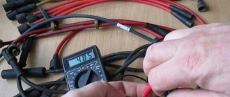
Using a multimeter in ohmmeter mode, we alternately measure the resistance between terminals “1” and “4”, “2” and “3” of the ignition module.
The resistance for each measurement should be within 4 kOhm. If it is different or does not correspond to the required indicator, the module should be replaced.
— Checking the voltage supply to the ignition module
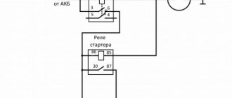
If previous checks did not reveal a malfunction, you need to check the voltage supply to the ignition module. Turn on the ignition. Using a multimeter in voltmeter mode, measure the voltage between terminals “C” and “D” of the block of the wiring harness going to the module (the terminals are marked on the block itself). The voltage must be within the vehicle's on-board voltage (12V). If it is smaller or absent, then the battery may be discharged, the wires from the computer to the ignition module are faulty, or the control unit (ECU) is faulty.
Notes and additions
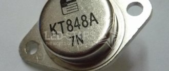
— Often, one of the visual signs of failure of the ignition module can be two wet and two working spark plugs, since the module consists of two pairwise connected ignition coils that alternately produce a spark in two cylinders -1-4, 2-3. The failure of one of the coils leads to the engine running (or trying to start) on two spark plugs.
— The problems listed above in the operation of a car engine may be based not only on a malfunction of the ignition module, but also on a malfunction of the spark plugs, high-voltage wires, as well as the power and control system (ECM).
More articles on the ignition system of the injection engine of VAZ 2108, 2109, 21099 cars
Comparative test repair
Ignition of gasoline in the cylinders of an internal combustion engine occurs using a spark generated by the ignition system. The ignition module is the main element of the system, creating a spark on the spark plugs using high voltage. Each car manufacturer develops and produces its own original module, but the principle of its operation is the same for all devices. During operation, deviation from the specified parameters or breakdown of the ignition module negatively affects engine operation until the power unit fails.
Purpose and principle of operation
Ignition module VAZ 2110
The ignition module of a modern car performs the function of generating high voltage to produce a spark at the spark plugs. It consists of two coils with a closed magnetic circuit and a two-channel switch. Sometimes the switch is made as a separate device, but in most cases it is combined with an electronic control unit for the engine. Externally, the modules differ in the number of wires in the connection connector: a module with a switch has 4 wires, and paired coils have 3.
The ignition module is controlled by the ECU, which supplies constant voltage in the form of low-voltage control signals to the windings of its coils at the right moment. The end of the signal is the beginning of the spark. Thanks to magnetic induction, at the moment of application, a high voltage is generated, creating a spark at the spark plug. The device is located in the engine compartment and can be easily identified by the high-voltage wires leading to the spark plugs.
Operating principle and location
The ignition module is controlled by a controller, which in turn receives information about the state of the vehicle from various sensors (IAC, mass flow sensor and others). The controller also sets the sequence of operation of the ignition coils or, in other words, regulates the supply of current to the spark plugs. The ignition module operates at temperatures from -40° to +130°.
Finding its location is not difficult; high-voltage wires (HV) go from the module to the spark plugs; along them you can find the module.
Signs of a malfunctioning ignition module
A malfunction of the ignition module is determined by the following symptoms:
- Difficulty starting a cold engine due to lack of spark on one or more spark plugs.
- Floating engine speed at idle is a situation in which the speed changes without any action on the part of the driver.
- Dips in power, which manifests itself during acceleration and driving up a long climb.
- Decrease in engine power.
- Cylinders 1-4 or 2-3 do not work (engine “troits”).
- Indication of the “Check Engine” indicator.
Symptoms of malfunction
More often than not, the bobbin does not suddenly fail. This is usually preceded by a number of warning symptoms.
The main symptoms of a faulty ignition coil:
- misfires in one or more cylinders, they can be determined using a scanner by the presence of the “triple” effect of the engine;
- the appearance of “breakdown tracks” on the housing can be determined visually when starting the engine in the dark;
- the occurrence of cracks and chips in the dielectric zone;
- overheating of the structure;
- burning of rubber tips of high-voltage wires;
- oiling, contamination.
If the above symptoms appear, you should consider purchasing a replacement device. You can't stand by and watch an ignition coil die. In the event of a sudden coil failure, further independent movement will be impossible (unless you have individual coils installed).
Ignition coils
Possible causes of ignition module malfunction
Despite the high reliability and durability of the ignition module, during operation it can fail, like any other mechanism. Among all possible causes of breakdowns, in 9 out of 10 cases the following occur and are diagnosed:
- Use of inappropriate components in the ignition system. High-voltage wires are selected based on the parameters of the module, since excessively high or low voltage creates malfunctions or burns out contacts.
- Defective or damaged parts, poor quality assembly. Defective components break down faster and damage other components or elements of the system. Practice shows that the selection of high-quality components and their periodic diagnostics allow the module to remain operational for a long time.
Connection diagram
The ignition module is part of the space under the hood, it’s easier to find it by the position of the high voltages, they go from the spark plugs straight to it.
Ignition coil diagram:
VAZ 2114 ignition coil diagram
This diagram is good to follow when you have to replace the ignition coil of a VAZ 2114. In principle, everything is transparent: from contacts with the controller (ECU) to high-voltage wires. The name of the circuit is often common under the name ignition coil pinout: the pinout is a visual representation of the functionality of the device's contacts, which are numbered according to their purpose.
It can be connected in two different ways: when the ignition system coil is removed and when it is directly in its place in the car engine.
If you are holding the module in front of you:
- Let us recall the diagram: the first and fourth contacts are on one winding, the second and third – on the other (they are numbered in the diagram!)
- Then, the lower explosive contact (left) goes to the first cylinder
- On the second - upper explosive contact (left)
- The third cylinder goes to the upper explosive contact (right)
- On the fourth – lower explosive contact (right)
If the module is plugged into the engine, then pinouting the explosive contacts will be more difficult, because the device stands at an angle (as if in a diamond):
- We throw the central lower contact onto the first cylinder
- On the second - left contact
- We put the upper contact on the third cylinder
- On the fourth - right contact
Of course, the first installation option is more convenient, especially since the explosive wires require increased care in the nature of the connection (mixed up and won’t start, in the worst case, the entire engine system is ruined). Speaking to the point, it is clear that the connection diagram for the VAZ 2114 ignition module is not complicated.
By the way, buying an ignition coil is not a cheap pleasure; the price of an ignition module for a VAZ 2114 ranges from seven hundred to a thousand rubles, depending on the location of your city on the map of our country (for more information about how much an ignition module for a VAZ 2114 costs, you can find out by calling a disassembly service or a spare parts store, the running part is almost always in stock).
Checking the ignition module
Checking the ignition module for functionality is carried out in the following ways:
Replacing the ignition module with a known good one
1. The easiest way is to connect a known working module. In this case, the devices must be completely identical, the high-voltage wires are in good condition, and the reliability of the contacts has been checked.
Checking the contacts on the ignition module
2. Moving the module, which allows you to identify unreliable contacts. To do this, move the wire block and the module itself. If during exposure the engine reacts by changing its operation, then the cause of the problem lies in poor contact.
Measuring resistance at the terminals of the ignition module
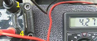
3. Resistance measurement. To do this, you will need a tester switched to ohmmeter mode. Measurements are carried out on the paired terminals of the module between cylinders 1 and 4, as well as cylinders 2 and 3. The resistance value should be the same and approach 5.4 kOhm.
Checking the ignition module using a tester
4. Check the voltage with a tester. One probe of the device is applied to contact A of the block, the second to ground. After turning on the ignition, take readings from the device. If the wire is in good condition, it will show a voltage of 12 V; if it is missing, check the fuse protecting the ignition module. Then check the continuity of the circuit with a 12 V test lamp. Apply one end of the wire to contact A and rotate the starter. If the lamp does not blink, the circuit is broken. The procedure is repeated in a similar way with other contacts.
Diagnostics of the ignition module with professional equipment
5. Diagnostics at a service station by connecting a computer with special software to the computer. Malfunctions are detected in the form of errors indicated by an alphanumeric code, after which a more in-depth diagnosis of the malfunction is carried out to make a decision - repair the ignition module or replace it. A similar check is carried out at a specialized service station using an oscilloscope.
Checking the ignition module (coil) of injection VAZ 21083, 21093, 21099
Due to a malfunction of the ignition module, the following malfunctions may occur in the operation of the injection engine 2111 of VAZ 21083, 21093, 21099 cars: the engine “triples”, “doubles” (works or tries to start on two cylinders), unstable idling, “dips”, “jerks” ", "twitching", etc.
Necessary tools
— Multimeter, autotester or other device with ohmmeter and voltmeter modes
— Socket wrenches or heads for “13” and “17”
Preparatory work
— Remove the ignition module from the engine
Disconnect the ends of the high-voltage wires. Use a key set to “13” to unscrew the two upper fastening bolts, and use a key set to “17” to loosen the tightening of the bottom bolt. Remove the module along with its bracket.
Checking the ignition module (coil) of VAZ 21083, 21093, 21099 cars with injection engine 2111
In garage conditions, you can check the secondary windings of the ignition module for an open circuit and the primary windings for a short circuit, as well as the voltage supply to the module from the ECU. This is quite enough to diagnose its malfunction.
— Check for short circuit
The positive probe of the multimeter in ohmmeter mode to terminal “D” of the ignition module connecting block, the negative probe to the bracket (“ground”). If there is no short circuit, the device readings tend to infinity.
Checking the ignition module for a short circuit
— Check for “break”
Using a multimeter in ohmmeter mode, we alternately measure the resistance between terminals “1” and “4”, “2” and “3” of the ignition module.
Checking the secondary winding of the ignition module for an open circuit
The resistance for each measurement should be within 4 kOhm. If it is different or does not correspond to the required indicator, the module should be replaced.
Checking the secondary winding of the ignition module 2-3 for an open circuit
— Checking the voltage supply to the ignition module
If previous checks did not reveal a malfunction, you need to check the voltage supply to the ignition module. Turn on the ignition. Using a multimeter in voltmeter mode, measure the voltage between terminals “C” and “D” of the block of the wiring harness going to the module (the terminals are marked on the block itself). The voltage must be within the vehicle's on-board voltage (12V). If it is smaller or absent, then the battery may be discharged, the wires from the computer to the ignition module are faulty, or the control unit (ECU) is faulty.
Checking the presence of voltage to the ignition module
Notes and additions
— Often, one of the visual signs of failure of the ignition module can be two wet and two working spark plugs, since the module consists of two pairwise connected ignition coils that alternately produce a spark in two cylinders -1-4, 2-3. The failure of one of the coils leads to the engine running (or trying to start) on two spark plugs.
— The problems listed above in the operation of a car engine may be based not only on a malfunction of the ignition module, but also on a malfunction of the spark plugs, high-voltage wires, as well as the power and control system (ECM).
Source
Repair
Ignition module VAZ 2107
The design of the ignition module is quite complex: it includes one or more coils, a board, contacts and wires. Of all the above elements, only contact connections can be repaired; in some cases, replacement of parts (transistors, coils) is possible.
The module is dismantled and opened for repair purposes. For this you will need:
- Socket wrenches with heads 1, 13 and 17.
- Hexagon 5.
- Screwdriver.
- Soldering iron.
- Flux for aluminum.
- Stranded wire.
- Nail polish.
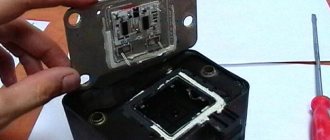
Opening the ignition module
Repair of the ignition module is carried out in the following order:
- On the removed device, open the case by prying it off with a screwdriver.
- Remove the silicone film covering the board.
- All aluminum is removed from the explosive contacts.
- On the board, new wires are soldered in place of all the dismantled old ones. To do this, the surface of the collector is cleaned of deposits, after which the board is heated to 180 o C (a characteristic smell will indicate when the desired temperature has been reached). During the soldering process, the ends of the wires are connected to the module.
- At the end of the operation, all contacts, the board and the module are covered with nail polish.
- The device is assembled in the reverse order, installed on the car and the engine is started. In case of normal operation, the ignition module is sealed tightly with sealant, while the wires are tucked inside the cavity so that they are not pinched at the edges by the plate.
If the device does not work, then a breakdown inside the module should be looked for more carefully. The transistor, electronic component may have failed, or there may be a break in the coil. Such a repair makes sense only if its price is significantly lower than the cost of a new part.
Version of the module on the 8-valve VAZ-2112
Two 8-valve engines of different volumes were installed on the twelve-wheeler - 1.5 and 1.6 liters. The ignition modules for these engines are different. The one and a half liter engine has a module with article number 2112-3705010, and the 1600 cc engine is equipped with a module 2111-3705010. A module for a 1.5 liter engine costs about 1500-2100, and the second one is 500 rubles cheaper.
Module structure
It consists of two ignition coils and two high-voltage switch switches. The coils are designed to create high-voltage pulses.
In essence, it is a simple transformer that has two windings: a primary winding, with an induction voltage of approximately five hundred Volts, and a secondary winding, with an inductive voltage of at least twenty kiloVolts. Everything is placed in one housing with one connector for signal wires and four for high-voltage.
Structure of the ignition coil module of the VAZ 2112
The operation of the ignition module is based on the “idle spark principle”. The module is capable of distributing a spark in pairs: to the first and fourth, second and third cylinders when transmitting pulses from the electronic control unit.
Ignition module for injection engine of VAZ 2108, 2109, 21099 cars
The ignition module on the injection engine of VAZ 2108, 2109, 21099 cars is part of the ignition system.
Purpose of the ignition module
The ignition module on VAZ 2108, 2109, 21099 cars is designed to create high-voltage voltage on the spark plugs at a certain moment.
Location by car
On the 2111 engine of VAZ 2108, 2109, 21099 cars, the ignition module is installed on a special bracket mounted on the front of the cylinder block on the gearbox side.
Ignition module design
The ignition module consists of a housing, inside of which there are two two-terminal ignition coils and a two-channel switch (two electronic units). The housing has four ignition coil terminals, which are connected to the spark plugs in a certain order. The wires for the first and fourth cylinders are connected to the two terminals of one winding, and the wires for the second and third cylinders are connected to the two terminals of the other winding. Therefore, a spark jumps in two cylinders at once (on the compression stroke - working and on the exhaust stroke - idle).
The current supply and control wires from the control unit are connected to the module through a connecting block.
Operating principle of the ignition module
The control unit of the ECM system receives a signal from the crankshaft position sensor about the position of the engine crankshaft and its rotation speed, from temperature sensors and mass air flow sensors information about the condition of the engine and the load on it. After processing the signals, it calculates the ignition timing and sends a command to the ignition module to fire the first or second pair of coils. The ignition module generates high-voltage pulses and supplies them through high-voltage wires to the spark plugs of either 1-4 or 2-3 engine cylinders.
Ignition module malfunctions
A faulty ignition module leads to difficulty starting a cold engine, jerking and failures during acceleration, especially on a cold engine (jerks may disappear after warming up the engine, and with it the ignition module), unstable engine idling (especially when warmed up), increased consumption fuel. Missing sparks lead to the release of a rich mixture into the converter, which leads to its failure.
If you suspect a malfunction of the ignition module, you should first check the high-voltage wires, spark plugs, and electrical circuit of the module.
How to diagnose the ignition coil on a VAZ-2114
As already mentioned, when the first signs of malfunctions appear in the VAZ-2114 ignition module, the vehicle owner should diagnose it. You can perform a similar procedure yourself at home using the following algorithm:
- Check the spark plugs.
- Check the crankshaft position sensor.
- Check the ignition coil.
At home, all stages of the checks can be performed independently. The first stage is checking the spark plugs. It is carried out in the following sequence:
- We remove the spark plugs from their sockets - remove the tips of the high-voltage wires (a special spark plug wrench is suitable for this).
- We examine the candles.
- We clean them from possible soot.
- We set the correct distance between the electrodes.
- We check the spark plugs for operation using improvised means (for example, from a device made from a piezo lighter) or on a car engine with a working ignition system.
If the spark plugs are in good condition, you can proceed to the next stage of checking for faults in the ignition module.
The second step is to check the crankshaft sensor. This test is carried out using a multimeter, thanks to which two characteristics are checked - voltage and resistance. To do this proceed as follows:
- Remove the crankshaft sensor.
- Measure resistance:
- a special ohmmeter mode is installed on the device;
- the terminals of the device are connected to the ends of the winding, which is brought to the surface;
- with optimal sensor operation, digital readings will range from 500 Ohms to 700 Ohms.
- Measure voltage:
- switch the device to the mode for measuring alternating voltage;
- terminals are connected to the ends of the winding;
- any handy object made of metal should be passed along the body of the crankshaft sensor;
- When the sensor operates optimally, the device will show increased voltage readings because there will be a metal object nearby.
Otherwise, the faulty sensor will have to be replaced with a new one, because it also affects the operation of the VAZ-2114 ignition module. If after this there are still signs of coil malfunction, then you should proceed to the third stage of the test.
The third stage is checking the ignition coil itself. This part is checked as follows:
- The easiest way is to replace the coil with a new one;
- while the car engine is running, you can move the coil and knock on it (if there are visible changes in the functioning, it is time to judge a faulty contact in the coil itself);
- take measurements with a multimeter for resistance readings, such indicators are taken from paired coils - they should be identical, approximately equal to 5.4 kOhm.
What to do if you don’t have a multimeter, but you need to check the electrical circuit? Experts recommend using a twelve-volt light bulb. To do this, one of the wires coming from it should be connected to the terminal, and the second wire should be shorted to the motor housing. If the control light flickers when the starter starts, then everything is in working order.
If the car owner has problems performing such diagnostics himself, he can always turn to qualified specialists at a service station.
Recent comments
- Mechanik on Carburetor starting device 2108, 21081, 21083 Solex Check the fuel level in the carburetor float chamber. Plus check if the fuel pump is pumping.
- Boris on Carburetor starter 2108, 21081, 21083 Solex After gas does not work on gasoline. The engine starts for 2-3 seconds and stalls. Half a minute later the same thing.
- Boris on Carburetor starter 2108, 21081, 21083 Solex engine starts but stalls after 2-3 seconds. after 0.5 minutes the same thing
- Andrey on Replacing thresholds on a VAZ 2108 Thank you, useful article. I also have to change the threshold on the eighth road.
Causes of ignition coil failure
Let's look at the reasons why the ignition coil fails.
Natural wear and tear
Like all electrical and electronic units, the reel has a certain trouble-free operation life. The average service life of ignition coils is approximately seven to ten years of operation or 150,000 - 200,000 thousand mileage. The device is operated in extreme conditions with large differences in temperature, humidity, and the possibility of ingress of moisture, dirt, and foreign liquids. In this case, large currents flow through the primary winding, and a high-voltage pulse is formed in the secondary winding.
Electrical breakdown
Let's figure out why the ignition coil breaks. Firstly, over time, as a result of high temperature changes, the dielectric insulation cracks, and salty moisture, which is a conductor, can enter microcracks. For voltages of more than 15,000 volts generated in the secondary winding, even pure undistilled water acts as a conductor. Secondly, during operation, the physical properties of the dielectric and rubber insulation of the tips of high-voltage wires, especially those of dubious production, change. High-voltage breakdown can be caused by the installation of non-standard high-voltage wires in which there is no distributed current-limiting resistance. A breakdown can occur as a result of severe contamination or waterlogging. Even in the event of a single breakdown, irreversible changes occur in the structure; further operation is not recommended.
How to check the ignition module?
We have already learned what the ignition module is and what are the signs of its malfunction (unstable idling, failures during acceleration, engine twinkling).
In this article we will talk about how to check the ignition module with your own hands.
From personal experience: on the Internet, while reading various forums on this topic, I came across a post that broken high-voltage wires do not affect the ignition module in any way. In fact, faulty high-voltage wires can lead to the fact that a spark, in search of the shortest direction, can be sent to a nearby relay, which contributes to module burnout.
Let's move on directly to checking the ignition module. To correctly and accurately check the ignition module, you need a device such as an oscilloscope. But, as a rule, the average driver does not have anything like this, except for the usual warning light and tester, so our task is to use only these devices that are available to everyone.
Checking the ignition module
Before checking the module itself, we need to check the block of wires coming to it. To do this, first of all, disconnect the wiring block, take the tester and connect one tester probe to the block at pin A, connect the other probe to engine ground. Turn on the ignition and look at the tester readings: the voltage should be around 12V. If there is no voltage, then you need to check the fuse. going to the ignition module. The next step is to take a 12V control lamp and connect it to contacts A and B. Turn on the starter and look: the lamp should blink, if it does not blink, then there is an open circuit on contact A. We perform this operation similarly with contact B.
There are several ways to check the ignition module, and we will look at some of them.
1. The first and easiest way to check a module is to replace the module with a known working one. Everything is simple here: we take the module from the donor’s car and change it. But there are certain disadvantages:
- The donor car may not be available, buying a new module does not suit our task;
- Not every car will have an ignition module: “of course!” - you say, - “from SAMAR this will do.” But not everything is so simple: as a rule, the first Samaras with a 1.5 liter engine are equipped with an ignition module. New Samaras with 1.5 and 1.6 liter engines are often equipped with ignition coils. Let me remind you that the ignition module consists of a switch and an ignition coil. In new Samaras the switch is located in the ECU. Therefore, the module is eliminated as unnecessary, leaving only the coil. Take this fact into account and look for a new donor;
- It is imperative to make sure that the high-voltage wires are in good condition: how to check the high-voltage wires?
Otherwise, there is a high probability that the ignition module will burn out.
2. The next method is the method of moving the module. To do this, we move the block of wires, knock and move the module itself. If, at the moment of our influence on the module, the operation of the engine changes noticeably, then the matter is most likely in poor contact. This malfunction is not catastrophic, so you can try to repair the module yourself: Repairing the ignition module. If the module cannot be repaired, then it must be replaced (Replacing the ignition module).
3. To check we need a tester. Using a tester in ohmmeter mode, we measure the resistance at the paired high-voltage terminals of the ignition module 1 and 4 of the cylinder; and between cylinders 2 and 3. The resistance should be the same but vary around 5.4 kOhm.
Video “Visual guide to replacing MH”
The STO TONN channel presented a visual aid for replacing the ignition module on a domestic VAZ 2114 car.
Due to a malfunction of the ignition module, the following malfunctions may occur in the operation of the injection engine of VAZ 2108, 2109, 21099 cars: the engine “triples”, “doubles” (works or tries to start on two cylinders), unstable idling, “dips”, “jerks” , “twitching”, etc.
— Multimeter, autotester or other device with ohmmeter and voltmeter modes
— Socket wrenches or heads for “13” and “17”
Preparatory work
— Remove the ignition module from the engine
Disconnect the ends of the high-voltage wires. Use a key set to “13” to unscrew the two upper fastening bolts, and use a key set to “17” to loosen the tightening of the bottom bolt. Remove the module along with its bracket.
The procedure for checking the ignition module (coil) of the ignition system of VAZ 2108, 2109, 21099 cars with an injection engine
In garage conditions, you can check the secondary windings of the ignition module for an open circuit and the primary windings for a short circuit, as well as the voltage supply to the module from the ECU. This is quite enough to diagnose the problem.
— Check for short circuit
The positive probe of the multimeter in ohmmeter mode to terminal “D” of the ignition module connecting block, the negative probe to the bracket (“ground”). If there is no short circuit, the device readings tend to infinity.
Design of the ignition module VAZ 2109 injector
The design of the ignition module on the VAZ 2109
One of the most complex electrical devices in a VAZ 2109 car on the injector system is undoubtedly the ignition module. This element is found in injection cars; for carburetor cars, an ordinary coil is installed. In fact, the ignition module performs only one, but very important function - it generates a high voltage current, up to 30 thousand watts. Next, the current is directed through high-voltage wires to the spark plugs, and they produce sparks that ignite the fuel in the cylinder block.
Methods for preventing the ignition module on a VAZ-2114
Malfunctions of automobile ignition coils on the VAZ-2114 can be avoided if preventive procedures are regularly carried out. These include:
- Periodic unraveling of high-voltage wires (associated with greatly increased internal resistance, as this can damage the module).
- Checking the spark gap between the electrodes of the spark plugs (if the distance between the electrodes changes, this will affect the efficient operation of the ignition coils).
If faulty spark plugs are identified, they are replaced, after which the car will function properly again.
Design features
It is possible to understand how the ignition module works only using the example of the entire system. So, it includes the following components:
- Ignition coil in a VAZ 2109 car injector. There are always two coils and this is the very mechanism that generates the current.
- High-voltage key switches, there are also two of them, through them the current goes to the spark plugs, in addition, the controller regulates how long the current will be turned on, it calculates the required time based on the data received from the crankshaft sensor.
- Electronic control unit.
- The body of the device itself is made of durable plastic.
In addition, the following elements can be distinguished in the electronic ignition system:
- Crankshaft position sensor.
- High voltage wires.
- Pulley with ring gear.
- Controller.
- Spark plugs that produce sparks.
We will not dwell on these components in more detail and will discuss the principle of operation of the ignition module itself.
Module location
Those who are not very familiar with the structure of the car should know that the device is located in the engine compartment of the car. It's very easy to find. First of all, find the high-voltage wires. One end of them approaches the spark plugs, and the other comes directly from the desired device. The device itself is not very large and is enclosed in a plastic case.
Ignition module for VAZ 2109
labavto.com
One of the reasons for problems with a spark in the internal combustion engine on a VAZ 2109 is a malfunction of the ignition coil (IC). To accurately diagnose a malfunction, you need to know the design of the unit, be able to check it and, if necessary, install a new product.
Coil design features
This unit is designed to convert low on-board voltage (12 V) into high voltage (15-30 thousand V), which is supplied to the spark plugs to ignite the fuel assemblies in the engine cylinders. The impulse is transmitted through high voltage wires.
Both engines with injector and carburetor engines have an ignition system with a distributor (distributor). The scheme of work is not complicated. The distributor receives low-voltage current, which is then transmitted to the short circuit. The received pulse is converted into high-voltage current. Then the distributor distributes it in a certain order to the candles.
The main elements of the coil are the primary and secondary windings, wound on an external magnetic circuit. The first one has a small number of turns of copper wire - from 100 to 150, but it has a large cross-section. The second has a much larger number of turns - from 15,000 to 30,000, the wires are also made of copper, but with a smaller cross-section. There is a primary winding on top, and a secondary winding inside it.
Main malfunctions of the ignition module
Perhaps the main indicator of a malfunction is when there is no spark at the spark plugs. However, there are other signs of unstable module operation:
- No dynamics when accelerating. You can feel obvious dips at the moment of a sharp increase in speed.
- The car does not have the usual power; it even happens that the car simply does not pull uphill.
- Floating idle.
- One of the pairs of cylinders is not working. In this case, most likely there is no current from the ignition coils.
If you encounter similar problems, you should check the spark plugs that do not have a spark, the crankshaft position sensor and the ignition module itself.
Checking the system for functionality
So, it’s best to start with candles that have no spark. This is done in an elementary way and even a person very far from car repair can cope with such a task. For greater clarity, let's divide the whole process into stages:
- The first thing you need to do is unscrew the spark plugs. This is done quite simply. Remove the high-voltage wires and then simply unscrew the spark plugs with a special wrench.
- Now that the spark plugs from which there is no spark have been removed, carefully inspect them. Spare parts should not have carbon deposits or mechanical damage.
- Throw away damaged candles and put new ones in their place; most likely, this will solve the problem. If everything is in order, then there is no spark for another reason.
Next, before proceeding directly to diagnosing the ignition module itself, you should check the block of high-voltage wires that fit to it. Perhaps there is no spark due to their fault. This is done using a special tester. The voltage on the wires during testing should be around 12 volts.
If everything is in order with the wires, most likely there is no spark precisely because the ignition module is faulty. There are many options for checking the functionality of this device. Let us examine in detail the most important of them:
- The most basic one is that you can simply replace the module with one that is known to be functional. Is it true. The problem is that often there is simply nowhere to get an additional module, and buying a new device just to test it is not very smart.
- Another not very difficult way to check is by moving the module. This is done as follows: while the engine is running, move and knock on the device. If the engine's performance changes in any way at this point, most likely the problem is that the necessary contact is missing. In fact, the malfunction is not catastrophic and in this case everything is fixable. At least there is no need to spend money on a new module.
- This option is the most accurate and requires a tester. We put the tester in ohmmeter mode, after which we measure the resistance on the wires, the same high-voltage ones that conduct current. It is necessary to concentrate specifically on the terminals of the ignition module between cylinders 2 and 3 and between the first and second. If the module is working properly, the value should be identical, around 5.4 kOhm.
Preventing ignition module malfunctions
Despite the fact that the ignition module is a very reliable device, cases when it fails still occur.
However, if you use a few simple tips, the device will work much longer:
- Always ensure that high-voltage wires are in the correct order. If they have a resistance higher or lower than required, the ignition coils may fail.
- Timely replacement of spark plugs is also very important. A large gap on these spare parts has a very negative effect on the operation of the module.
High voltage wires
Often, the main difficulty when repairing a carburetor VAZ 2109 is the reconnection of high-voltage wires that were previously disconnected from the distributor cover. It's also an ignition distributor.
The difficulty is that many people forget the connection procedure or simply do not know. But in practice, returning high-voltage wires is much easier than understanding the ignition module used on the injection VAZ 2109.
By following a few simple rules, you can easily return the wires to their rightful places.
- The ignition distributor cover is installed in its place, that is, on the distributor, only in a single position. Therefore, even if you wanted to, you won’t be able to confuse anything here. Otherwise the lid simply won't fit.
- There is an installation mark on the cover, which indicates the location of the wire socket from the first cylinder.
- The wires must be connected in the following sequence - 1, 3, 4, 2. Move counterclockwise when looking at the distributor cover from the side of the expansion tank.
If for some reason there are no installation marks on the VAZ 2109 carburetor distributor cover, just follow the connection principle shown in the image.