The car jerks, there is no traction, vibration is felt, or the engine is rough; all these are symptoms of improper operation of the individual ignition coil (IIC). Other signs of a faulty ignition coil are the presence of errors 0301, 0302, 0303 and 0304, indicating misfire in one of the cylinders. Let's look at a few simple ways to check the ignition coil with your own hands.
It is worth noting that the process of checking IKZ on modern Lada cars (XRAY, Vesta, Largus, Granta, Kalina and Priora) does not have significant differences. All actions are performed in the same way.
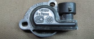
Visual inspection of the IKZ
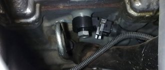
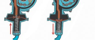
Remove the ignition coils from the engine using a 10mm or Torx E8 socket wrench (depending on the powertrain model). Carefully inspect the removed coils. There should be no cracks, damage to the rubber cap, melting or leakage of plastic. The spring located inside the coil must be in the correct position.
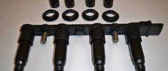
Tip repair
A cracked ignition coil tip is a common problem.
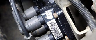
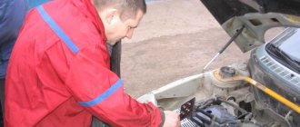
However, you can return the coil to working condition by making repairs on your own, provided that the coil itself has not burned out. This will require a degreasing wipe, a silicone ignition coil O-ring (new), a new tip and silicone sealant. The whole procedure will take a couple of minutes. With numerous and sometimes even minor misfires, the engine may operate unstably, floating speeds will appear, the car may jerk while driving, etc. To determine which cylinder is faulty, it is necessary to alternately remove the coil power plug from each of them, or rather, disconnect it for a while.
If, if one of the cylinders is disconnected, interruptions in operation are still present, then this is where the reason lies. Often, it is the ignition coil of one of the cylinders that leads to the consequences described above. And to replace it, you will need the following tool:
- 10 mm head
- Extension
- Ratchet or small wrench
Checking the ignition coil with a multimeter
Checking the voltage at the terminal block of the wires:
- Disconnect the block with wires from the ignition coil (on the H4M engine, to access the coils of cylinders 1 and 2, remove the intake pipe).
- Turn on the ignition and measure the voltage at terminal 3 of the wiring harness block (the numbering of the terminals is on the ignition coil).
- The voltage at the terminal must be at least 12 V. If it is less or absent, it means the battery is discharged, there is a fault in the power circuit, or the engine control unit (ECU) is faulty.
- Turn off the ignition.
How to check ignition coil resistance:
- We set the switch on the multimeter to the 200 Ohm position and close the probes (the instrument error will be displayed on the screen, which will need to be subtracted from the readings during testing).
- We check the primary winding of the ignition coil by connecting the probes of the device to the contacts.
- The resistance between pins 1 and 3 should be close to zero (about 1 ohm).
- The resistance between pins 1-2 and 2-3 should be high (tend to infinity).
- Set the switch on the multimeter to the 2000 kOhm (or 2 MOhm) position.
- We check the secondary winding of the coil by connecting the red probe to the spring inside the rubber cap, and the black probe to pin 2.
- For good contact, it is best to remove the rubber cap from the coil and connect the probe directly to the coil contact, having first cleaned it of deposits.
- The resistance should be about 300-400 kOhm.
Attention! The resistance of the secondary winding of the ignition coil is highly dependent on its temperature. Carry out the test when the coil is completely cool. Compare the resistance of all four ignition coils to each other. A faulty ignition coil can be identified by very different values, provided that all coils are from the same manufacturer.
The process is also shown in the video:
Checking the ignition coil yourself. Video instruction ZR:
Rear license plate light pinout
According to traffic regulations, the state license plate illumination must always be in working order. For lighting, W5W incandescent lamps are connected, each with a power of 5 W.
The small wiring harness for the rear license plate light (harness serial number 2170-3724214) consists of wires with cream ends and is located in the luggage compartment. The operation of the entire lighting system depends on its quality. The harness responsible for the rear license plate illumination has 3 terminals:
| № | Decoding |
| 1 | Supplying voltage to the lights illuminating the rear number |
| 2,3 | License plate lamps |
| 4 | Electric tailgate lock motor |
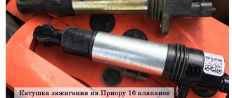
Ignition coils in the electronic circuit of Lada Priora
The ignition system on Priora differs from the usual classic scheme of carburetor models. On old cars there was one ignition coil, and the specific distribution of impulses to the spark plugs was carried out by a distributor, which still needed to be configured correctly. On injection models of cars with electric fuel injection, each cylinder has a personal > newspaper, a personal ignition coil, which supplies an impulse to the spark plug for its own cylinder.
The entire process is controlled by the ECU, an electrical on-board device, from which the signal goes directly to the short circuit. If you set a goal to correctly control the injection process and send a signal to an electronic impulse at the right time, the ECU uses data from the following sensors:
- DPK - taking into account the position of the engine crankshaft, it sends an impulse to the ECU;
- phase sensor - it talks about the position of the camshaft, masters call it a synchronization sensor;
- tachometer - from it a signal is sent to the ECU at what frequency the crankshaft rotates;
- Mass air flow sensor - through the use of measuring air flow through the air filter, determines the load on the engine at this point in time;
- DTOZH - determines the engine temperature;
- DT is a knock sensor, its readings affect the ignition timing.
Under standard criteria, according to the ECU signal, the cylinders operate in the subsequent cycle - 1 - 3 - 4 - 2.4.
In other words, the impulse to the spark arrives in those cylinders in which the compression cycle is completed, before the valve opens, fuel is injected and a discharge occurs, detonation occurs and the cycle continues.
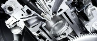
Ignition of gasoline in the cylinders of an internal combustion engine occurs using a spark generated by the ignition system. The ignition module is the main element of the system, creating a spark on the spark plugs using high voltage. Each car manufacturer develops and produces its own original module, but the principle of its operation is the same for all devices. During operation, deviation from the specified parameters or breakdown of the ignition module negatively affects engine operation until the power unit fails.
Pinout of the lighting control unit on Priora
This switching and control combined module has several functions and is used to turn on/off parking lights, headlights, select the desired light switching mode, turn on/off fog lights, adjust the brightness of the backlight combination, control the headlight range control, on/off and control light inside the cabin and instrument lighting. The module is connected to the vehicle’s on-board network via chip No. 1118-3724500.
The standard terminal pinout on a VAZ 2170 is as follows:
| G, 56b | To the gear motor for adjusting headlights |
| 58b | Output to backlight sources |
| 31 | Weight |
| Xz | +12 volts (from terminal 15 of the ignition switch) |
| 56 | To the relay for switching high and low headlights |
| 1,3 | From rear and front fog lights |
| 2,4 | To the rear and front fog lamp relays |
| 58 | To the size lamps |
| 30 | +12 V from terminal No. 30 of the ignition switch |
Purpose and principle of operation
Ignition module VAZ 2110
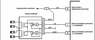
The ignition module of a modern car performs the function of generating high voltage to produce a spark at the spark plugs. It consists of two coils with a closed magnetic circuit and a two-channel switch. Sometimes the switch is made as a separate device, but in most cases it is combined with an electronic control unit for the engine. Externally, the modules differ in the number of wires in the connection connector: a module with a switch has 4 wires, and paired coils have 3.
The ignition module is controlled by the ECU, which supplies constant voltage in the form of low-voltage control signals to the windings of its coils at the right moment. The end of the signal is the beginning of the spark. Thanks to magnetic induction, at the moment of application, a high voltage is generated, creating a spark at the spark plug. The device is located in the engine compartment and can be easily identified by the high-voltage wires leading to the spark plugs.
Pinout for left front door
Most modern vehicles are equipped with a variety of driver comfort systems, one of which is the driver's door module.
The function of the button block located on the driver's door is to control the front windows and exterior mirrors, as well as the automatic locking of the car doors. The installed auxiliary left rear wiring harness (part number 21703-724551-90) comes complete with contact carriers made of electrically conductive materials.
| Contact no. | Decoding |
| 1 | Connector for the additional rear left harness to the rear harness |
| 2 | Rear left harness connector to front left speaker |
| 3 | Electric window lift |
| 4 | Armrest control module |
| 5 | Electric drive for locking the left front door |
| 6 | Left outer rear view mirror control chip |
Signs of a malfunctioning ignition module
A malfunction of the ignition module is determined by the following symptoms:
- Difficulty starting a cold engine due to lack of spark on one or more spark plugs.
- Floating engine speed at idle is a situation in which the speed changes without any action on the part of the driver.
- Dips in power, which manifests itself during acceleration and driving up a long climb.
- Decrease in engine power.
- Cylinders 1-4 or 2-3 do not work (engine “troits”).
- Indication of the “Check Engine” indicator.
Trouble the engine: why is it dangerous?
This is a rather critical phenomenon, especially if the unit begins to vibrate during acceleration.
This behavior of the engine is especially dangerous when the driver decides to overtake, but there are cars in the oncoming lane. In the process, while the motor is running, the engine power is significantly reduced. The compression ratio decreases - there may not be enough dynamics to successfully complete the maneuver.
Considering that the Lada Priora has been manufactured since 2007, there are often instances where the engine knocks like on an old car 20 years ago. This is an engine running on three cylinders. It may have the latest firmware, but if the Lada Priora has a bad engine, then such a car will not have much life left.
Possible causes of ignition module malfunction
Despite the high reliability and durability of the ignition module, during operation it can fail, like any other mechanism. Among all possible causes of breakdowns, in 9 out of 10 cases the following occur and are diagnosed:
- Use of inappropriate components in the ignition system. High-voltage wires are selected based on the parameters of the module, since excessively high or low voltage creates malfunctions or burns out contacts.
- Defective or damaged parts, poor quality assembly. Defective components break down faster and damage other components or elements of the system. Practice shows that the selection of high-quality components and their periodic diagnostics allow the module to remain operational for a long time.
Checking the ignition module
Checking the ignition module for functionality is carried out in the following ways:
Replacing the ignition module with a known good one
1. The easiest way is to connect a known working module. In this case, the devices must be completely identical, the high-voltage wires are in good condition, and the reliability of the contacts has been checked.
Checking the contacts on the ignition module
2. Moving the module, which allows you to identify unreliable contacts. To do this, move the wire block and the module itself. If during exposure the engine reacts by changing its operation, then the cause of the problem lies in poor contact.
Rear door harnesses
The electrical wiring for the rear right and left doors is identical, using only two terminals. The rear door wiring harnesses are factory marked 2170-3724550-10.
| 1 | Block for connection to the rear wiring harness |
| 2 | Rear door lock motor |