The ignition module (IM) of the Niva-Chevrolet car is highly reliable and, most often, provides sparking over many tens of thousands of kilometers. However, if it fails, it is difficult to diagnose due to the lack of obvious signs. The decent cost of a module does not always allow it to be replaced with a new one, which is called “blindly”. First you need to reliably verify that the old one is faulty. Read the article about how to check the ignition module of a Niva-Chevrolet.
Briefly about the design
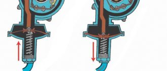
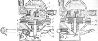
The main purpose of any MZ is to convert a low-voltage signal into a high voltage sufficient for normal sparking in the cylinders. Therefore, structurally, the Niva-Chevrolet ignition module is a pulse transformer. A signal from the electronic control unit (ECU) is supplied to its input, and a voltage of about 20 - 30 kV is removed from the output. The module has a connector for connecting the low-voltage part and four sockets into which the so-called armored wires are inserted.
High voltage is supplied to two cylinders at once. In this case, 90% of the energy is spent on the formation of a spark where the compression stroke ends. The working mixture in it is under high pressure, which means it has high conductivity. Thus, the module consists of two independent ignition coils.
Connecting high voltage wires
The sequence of connecting the high-voltage wires plays a huge role, since the spark in the cylinder is supplied in a certain order, which is indicated by the crankshaft position sensor. As soon as the piston reaches TDC, a spark is supplied to it to ignite the air-fuel mixture.
Below is a diagram of how to connect high-voltage wires on a Niva.
Where is the Ministry of Health located?
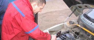
The location of the Niva-Chevrolet ignition module was not chosen very well. It is attached to the bottom of the cylinder block. Thus, the module is exposed to two negative factors at once:
- Corrosion. This is facilitated by the low location. During operation, moisture often gets into the MH.
- High temperature. Mounting the module on the cylinder block forces it to operate at temperatures close to 100 degrees.
The second factor is the most critical for MH. The manufacturer guarantees normal operation of the device up to 120 C°. This kind of temperature under the hood is rare. But constant exposure, even to lower values, significantly reduces the service life of the MH. Therefore, conscientious owners move the module to a place with more benign conditions. Most often, on the partition of the engine compartment.
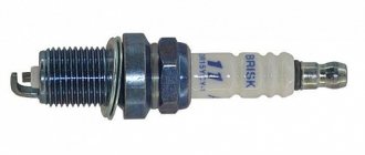
Candle making options:
To increase productivity when creating these products, some technological features are used, which in theory can increase productivity, and as a result, the highest quality fuel combustion:
- Platinum coating. Allows you to increase the service life up to 50 thousand kilometers due to the fact that the surface becomes more resistant to the combustion products of the fuel mixture.
- Multi-contact spark plugs. Typically used in cars that are operated in regions with predominantly low temperatures. Such products make it possible to improve the starting of a cold car in the morning. In summer, it is recommended to replace them with regular ones.
Varieties
During its production, Shniva was equipped with two types of modules.
- MZ from a VAZ 2112 car. Installed until 2006. It includes a spark control system.
- The module is from a VAZ 2111. It is controlled by signals from the ECU, therefore, in essence, it is a regular ignition coil.
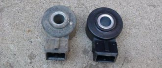
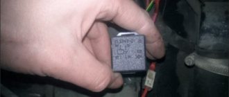
Please note that the modules are not interchangeable. This is due to their different designs. You can determine which ignition module on a Niva-Chevrolet by its appearance. The old one has large dimensions and weight, and most importantly, unlike the new one, there are not three, but four contacts on the primary winding connector. At the same time, the process of checking the Niva-Chevrolet ignition module will be considered using the example of a new module.
How to fix a breakdown
As for the question of how to fix a breakdown, there are two options - fast (“field”) and slow (“garage”). In the latter case, everything is simple - it is advisable to completely change the coil, especially if the breakdown is significant. As for quick repairs, either electrical tape or glue is used for this.
Isolating a damaged coil
The most interesting question for car owners in this context is how to eliminate a breakdown of the injection ignition coil? In the simplest case, that is, if there is a small spark breakdown on the body (and this is the most common type of breakdown), after localizing this place you need to use insulating materials (insulating tape, heat shrink, sealant, epoxy glue or similar means, in some In cases, even nail polish is used, but the polish should only be colorless, without any paints or additives), and isolate the place (path) of the breakdown. It is impossible to give universal advice; it all depends on the specific situation.
When performing repairs, it is necessary to clean and degrease the area of electrical breakdown before applying a protective insulating layer to it. This will increase the resistance value of the resulting insulation. If, when the insulation is damaged and there is a breakdown, liquid appears in the coil (usually from a damaged seal), then it makes sense to additionally use dielectric grease.
Well, in the most severe case, you can, of course, install a new coil. It can be original or not - it depends on the price. Many car owners are saved by the so-called “dismantling shops”, that is, places where you can buy spare parts from disassembled cars. They are cheaper there and you can easily find high-quality components.
Finally, a few words about preventive measures that will allow you to get rid of troubles and operate the reel for a very long time and without problems. The simplest measure in this context is to use heat shrink of a suitable (large) diameter, which must be applied to the surface of the tip of the ignition coil. The procedure is simple, the main thing is to choose heat shrink of the appropriate size and diameter, and also have a hair dryer (preferably a construction hair dryer) or some kind of gas burner on hand. However, before applying heat shrink, do not forget to clean and degrease the working surface of the tip. This procedure can also be used not as a preventive measure, but rather as a repair measure.
Also, for prevention, it is advisable to keep the coil housing, and other engine elements, clean so that there is no “sparking” through dirt and dust. And when replacing spark plugs, always use dielectric grease for spark plugs.
The ignition module (IM) of the Niva-Chevrolet car is highly reliable and, most often, provides sparking over many tens of thousands of kilometers. However, if it fails, it is difficult to diagnose due to the lack of obvious signs. The decent cost of a module does not always allow it to be replaced with a new one, which is called “blindly”. First you need to reliably verify that the old one is faulty. Read the article about how to check the ignition module of a Niva-Chevrolet.
Symptoms of a problem
As already mentioned, symptoms of a faulty ignition module are also typical for many other components of the car. There are almost no signs that directly indicate MH. This significantly complicates repairs. However, with experience, conclusions about a malfunction of the Chevrolet Niva ignition module can be drawn from the following symptoms.
- Two cylinders are not firing at once. This is the only sign that, although not always, indicates MH. The likelihood of this increases if cylinders 1 and 4 or cylinders 2 and 3 are not working at the same time.
- Idle speed “floats”.
- Diagnostics shows misfires in all cylinders.
- As the engine warms up, its power drops and interruptions appear.
- The CHECK ENGIN alarm comes on.
It should be noted that a complete failure of the motor, in which the engine does not start at all, happens very rarely. Basically, this symptom of a malfunction of the Niva-Chevrolet ignition module indicates damage to the low-voltage part of the wiring.
Niva electrical circuit responsible for the equipment built into the front doors
The following is a general breakdown of the electrical equipment of Chevrolet Niva car doors manufactured after 2009. The representation is based on the fact that both sides are almost identical:
- 1/10 – door position limit switches;
- 2/11 – drive of electric window regulator gearboxes;
- 3/12 – plugs for control drives for adjusting the position of rear-view mirrors;
- 4/13 – door lock gearboxes;
- 5/14 – standard terminal blocks for the speaker outputs of the standard acoustic module;
- 6/15 – window switch drives.
Causes of damage
Most often, the Niva-Chevrolet ignition module fails due to overheating caused by its poor location in the engine compartment. This simply leads to a break in the secondary winding of the pulse transformer. However, this can happen for other reasons, namely:
- use of faulty high-voltage wires;
- use of spark plugs other than those recommended by the manufacturer;
- checking the spark by shorting the armored wire to the car body;
- manufacturing defects.
Peculiarities
The operation of the Niva 21213 system depends on the condition of its parts. High-voltage wires must have a distributed resistance, the value of which is in a certain range. Too much resistance will result in the ignition coil not having enough power to cause a breakdown. Low resistance increases interference. Although, some install just such wires. Of course, the spark power will increase and engine performance will improve. Spark plugs can lose their properties over time. The electrodes melt and carbon deposits appear.
The high temperature inside the cylinders greatly heats the spark plugs. Therefore, even when the ignition is turned off, ignition occurs from heated spark plugs.
It is important that all spark plugs have the correct gap between the electrodes. This will ensure high-quality ignition of the mixture. The distributor cap must be clean from dirt, t
because its presence can lead to current leakage
The distributor cover must be clean from dirt, since its presence can lead to current leakage.
Procedure for checking the ignition module
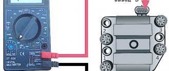
First of all, you will have to get a multimeter. There is no need to look for any high-precision and expensive instruments. The usual Chinese one will suffice. The main thing is that it has a digital display, this will greatly simplify the measurement. The optimal multimeter in terms of price and functionality is the DT 830 and its numerous modifications. This is one of the most common and easy to use devices. The verification process will be discussed using his example.
First of all, you need to make sure that the primary winding of the Niva-Chevrolet ignition module is intact. For this:
- the switch on the front panel of the device is set to the 200 Ohm position;
- disconnect the connector from the module, remove the high voltage wires;
- sequentially measure the resistance between the middle and extreme contacts of the terminal block;
- The device readings should be within 0.5 Ohm.
The accuracy of a multimeter, of course, is not enough to measure such small quantities, but to check the primary winding for an open circuit, this is quite enough.
The next step is to measure the resistance of the secondary. Sequencing:
- set the range switch DT-830 to position 20 K;
- The probes of the device must first be placed between the high-voltage terminals of cylinders 1 and 4, then 2 and 3;
- the device display should display 5.4 kOhm.
It should be said that it is possible to diagnose a malfunction of the Niva-Chevrolet ignition module only if the readings differ significantly from the norm, or, more often, if “1” lights up on the device indicator. This means an infinitely large resistance, in other words, a winding break.
Some gasoline engines that are installed on modern domestic and imported cars are equipped with ignition modules, which are a pulsed high-voltage current source. There are situations when these devices fail, leading to a complete or partial loss of performance of the car engine. Ways to check for a malfunction in the ignition module in a garage are covered in this article.
Description of the camshaft sensor on Niva Chevrolet
Where is it located: in engines with a gasoline power system, the DPRV is installed on the camshaft pulley. In an engine with a diesel power system, the control system is somewhat different. Where the upper and lower position of the piston in each cylinder is fixed.
On engines with a carburetor fuel system, the role of the DPRV is played by the distributor. The design of the injector is different, the system was parallelized, injection and ignition were done in pairs.
During systematic operation, the household equipment wears out and becomes unusable. The process of self-replacement is not at all difficult. The task is feasible for a car enthusiast without technical equipment maintenance skills.
Repeated restart of the engine is the first sign of a malfunction of the DH (DPRV).
To determine which cylinder is on stroke, the electronic engine control unit controls the position of the camshaft using DPRV (SMR)
Data from the sensor is extremely important for setting and dosing fuel, sparks in the combustion chamber, and injectors. The camshaft sensor directly affects fuel consumption, acceleration dynamics, and the amount of emissions in the exhaust gases.
In cars, including Niva Chevrolet, magnetic and Hall effect sensors are preinstalled. Both types are designed to read and transmit data to the electronic engine control unit.
The latter, based on the analysis of indicators, adjusts the fuel supply, ignition timing, and spark frequency.
Signs of DPRV malfunction:
Frequent causes of premature wear of the controller:
Also interesting: Review of standard Niva Chevrolet alarm system Preparatory stage:
The controller replacement is complete. We start the engine and check the serviceability of the equipment.
Design and principle of operation of the ignition module
Some old-school motorists call the modules double-spark coils, which makes sense. After all, the coil is the predecessor of the ignition module in the technical evolutionary chain. The module is a paired design consisting of two pairs of windings (primary and secondary) and a switch that alternately switches low-voltage current from one coil to another. In some models of double-spark coils, the commutator is structurally located outside the block .
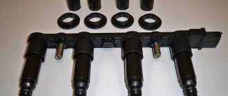
The operation of the module is controlled from an electronic unit that collects and analyzes information from various working components of the engine. The block, unlike the classic coil, has 4 sockets for connecting high voltage wires going to the spark plugs. The pulse occurs in pairs, first at terminals 1 and 4, then 2 and 3. That is, each of the built-in coils is responsible for the operation of two cylinders. A spark occurs simultaneously, as a pair.
This is what one of the ignition module models looks like. The connector for connecting incoming wires is visible at the top.
At the input, the ignition module has a connector with four terminals. Usually most models have markings opposite them. Pulses from the Hall sensor alternately arrive at contacts A and B, serving as a signal to switch the commutator from one primary winding to another. C and D – ground and power supply (12 V), respectively.
Instrument panel pinout
Here is a description of the terminals and terminals of standard instrument panel wiring:
- 1 – diagnostic output, located on the underside of the board under the steering wheel;
- 2 – plug connector for connecting the ECM;
- 3/4 – standard modules for connecting the front connection of the cores responsible for the engine control systems;
- 5/7 – left and right steering column switches;
- 6 – ignition switch device connector;
- 8 – instrument panel combination;
- 9 – output for powering the connector of the contact group of the interior ventilation and heating system;
- 10/11 – lighting plugs for the above equipment;
- 12 – button switch of the alarm device;
- 13 – mounting box for fuse insertion;
- 14/15 – the lamp itself and the button to turn off the lighting of the glove compartment;
- 16 – contact pin for turning off the brake lights;
- 17 – switch of the standard sound warning module (horn);
- 18 – automatic protection of fog lights of head optics;
- 19 – automatic window lifters;
- 20 – protective relay for sound signal;
- 21 – safety module for the seat heating system;
- 22 – starter control relay;
- 23 – switch for the external lighting system;
- 24 – contact group for connecting the stove fan;
- 25 – built-in switch for turning on the heated windshield;
- 26 – device for turning off the front fog lights;
- 27 – switch for stern lights, fog lighting group;
- 28 – air conditioner setting button;
- 29 – position regulator of heating manipulators;
- 30 – cigarette lighter pin;
- 31 – buttons for adjusting the direction of the light flux of the head optics;
- 32 – adjust the brightness of the instrument panel illumination;
- 33 – auxiliary resistor mechanism of the heating fan;
- 34 – standard immobilizer module;
- 35/36 – standard-type onboard acoustic module terminals;
- 37/38 – terminal connectors for connecting the rear harness of the on-board circuit.
Possible causes of failure
The weak point of the ignition coils and modules is the secondary winding, which generates a high voltage pulse. A coil break or breakdown may occur in it. The following factors lead to this phenomenon:
- use of low-quality or unsuitable candles;
- operation with non-functioning high voltage wires;
- frequent attempts to check the spark.
The high-voltage pulse arising in the secondary winding must be realized (spent). If this does not happen (if the integrity of a high voltage wire is broken, for example), a high-energy electrical pulse seeks an outlet. He will find it, with a high degree of probability, in the thin secondary winding.
Often, a module malfunction occurs when the integrity of poor-quality factory soldering of wires going to the switch elements is violated. This happens from vibration. Also, the cause of non-working coils can be a banal contact failure in the incoming connector. Another factor leading to a malfunction of the ignition unit is often moisture that gets on the device during washing or driving in unusual conditions.
Symptoms of a problem
It is extremely rare for two built-in coils to fail at once, so it is more likely to be possible to start the engine with a faulty unit. However, even an inexperienced driver will immediately suspect something is wrong. The malfunction will appear as follows:
- unstable (floating) idle speed;
- the engine has difficulty picking up speed;
- characteristic sound of the engine (triple);
- jerking when accelerating (while moving).
Operating a car with such a breakdown is possible (you can drive to a garage or car service station), but it is not advisable unless absolutely necessary.
Similar signs of unstable engine operation are possible with a number of other ignition or fuel supply faults. To differentiate possible breakdowns, the performance of the ignition unit should be determined. It would be useful to check the contacts of the wires coming to the device, as well as their integrity.
Prevention
To prevent breakdowns, the manufacturer recommends following several tips.
- Once a year, treat all terminals and connectors with special oil - this will prevent the formation of oxides.
- Periodically check the tightness of the contact connectors. If the connections are loosened, short circuits may form or the conductivity of the circuit may decrease, which will be perceived by the ECU as a mechanism failure.
- Check the degree of wear of power cables and lines. During active use of the vehicle, braids made of flexible polymer may wear out and crack. This circumstance can provoke short circuits and mechanical shedding of insulators. Therefore, it is better to prevent a breakdown than to fix it.
If you adhere to the above rules, the car will serve for a long time and with high quality all the time.
Checking module power
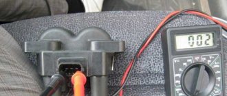
Before testing the performance of the coils, you should make sure that a possible breakdown is not caused by a loss of power to the device . First, you need to try to simply restore contact by moving it several times or disconnecting/connecting the block of wires included in the connector. If such manipulation does not lead to improved engine performance, a tester (multimeter) is used to determine the quality of incoming pulses.
The block of wires is removed from the connector. On the block, each terminal (A, B, C, D) has a corresponding socket. Testing with the engine running is done as follows.
- The first contact of the tester is in socket D, the second is to ground. The multimeter switch position is 20 volts. If there is power, the tester shows 12 volts.
- The first contact is in socket C, the second is ground. Switch on ohmmeter (20 Ohm). Normally it shows less than 1 ohm, that is, the mass is normal.
- The first contact is in socket B, the second is ground. 20 volt switch. The norm is not less than 0.3 volts. If this is so, it means that a normal pulse is coming from the Hall sensor to position B.
- Contact A is checked similarly to the previous one.
If such a check shows the norm, you need to test the module. If not, look for the cause in the electrical circuit to the coil.
Methods for diagnosing device performance
The simplest method that will help determine the performance of the coil is to replace it with a similar working device. This is possible if there is somewhere to get it. Please note that the module must match the parameters of the device under test . If the engine with a working coil works as before the breakdown, the ignition module is definitely faulty.
The main testing method involves using a multimeter. It consists in determining the resistance of the secondary windings of the coils built into the ignition module. The method is simple and does not require additional skills. The device does not need to be removed for testing. The check is done with the engine turned off.
This is how you check the resistance of the secondary winding with a multimeter
- High-voltage wires are removed from the module sockets.
- The tester switch is set to the 20 kOhm position.
- The multimeter rods are placed in turn in the recesses of the corresponding contact pairs (1 and 4, 2 and 3).
- With an intact secondary winding, the performance in both cases is the same. Normally, the resistance should be about 5.4 kOhm (in some models the indicators differ, which needs to be clarified). If the resistance is much greater, then there is a winding break. The resistance is much lower - a breakdown. The coil is faulty and cannot be repaired.
Fines for crossing the stop line and speeding will no longer bother you!
Video: How to check the secondary winding with a multimeter
Niva electrical circuit responsible for the equipment built into the cargo compartment door
- 1 – output of the contact group of the rear bundle of highways;
- 2 – door position limit switch;
- 3 – central locking gearbox;
- 4 – voltage for the rear windshield washer motor;
- 5 – plug for additional brake sign;
- 6 – heated aft windshield;
- 7 – stern glass wiper controller;
- 8 – relay of the above element.
Main types of faults.
Often the cause of problems with the Niva Chevrolet ignition module are breaks in the second winding, because it is this that generates the high voltage pulse. This mainly happens due to the fault of car owners:
- in case of untimely replacement of failed high-voltage wires
- installing spark plugs that do not match the car model.
- moisture ingress due to improper washing
Also, the cause of burnout may be delamination of the solder due to increased vibration during frequent use of the engine at high speeds or during frequent temperature exposure - engine overheating.
Also, if the integrity of the winding of high-voltage wires is violated, extinguishing occurs due to the secondary winding. The charge finds the nearest exit point and enters the place where the wires are thinnest, leading to their destruction.
Problems with the ignition module can be determined in advance, since two coils do not fail at the same time, so car owners will still have the engine start, but with some difficulties:
- it takes a long time to gain working momentum
- floating idle speed
- excessive engine vibration
- jerking while driving
But these problems may be associated not only with the ignition module, so before replacing it is recommended to check its condition
What to look for when purchasing
The spark plug design is not the only parameter that you should pay attention to when choosing such parts. Two more characteristics are important:
- overall dimensions of the candle;
- heat number.
As for the sizes, everything is simple here: a candle that is too small will simply fall into the candle well, while a large one will not fit into it. To accurately determine which spark plugs are suitable for your car, it is worth studying the recommendations from the car manufacturer. Most often, this information is in the car manual; you can also clarify this issue with the dealer or on the forums of a specific brand and model.
You can also easily find spark plug interchangeability tables
. They contain all the dimensional parameters of the candle, and there are many of them:
- thread size on the spark plug body;
- type of installation of the spark plug in the cylinder head (flat supporting surface or cone-shaped);
- wrench size (16.0 mm hexagon size, 19 mm, etc.);
- thread length on the spark plug body.
In order not to remember countless numbers and designations, it is enough to find the very interchangeability table or configurator, where you just need to enter the car make/model/engine type, and you will immediately be offered all the suitable options from all well-known manufacturers.
an important selection criterion, illustrating compression at which uncontrolled ignition occurs. Each brand has its own standards and scales for candle heat ratings. If you ignore this indicator, you can bring the engine to glow ignition
— uncontrolled combustion of fuel, provoked not by a spark, but by contact of the fuel mixture with hot engine parts or carbon deposits.
It is impossible to determine what heat rating is needed for your engine by eye - this is done by the manufacturer at the factory. The candle is marked accordingly. It illustrates the maximum permitted temperature load of the spark plug, its resistance to glow ignition and overheating.
This marking cannot be ignored, since it is almost impossible to determine by ear the line between normal ignition and glow ignition. But if the transition has taken place, the overheated pistons are destroyed in a matter of minutes, and the engine is sent for repair. Too low a temperature also has negative consequences on the engine - in this case, carbon deposits increase and engine power decreases.
Check procedure
First you need to check all the contacts, both those suitable for the block and the high-voltage wires going to the spark plugs. To do this, simply disconnect the wires several times and reconnect them. If this does not bring positive results, you need to move on to the next steps.
To do this, they usually use a multimeter connected to contacts D and the second one connected to ground. The device itself is switched to 20 volt mode. In this case, the readings on it should be 12 volts. Then, using the same scheme, check contact C in ohmmeter mode. The reading should be less than 1 ohm.
Contacts A and B are checked in voltmeter mode. Their readings should not exceed 0.3 Volts. If at least one of these indicators is outside the normal range, you need to look for problems in the coil.
If you find damage to the soldering of the contacts, you can try to fix them yourself using a soldering iron. If the coil is damaged, the ignition module must be replaced.