The situation is as follows: for no apparent reason the engine began to “trouble”, the thrust was lost, and the idle now does not even reach 500. I removed the high-voltage wires one by one, and so, there was no spark at all in cylinders 2 and 3. The engine is 16-valve, but without “individual coils”. The question is how to check the ignition module on a VAZ-2112 engine, and it is advisable not to remove it. Inside the module, in addition to the coils, electronics are installed. How can I check if it's working properly?
Design Features
If you are familiar with the designs of automotive systems, you can draw parallels between the high-voltage coil and the VAZ-2110 ignition module. The malfunctions of this device manifest themselves in exactly the same way. Essentially, this is a symbiosis of a high-voltage coil and a switch. The design includes the following:
1. To generate the high-voltage pulses necessary to ignite the combustible mixture using spark plugs, two coils are used.
2. Two-channel switch made of conductor elements.
The device may fail unexpectedly. Even though your vehicle has a self-diagnosis system, the Check Engine light on your dashboard will not illuminate. Usually one of the commutator channels fails, this is manifested by unstable operation of the motor, sometimes stopping it.
Typical module failures
If you have at least a little knowledge of electronics, as well as a multimeter, you can independently diagnose and identify the problem. Checking the VAZ-2110 ignition module will take a little time, but it will save you from purchasing an expensive unit. Please note that sometimes races appear and disappear over time.
Errors will remain in the microcontroller, so they can be read using special testers. But as practice shows, at a time when the faults do not manifest themselves, the tester cannot recognize error codes that were previously present but then disappeared. Very often, the cause of failures is dirt on the contacts, poor fastening of the case, lack of mass, and the presence of electrical interference.
Removing the ignition module
To repair the VAZ-2110 ignition module, it must be dismantled. First, check if there is high voltage on all terminals. The most common breakdown is the lack of spark in the second and third cylinders. If you lightly press down on the rear of the housing, the engine can begin to operate normally. But it won't last long. To withdraw you need:
1. Disconnect ground from the battery.
2. Remove the decorative cover covering the block head, if any.
3. Remove all high-voltage wires.
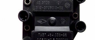
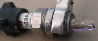
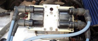
4. Disconnect all wires going to the ignition module. The white rings indicate the numbering of all wires. On the body of the device there is a designation of cylinder numbers.
5. Disconnect the connector from the device.
6. Unscrew the three nuts securing the block.
That's all, the VAZ-2110 ignition module has been removed, and you can start repairing it.
Cost and article
The table below shows the cost of the VAZ 2110 ignition module depending on the manufacturer and VAZ engine size.
| Engine volume | Number of valves | Manufacturer | vendor code | Price, (rubles) |
| 1,6 | 8 | JSC SOATE | 2111-3705010-03 | 905 |
| 1,5 | 8 | BOSCH | F000ZS0211 | 2600 |
| 1,5 | 16 | StarVolt | 2112-3705010 | 1600 |
| 1,5 | 16 | Omega | 2112-3705010 | 1590 |
How to restore
Opening the aluminum plate, you will find a small printed circuit board on which the active components are located. It is coated with transparent silicone. It will need to be removed as it will interfere with repairs. Pay attention to the wires that connect the board and connector pins. They are aluminum, and this metal undergoes destruction much faster than copper. All these wires will need to be replaced. Some motorists who repair modules use wires that are used in mice for personal computers. But you need to get used to working with them - they are covered with paint.
In general, the diagram of the entire module is simple, it contains:
1. Two BU931 transistors (you can use the domestic analogue of KT848A, it performs well and is much cheaper).
2. Two SGS-THOMSON switches (model L497D1).
A little about prices
We have already noted which switch and transistor are used when repairing the ignition module of a dozen. The first costs about 3 dollars, and for the second you will have to pay about 6 dollars.
Some craftsmen use a domestic analogue of the transistor - model KT848A . Of course, it costs less. But its problem is its lower quality and larger size, which somewhat complicates the repair process.
What you need to know when working with the module
Before working with the module, you need to purchase aluminum flux. When replacing transistors, please note that it is very difficult to solder wires to the collector terminals, since they are coated with a special material. And it complicates soldering. To make your work easier, carefully open the spray. Try not to overheat the element. Place it on an aluminum plate so that all the heat goes into it. Otherwise, the semiconductor junction will be destroyed and you will ruin an expensive element.
When soldering wires, make sure that their length is as short as possible. All soldering areas must be coated with varnish, even for nails. After repairs, be sure to check the functionality of the VAZ-2110 ignition module. If it functions normally, then it is necessary to treat everything inside with auto sealant. This will ensure maximum tightness of the unit - neither water nor dust can get into it. And such a device will last for many years. But if the problem does not lie in the contacts or power transistors, it is better to abandon the repair idea and purchase a new module - on a VAZ-2110 it costs about 1,500 rubles.
Performs one of the main functions in the ignition system (IS) as a whole. Thanks to this unit, the engine starts optimally, as well as its normal operation in the future. You can learn more about device malfunctions, as well as its replacement, from this material.
Description of the ignition module
Before we talk about testing and replacing the MZ in our VAZ 2111, let's understand the basic information. To begin with, we suggest finding out what the 2111 ignition module is and where it is located.
Purpose and location
As mentioned above, the MZ is one of the main devices in the ignition system. Of course, if you think about it, all the components of the system are very important, since the quality of operation of the power unit as a whole depends on them. But if this unit begins to work intermittently, then at least two cylinders in the engine will stop working, or even all four. This is due to the fact that the module itself consists of two coils, with one of them supplying current to the first and fourth cylinders, and the second to the second and third. Accordingly, if one coil fails, this will lead to two cylinders being inoperative, which will affect the operation of the engine as a whole.
The purpose of this device is that it converts the voltage supplied from the interrupter device into a high-voltage signal. This impulse, accordingly, is supplied to the cylinder spark plugs in a certain order. It is used to ignite the combustible mixture in the engine cylinders, which facilitates its normal starting and operation.
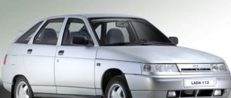
Lada twelfth model
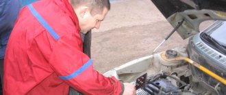
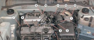
As for the location, it is not difficult to find 2112 16 valves; it is located in the engine compartment. Open the hood and look at the spark plugs - they are connected to them, which come directly from the module itself. The MZ itself is a small black square box, so you won’t be able to confuse it with anything else.
Common faults
Only diagnostics will allow you to accurately determine the malfunction of the module, but there are indirect signs that can inform the car owner about a problem in the operation of the device.
If the MZ malfunctions, an error light appears on the dashboard.
So, in what cases is it necessary to replace or repair the VAZ ignition module:
- Starting the power unit has become more difficult. Now the driver needs to turn the starter more to start the engine.
- Engine idling has become unstable. The engine may rev, and the speed may rise and fall.
- The power of the power unit as a whole has decreased. When you press the gas pedal, the car takes longer to accelerate. This symptom is especially obvious when driving uphill. Also, when pressing the gas pedal, dips may be observed - the driver presses the gas, but there is no effect.
- Fuel consumption has increased. Of course, without a fuel consumption meter, it will be difficult to determine such a malfunction. But if you are used to refueling a certain amount of fuel for a certain mileage, you will also be able to recognize this sign (the author of the video is the Auto_Remont channel).
All these symptoms, as stated above, are indirect, since they can also appear with other malfunctions. For example, if the fuel filter is clogged or its service life has come to an end. Also, such signs appear as a result of wear of the spark plugs or high-voltage wires. Therefore, if you are faced with such a problem, then first of all you should make sure that there is no carbon deposits on them, and also check the armored wires. It happens that one of the wires is simply poorly connected to the spark plug, or it is broken or worn out.
Checking the Ministry of Health with your own hands
There are several options for checking the device yourself at home; let’s look at the simplest one.
To carry out independent diagnostics, you need to know what the wires connected to the module are responsible for:
- red-blue - provides 12-volt power to the device;
- the brown wire is ground, usually connected to the car body;
- white-blue - connects to the spark plugs of the first and fourth cylinders;
- the red-gray wire connects to the spark plugs of the second and third cylinders.
Scheme of the VAZ module
First, you need to check with your own hands that all pulses are sent to the ignition device 2112:
- First of all, you need to turn off the ignition and disconnect the connector.
- Next, the key in the lock must be moved to position I.
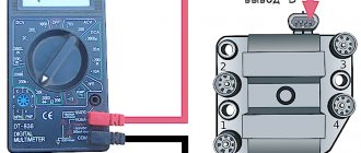
- Now you will need a dial voltmeter; it must be connected to the negative terminal of the battery.
- With the second probe, that is, the plus one, you need to find the 12-volt contact on the connector.
- When connected to the control contact, the arrow on the tester will show almost 0.
- If the starter unit starts working, the parameters may increase, but they will not exceed 0.7 volts. Please note that the voltage level at both control contacts must be identical.
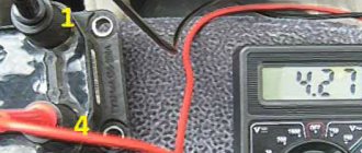
There is another test option - you can diagnose the functionality of the module using a pointer ohmmeter. In this case, we mean a pointer tester, not a digital one. First you need to connect the probes of the device to pins 1 and 4 of the module, and after that to pins 2 and 3. Ultimately, the diagnostics should show the same result.
Please note that depending on the manufacturer, these parameters may differ:
- for devices manufactured by ATE-2 with number 3705010-02, this parameter should be about 5-6 kOhm;
- for SOATE modules with number 3705010-12, diagnostics should show 12 kOhm.
If the obtained indicators differ from those described above, then the module must be replaced. Please note that the inductance of the coils installed inside the MZ is quite high, therefore, connecting an ohmmeter, a spark may slip. Therefore, when diagnosing, we strongly do not recommend touching the probe leads at the same time (the author of the video is Avtoelektika HF).
Symptoms of a problem
Based on some signs, it can be determined that the culprit of a malfunctioning internal combustion engine is the MZ. Below is a small list of symptoms indicating failure of the MH.
Signs:
- Failure of two cylinders at once, namely 1-4 or 2-3;
- Increased fuel consumption;
- Detonation at idle speed;
- The engine does not develop power;
- Difficult starting on a hot internal combustion engine;
These signs indicate a malfunction in the ignition system. These signs also apply to other possible breakdowns: spark plugs, wires and even injectors, but first of all you need to pay attention to the MH.
Instructions for replacing the module
If checking the VAZ 2112 ignition module showed that the device needs to be replaced, then you can change the ignition module yourself.
The replacement process looks like this:
- Initially, you should turn off the power to the on-board network; to do this, you just need to disconnect the negative terminal from the battery. Many car enthusiasts neglect this step, although in fact it is very important. If you do not disconnect the battery, a short circuit may occur as a result of moisture or other external influences during repairs. And if this happens, then there is a chance that you will have to completely change the wiring in the car. So, to reset the battery terminal, you just need to unscrew the bolt that secures it with a wrench.
- Having done this, you will need to disconnect all high-voltage wires connected to it from the module. At the same time, you need to remember their location so that during installation you do not accidentally confuse them, which, again, can be fraught with danger for the entire system as a whole.
- After completing these steps, you will need to disconnect the connector with wires from the device itself. To do this, grab the block with your hand and press the latch with which it is attached - the fastener is located at the bottom, you can feel it with your hand. Having done this, you will need to remove the block and put it aside so that it does not interfere with you in the future.
- So, now you have two options - remove the device together with the mount or remove it separately. The first option is usually relevant in cases where, in addition to replacing the MZ, you need to perform other repair actions, for example, to get to the antifreeze drain hole of their cylinder block. Of course, it will be more convenient to dismantle the module separately, but then access to other parts and elements will be blocked. To dismantle you will need to unscrew the nuts with your own hands that secure the device to the bracket. Depending on the car, the nuts can be different; for example, they can be made in the form of hexagonal studs. If so, you will need a hex wrench to unscrew them. In any case, after unscrewing the nuts, it is necessary to dismantle the module from the seat.
- The procedure for installing a new module is carried out in a similar way, only in reverse order. When connecting with your own hands, be careful and be sure to correctly connect all the wires that connect to the module from the spark plugs. If at this stage you mix up the cylinder numbers on the high-voltage cables, the power unit may not work correctly or may not start at all.
Photo gallery “Replacing the MZ with your own hands”
Price issue
The cost of the device directly depends on the manufacturer. For example, the price for a new MZ from the manufacturer SOATE is about 1,700 rubles. A module from the manufacturer BOSCH will cost around 2 thousand rubles, and from General Motors - about 5 thousand rubles.
Advice.
To quickly check the serviceability of the ignition system, you can use a spark indicator for engines with fuel injection. It is put on the spark plug and a high-voltage wire is connected to it. When checking, you must follow the instructions supplied with the device.
Comment.
The 21114 engine uses an ignition coil. The 2111 engine may have an ignition coil or ignition module installed (see Engine Management System). The ignition coil replacement is shown below. Replacing the module is done in the same way.
To do the job you will need a multimeter.
Execution Sequence
1. Prepare the car for work (see “Preparing the car for maintenance and repair”), turn off the ignition.
2. Having released the latch, disconnect the wiring harness block (1) from the terminals of the ignition coil (module) (2).
3. Turning on the ignition, use a voltmeter to measure the voltage between terminal 15 and ground (for the ignition coil) or between terminals C and D (for the ignition module) of the wiring harness block.
Warning!
After taking measurements, turn off the ignition.
Comment.
The voltage must be at least 12 V. If the voltage is not supplied to the block or it is less than 12 V, it means that the battery is discharged, the power circuit is faulty, or the ECU is faulty.
the ignition module is faulty
possible by replacing it with a known good one.
The ignition coil
can be checked with an ohmmeter.
4. Disconnect the high-voltage wires from the spark plugs (see “High-voltage wires of engines 2111 and 21114 (8V) - check and replacement”).
13 mm socket wrench
unscrew the two bolts of the upper fastening of the ignition coil (module) bracket.
6. With a 17 mm wrench,
Having loosened the lower bolt of the bracket, remove the bracket together with the coil (module).
7. Disconnect the high-voltage wires from the ignition coil (see “High-voltage wires of engines 2111 and 21114 (8V) - check and replacement”).
8. Using an ohmmeter, we measure the electrical resistance between the central terminal 15 and the housing (bracket). The device should show that there is no short circuit of the primary winding of the coil to ground. We sequentially measure the electrical resistance between the central terminal 15 and the outer terminals 1a and 1b. The resistance of each of the primary windings of the coil should be about 0.5 ohms.
Comment.
When measuring small values of electrical resistance (about 1 ohm), it is necessary to take into account the internal resistance of the device, which can be determined by shorting the ohmmeter probes.
9. Using an ohmmeter, measure the resistance between the high-voltage terminals of the coil 1 and 4, and then 2 and 3. The resistance of the windings should be about 5.4 kOhm.
A faulty ignition coil must be replaced.
5mm hex wrench
unscrew the four screws securing the coil to the bracket and remove the coil.
Comment.
10 mm socket wrench
with a deep head, unscrew the 3 screws securing it
11. Install the ignition coil (module) in the reverse order. We connect high-voltage wires in accordance with the cylinder numbers marked on each wire and on the coil (module) body next to the terminals.
Advice.
Since the numbering of the terminals on the coil (module) installed on the engine is not visible, it is better to connect high-voltage wires to the terminals of the ignition coil (module) before installing it on the engine.
Often, when the ignition module breaks down, the car owner immediately runs to the store and buys a new one. But, for the VAZ-2112 there is an alternative method - repair. Of course, without proper knowledge in auto electrics it will be difficult. This article will tell you in the most accessible way how to repair the ignition module with your own hands.
Ignition module
Before you begin repairing the ignition module, it is worth understanding what it consists of.
So, let's look at the design of this element:
- Two ignition coils that generate a high-voltage pulse.
- Dual channel switch.
If there are problems with the operation of the ignition module, there are reasons for this. It is worth warning that in the event of a malfunction, the “Check Engine” warning light will not light up: engine stops, loss of spark, interruptions in the operation of the power unit, etc.
For diagnostics and repairs, basic knowledge is required not only in conventional electrics, but also in the principles of auto electrics. Also, for a successful process you will need skills in working with a digital multimeter.
Repair process
Often, the high-voltage pulse disappears in cylinders 2 and 3
. So, to begin repairing the ignition module, of course, you will need to dismantle it. To do this, disconnect the high-voltage wires and unscrew the assembly itself from the fastenings. When the preparatory operations are completed, you can proceed directly to the repair process:
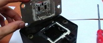
- We tear off the aluminum plate.
Use a screwdriver to open the aluminum plate - The internal world of the ignition module is quite rich and complex, at first glance, but everything is much simpler.
After opening, you can see the printed circuit board in silicone. Remove this sealant. The aluminum wires that connect to the contacts of the connectors and coils are torn. Opening the lid - We disassemble the computer mouse, or rather, only its multi-core wires will be needed.
We also remove all connections from the board. Wire soldering diagram and arrangement of elements on the boards - The ignition module circuit includes two L497D1 switches and two BU931 type transistors, which are considered quite powerful.
We solder everything with a special aluminum flux. Diagram of the assembled ignition module - First you need to solder the wires directly to the board. But soldering the wiring to the transistor collectors is much more difficult, since they are coated with special metal during manufacturing. This material is quite difficult to solder. First, remove the top layer from the metal. Before soldering, so that the heat does not dissipate, you need to place the plate on the stove and heat it to 180 degrees Celsius.
- Now, solder the wires to the contact module. The wire should be as short as possible.
- To insulate the contact soldering area, we coat it with varnish. You can use the one for nails.
- We check the finished product for functionality.
Completely assembled ignition module
Video about repairing the ignition module on a VAZ-2112
The video material will tell you about repairing the ignition module, as well as how to remove it from the car.
Repair
So, for the VAZ 2110 the most common problem is the disappearance of voltage on cylinders 2 and 3. After some time, the engine starts working normally again if you press the rear plate of the module.
You should not put up with such a situation; it is better to immediately check the functionality of the unit, restore or replace it completely.
Removing the module
The procedure is quite simple.
- Disconnect the negative cable from the battery.
- Remove the plastic cover that covers the motor.
- Remove the wires from the spark plugs.
- Disconnect the wires from the ignition module. Their numbering is indicated on special white rings. And the cylinder number is indicated on the ignition module housing.
- Disconnect the connector from the ignition module.
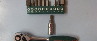
- Using a 10mm socket, unscrew the three nuts that hold the block we are looking for.
- Carefully remove it, after which you can begin further work.
Now let's move directly to working with the module:
- Open the aluminum plate on the ignition module. A flathead screwdriver is useful for this.
- Inside you will find a small printed circuit board with electronic components. It is covered with a transparent layer of silicone, which will have to be removed.
- There are also wires that connect the board to the connector contacts. They are made of aluminum, so they can tear quickly.
- Tear off all the wires from the contacts, don’t be afraid. Others will be installed in their place. By the way, experts recommend using stranded wires used in computer mice.
- The ignition module circuit includes two switches and two powerful transresistors. If you decide to change these elements, you need to know that the switches are manufactured by SGS-THOMSON (model L497D1), and the transistors are of the BU931 type.
- The contacts are made of aluminum, so you will need a special flux to work with this metal.
- We solder the wiring to the board. It is more difficult to solder to the transistor collectors, since they are covered with a special material, the soldering of which is problematic. Therefore, try to hide the top coating from the element as carefully as possible. To prevent the soldering iron from transferring all the heat to the plate, place it on the stove and heat it to 180 degrees Celsius.
- Solder the wires to the contacts on the module so that they are as short as possible.
- Cover the areas where you soldered with varnish. Regular nail polish borrowed from your wife will do.
- Check if the ignition module is working.
- If everything is fine, coat the inner surface with a special autosealant, then reassemble in the reverse order.
- Upon completion of assembly, the wiring should be positioned fairly freely. Make sure that they are not compressed inside the box and that the integrity of the connections is not broken.
Carrying out such a repair of the ignition module on a VAZ 2110 with your own hands will not be difficult. But be careful, act carefully and consistently. Pay special attention to the soldering process.
If the cause of the malfunction lies elsewhere, then there is a high probability that it is better to simply replace the VAZ 2110 8-valve ignition module with a new one. The search may drag on without yielding results. Replacing the element will completely solve the current problem.