Hello, dear pelvic producers! The “Check” signal came on back in July, unexpectedly as always, during a trip to Arkaim.
The Check Engine signal is a harbinger of troubles and unexpected expenses.
The on-board computer interpreted error P0343 as “high signal level of the phase sensor.” Since there was no service station or auto shop expected within a radius of 100 km, I decided to drive with a malfunction. Moreover, the engine started easily and ran smoothly. After 50...60 kilometers the “Check” went out and I was glad that the fault had resolved itself.
However, everything turned out to be completely different. “The check began to light up more and more often, and recently it went out only after resetting the fault code through the BC. But the next time he started, he again began to wink with his red eye. It is typical that I did not notice any changes in engine performance, and fuel consumption, according to the BC readings, even decreased slightly.
It is clear that if the phase sensor fails, instead of distributed injection in each cylinder, a distributed pair is switched on for cylinders 1-4 and 2-3. But, according to theory, the engine should start after about 10 crankshaft revolutions, and fuel consumption should increase. This question tormented me for a long time, but in the end “Check” got to me and I realized that sooner or later the sensor would have to be replaced.
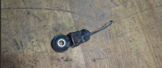
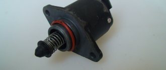
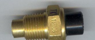
The phase sensor on the engine is secured with a bolt with an x10 head. Replacing it is not difficult. You just need to remember about the rubber sealing ring that may remain in the sensor hole. It needs to be removed, put on the sensor body and lubricated with a drop of engine oil.
In the store, the salesman grinned and asked: “Which sensor do you want, a good one or an ordinary one?” A good sensor cost 430 rubles, and a regular one - 320. I chose a good one.
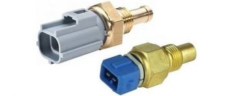
Find 10 differences. New sensor on the right, used. - left
After installing it and resetting the error, the “Check” no longer came on. This is all reasonable and does not contradict common sense. I was confused by the following: while experimenting with the sensor, I removed the connector from it and started the engine, expecting error P0342 “Low level of phase sensor signal.” However, the “Check” did not light up, the engine started at half a turn and worked as if nothing had happened?! So, maybe there was no need to change the sensor? Reset the connector and ride to your health? Maybe someone has encountered such a situation?
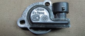
In conclusion, I decided to disassemble the sensor and see what was inside, since I couldn’t find any intelligible information on the Internet (maybe I didn’t look well?). After cutting the case inside, in a loose compound, I found a small signal conditioner board and a Hall sensor consisting of a transistor, a magnet and a tuning screw core.
Inside the case there is a signal conditioner board with two diodes, resistors and capacitors, as well as a Hall sensor with three transistor legs
Actually, the Hall sensor: transistor, magnet and steel trimming core
There are few parts, nothing seems to break. It seems to me that the fault was poor contact between the legs of the transistor and the board tracks, which were simply pressed against each other (if you look closely, traces of contact can be seen in the picture). Now, if they were connected by soldering, the reliability of the unit would be much higher. I hope that this is exactly what makes a “good” sensor different from a regular one.
What is a phase sensor used for?
To understand possible malfunctions of the phase sensor, it makes sense to briefly dwell on the question of what it is, as well as the principle of its design.
Thus, the main function of the phase sensor (or DF for short) is to determine the position of the gas distribution mechanism at a specific point in time. In turn, this is necessary so that the electronic engine control unit (ECU) gives the command to inject fuel at a certain point in time. In particular, the phase sensor determines the position of the first cylinder. The ignition is also synchronized. The phase sensor works in conjunction with the crankshaft position sensor.
Phase sensors are used on engines with distributed phased injection. They are also used on engines that use a variable valve timing system. In this case, separate sensors are often used for the camshafts that control the intake and exhaust valves.
The operation of modern phase sensors is based on the use of a physical phenomenon known as the Hall effect. It lies in the fact that in a semiconductor wafer through which an electric current flows, when it moves in a magnetic field, a potential difference (voltage) arises. A permanent magnet is placed in the sensor body. In practice, this is implemented in the form of a rectangular plate of semiconductor material, to the four sides of which contacts are connected - two input and two output. Voltage is applied to the first, and a signal is removed from the second. All this happens on the basis of commands coming from the electronic control unit at a specific point in time
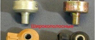
There are two types of phase sensors - slot and end. They have different shapes, but work on the same principle. So, on the surface of the camshaft there is a mark (another name is a benchmark), and during its rotation, a magnet included in the sensor design records its passage. A system (secondary converter) is built into the sensor body, converting the received signal into information “understandable” for the electronic control unit. End sensors are designed in such a way that there is a permanent magnet at their end, which “sees” the passage of a benchmark near the sensor. In slot sensors, the use of the letter “P” shape is implied. And the corresponding reference point on the distribution disk passes between the two planes of the housing of the slotted phase position sensor.
In injection gasoline engines, the master disk and the phase sensor are adjusted in such a way that a pulse from the sensor is generated and transmitted to the ECU at the moment the first cylinder passes its top dead center. This ensures synchronization of fuel supply and the moment of spark supply to ignite the air-fuel mixture. Obviously, the phase sensor has a direct impact on the operation of the engine as a whole.
What is he like?
The phase sensor operates on the principle of an elementary Hall sensor. Installed only in the camshaft area on both 8 and 16 valve engines. The device reads data from the engine camshaft using a gear mounted on the shaft with two missing teeth. These two teeth are positioned so that every time the device is hit, the first piston of the engine is at top or bottom dead center. Information signals about the location of the camshaft are sent to the engine control unit, which, in turn, monitors and changes the ignition angle. It began to be used at VAZ factories on the first cars with distributed fuel injection.
It is worth noting that carburetor engines do not have this unit, because their ignition timing system is vacuum-mechanical.
The main function of the camshaft position DF or phase sensor is to constantly adjust the ignition angle while the engine is running. Thanks to its use, VAZ family engines began to transmit power more efficiently with reduced fuel consumption. The main indispensable use of the phase sensor remains for two camshaft, 16-valve engines, which without it cannot operate evenly and economically according to the folded factory design.
Signs of a faulty phase sensor
If the phase sensor fails completely or partially, the electronic control unit forcibly switches the engine to paraphase fuel injection mode. This means that the timing of fuel injection is carried out according to the readings of the crankshaft sensor. As a result, each fuel injector injects fuel twice as often. This ensures that a fuel-air mixture is formed in each cylinder. However, it is not formed at the most optimal moment, which leads to a drop in engine power, as well as excessive fuel consumption (albeit small, although this depends on the specific engine model).
Symptoms of a faulty phase sensor are:
- fuel consumption increases;
- the toxicity of exhaust gases increases, the smell of exhaust gases will be felt, especially if the catalyst is knocked out;
- the engine begins to operate unstably, most noticeably at low (idle) speeds;
- the acceleration dynamics of the car, as well as the power of its engine, are reduced;
- the Check Engine warning light is activated on the dashboard, and when scanning errors, their numbers will be associated with the phase sensor, for example, error p0340;
- at the moment the engine starts in 3...4 seconds, the starter spins the engine “idling”, after which the engine starts (this is due to the fact that in the first seconds the electronic control unit does not receive any information from the sensor, after which it automatically switches to emergency mode, based on data coming from the crankshaft position sensor).
In addition to the above symptoms, often when the phase sensor fails, problems arise with the vehicle’s self-diagnosis system. In particular, at the moment of starting, the driver is forced to turn the starter for a little more time than usual (usually 6...10 seconds, depending on the model of the car and the engine installed on it). And at this time, self-diagnosis of the electronic control unit occurs, which leads to the formation of corresponding errors and transfer of the engine to emergency operation mode.
Malfunctions of the phase sensor on a car with HBO
It is noted that when the engine is running on gasoline or diesel fuel, the unpleasant symptoms described above do not appear so acutely, which is why many motorists often use cars with a faulty phase sensor for a long time. However, if your car is equipped with gas equipment from the fourth generation and higher (which uses its own “smart” electronics), then the engine will work intermittently, and the driving comfort of the car will sharply decrease.
In particular, fuel consumption will increase significantly, the air-fuel mixture may be lean or, conversely, enriched, and engine power and dynamics will significantly decrease. All this happens due to a mismatch between the software of the electronic engine control unit and the LPG control unit. Accordingly, when using gas-cylinder equipment, the phase sensor must be changed immediately after its breakdown is detected. Using a machine with a damaged camshaft position sensor is harmful in this case not only to the engine, but also directly to the gas equipment and its control system.
Determination of DF failure
If it breaks down, minor problems arise with idle stability; when starting to move, a trimming effect is possible, as well as increased fuel consumption. These symptoms are associated with the failure to receive on-board computer data on the ignition angle at a certain point in engine operation. If there is no signal from the sensor, the control unit enters emergency mode, that is, it begins to work on a predetermined program without a sensor and issues an emergency error “0340” or “0343”.
Causes of malfunction
The main reason for the malfunction of the phase sensor is its natural wear, which occurs over time for any part. In particular, due to exposure to high temperatures from the engine and constant vibration in the sensor housing, its contacts are damaged, the permanent magnet may demagnetize, and the housing itself may be damaged.
Another main cause is problems with the sensor wiring. In particular, the power/signal wires may be broken, which is why no supply voltage is supplied to the phase sensor, or a signal does not come from it via the signal wire. It is also possible for the mechanical fastening on the “chip” (the so-called “ear”) to break. Less often, a fuse that is responsible, among other things, for powering the phase sensor may fail (for each specific car it will depend on the complete electrical circuit of the car).
How to check the phase sensor
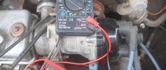
Checking the functionality of the internal combustion engine phase sensor is carried out using a diagnostic tool, as well as using an electronic multimeter capable of operating in DC voltage measurement mode. We will discuss an example of a test for phase sensors of a VAZ-2114 car. On models with a 16-valve engine, a sensor model 21120-3706040 is installed, and on 8-valve engines - 21110-3706040.
First of all, before diagnostics, the sensors must be removed from their mounting location. After this, you need to visually inspect the DF housing, as well as its contacts and terminal block. If there is dirt and/or debris on the contacts, it must be removed with alcohol or gasoline.
To check the sensor of the 8-valve engine 21110-3706040, it must be connected to a battery and an electronic multimeter according to the diagram shown in the figure.
Next, the verification algorithm will be as follows:
- Set the supply voltage to +13.5±0.5 Volts (you can use a regular car battery for power supply).
- In this case, the voltage between the signal wire and ground must be at least 90% of the supply (that is, 0.9V). If it is lower, and even more so equal or close to zero, then the sensor is faulty.
- Bring a steel plate to the end of the sensor (with which it is directed towards the camshaft reference).
- If the sensor is working properly, then the voltage between the signal wire and ground should be no more than 0.4 Volts. If more, it means the sensor is faulty.
- Remove the steel plate from the end of the sensor, the voltage on the signal wire should again return to the original 90% of the supply voltage.
To check the phase sensor of a 16-valve engine 21120-3706040, it must be connected to a power supply and a multimeter according to the diagram shown in the second figure.
To test the corresponding phase sensor, you will need a metal piece with a width of at least 20 mm, a length of at least 80 mm and a thickness of 0.5 mm. The verification algorithm will be similar, however, with other voltage values:
- Set the supply voltage on the sensor to +13.5±0.5 Volts.
- In this case, if the sensor is working properly, then the voltage between the signal wire and ground should not exceed 0.4 Volts.
- Place a pre-prepared steel piece into the sensor slot where the camshaft reference is placed.
- If the sensor is working properly, then the voltage on the signal wire should be at least 90% of the supply voltage.
- Remove the plate from the sensor, and the voltage should again drop to a value of no more than 0.4 Volts.
In principle, such checks can be performed without removing the sensor from its mounting location. However, to inspect it, it is better to remove it. Often, when checking a sensor, it makes sense to check the integrity of the wires, as well as the quality of the contacts. For example, there are cases when the chip does not hold the contact tightly, which is why the sensor does not receive a signal to the electronic control unit. Also, if possible, it is advisable to “ring” the wires going from the sensor to the ECU and to the relay (power wire).
In addition to checking with a multimeter, you need to check for relevant sensor errors using a diagnostic tool. If such errors are detected for the first time, you can try to reset them using software, or simply by disconnecting the negative terminal of the battery for a few seconds. If the error appears again, additional diagnostics are needed using the above algorithms.
Typical phase sensor errors:
- P0340 - no camshaft position sensor signal;
- P0341 - valve timing does not coincide with the compression/intake strokes of the cylinder-piston group;
- P0342 - the signal level in the electrical circuit of the DPRV is too low (detected when there is a short to ground);
- P0343 - the signal level from the meter exceeds the norm (usually occurs when the wiring is broken);
- P0339 - an intermittent signal is received from the sensor.
Thus, if these errors are detected, it is advisable to perform additional diagnostics as quickly as possible so that the engine operates in optimal operating mode.
Replacement instructions
Below we will tell you how to replace the DPRV when faults are identified. Replacement on engines with 8 and 16 valves is slightly different; let’s look at this process step by step.
Replacing the DF on an 8-valve engine
- The DPRV or DF is mounted on one bolt; this bolt is unscrewed using a 10mm wrench.
- After unscrewing the bolt, the DPRV can be dismantled. In this case, the connector into which it is installed must be closed to prevent dirt and dust from getting into it.
- Carry out diagnostics of the regulator. If there are traces of dirt on it, they must be removed by wiping the DF dry. After this, put the DF back in place and try to start the engine again. If this does not help, you need to replace the DPRV.
Sometimes it happens that after replacing the DF the problems do not disappear. This happens very rarely, but this problem may be due to the fact that the control gear has moved. You won’t be able to solve this problem with your own hands; you will have to resort to the help of specialists. In some cases, errors in the operation of the DF appear as a result of incorrect installation of the timing belt. Also, the belt may simply be more stretched, which means it needs to be replaced.
Replacing the DF on a 16-valve engine
As for 16-valve internal combustion engines, in this case the process of removal and replacement will be slightly different:
- The DPRV is installed under the air manifold, directly next to the camshaft. For a more convenient replacement, it is necessary to dismantle the radiator grille.
- Using a wrench (specifically a socket extension), remove the two retaining bolts.
- Check the operation of the DPRV, clean it, try installing it again. If this does not help get rid of the problems, then proceed with replacement.
- To install a new DF, you cannot use sealants, since the device always operates in an aggressive operating environment, because the temperature on the cylinder head is constantly changing. Replacing a VAZ 2114 with a 16-valve engine takes a little longer, but the procedure is generally similar to an 8-valve internal combustion engine.
Functionality check
After replacing the DPRV device, you need to make sure that everything is working correctly and correctly. Otherwise, replacement may become an impractical exercise.
To check the regulators, follow these steps:
- Connect the battery and start the engine.
- Using a scanner or turning on self-diagnosis mode, check the control unit for errors.
- Listen to how your car's engine works. The motor should operate normally, no extraneous sounds or other symptoms of breakdowns.
Features of checking and replacing the VAZ 2114 phase sensor
The VAZ 2114 camshaft sensor is one of the most important measuring instruments of the fourteenth, which, through a pulse signal, transmits information about the current engine operating cycle to the car’s brains. Based on the information received, the electronics adjusts the timing of supply and ignition of the fuel mixture in the engine cylinders.
A normally functioning DF is the key to the correct functioning of the engine, which achieves the optimal ratio of the amount of fuel consumed and the operating power of the power unit.
From this article you will learn the main causes of DF malfunction and how the failure of the device affects the operation of the car. The technology for replacing the DF on the VAZ 2114 will also be examined in detail.
Features of the VAZ 2114 phase sensor
REASONS AND SIGNS OF MALFUNCTION
You can determine that the phase sensor on a VAZ 2114 has failed by the following malfunctions in the vehicle:
- Gasoline consumption has increased significantly;
- The acceleration dynamics of the fourteenth have worsened, and dips are observed in the engine’s idle speed;
- The engine idles;
- Errors No. 0343 and 0340 are displayed on the on-board computer screen, which indicate that the DF is faulty and the ECU is operating in emergency mode.
The reason why the phase sensor failed can be determined only after dismantling and visual inspection of the device, in some cases - after diagnosing it. As a rule, the main causes of DF failure are as follows:
- A short circuit has occurred on the internal DF circuit;
- Mechanical damage to the device mounting ears, due to which the housing has shifted in the mounting socket;
- The toothed disk on the pulse signal converter has broken;
- The DF was damaged due to the increased temperature of the engine.
PHASE sensor
If the device breaks down, the ECU starts working exclusively on the readings of the crankshaft sensor. In this mode of operation, it is impossible to carry out phased fuel injection, as a result of which the brains of the fourteenth switch the engine to twin injection, which results in excessive consumption of gasoline and deterioration in acceleration dynamics.
Repairing the device in most cases is not advisable, since a DF that has once failed is unlikely to work normally in the future.
Fortunately, the cost of DF is low - the price of a new device is 400-600 rubles, depending on the manufacturer (prices are also relevant for sensors on the VAZ 2115).
CHECKING PERFORMANCE
If typical signs of DF failure occur, or if errors 0343 or 0340 are displayed on the on-board computer of the fourteenth, it is necessary to check the functionality of the DF. This is done using a conventional multimeter.
Fourteeners with 16 and 8 valve engines have different DFs, so the specifics of checking them will be slightly different.
How to check the camshaft sensor VAZ 2114 8v:
- On the first probe of the tester we set the voltage to 13.5 Volts and connect it to contact “E” on the DF, on the second probe, which must be connected to contact “B” - 0.9 V;
- Having closed the contacts, we bring a metal screwdriver to the end of the sensor. If the DF is working properly, you will see on the tester screen that the voltage of contact “B” has dropped to 0.4 Volts. If this does not happen, the DF is broken;
How to check the camshaft sensor VAZ 2114 16v:
- We set the following voltage on the multimeter: contact “E” – 13.5 Volts, “B” – 0.4 Volts;
- We close the contacts and insert a screwdriver into the hole on the phase sensor. If the device is working properly, the voltage at pin “B” will increase to 0.9 Volts.
A multimeter is a standard device for checking the performance of any sensor
WE REPLACE THE PHASE SENSOR
Having determined that the DF is faulty, you can begin to replace it. The process is easy enough that you will only need a ratchet wrench with a 10 mm head to do all the work yourself.
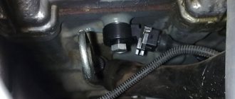
First, let's figure out where the VAZ 2114 phase sensor is located. It is located on the right side of the engine compartment, near the air filter. It is secured to the cylinder block body with one screw.
Replacement of the VAZ 2114 phase sensor is carried out in the following sequence:
- Open the hood and disconnect the power terminals from the fourteenth battery;
- Disconnect the wire block from the DF;
- Using a 10mm wrench, unscrew the screw fixing the sensor on the cylinder block;
- We remove the DF from the mounting socket.
After dismantling the old device, inspect it visually; perhaps the cause of its malfunction is metal dust magnetized on the DF body. If found, wipe the device with a cloth and reinstall it. If it does not come to life and the on-board computer continues to generate errors, the sensor needs to be replaced.
The new camshaft position sensor of the VAZ 2114 is installed in a similar way. As you can see, the work here only takes 10-15 minutes (replacing the VAZ 2115 phase sensor is carried out using the same method).
Important: when installing the DF into the mounting socket to seal the fixation, it is prohibited to use any sealing agents, since the device is located in an environment with a constantly changing temperature regime, in which the sealant will simply melt and bring you a bunch of additional troubles with the engine.
There are often cases when, even after installing a new DF, errors 0350 or 0343 continue to be displayed on the on-board computer of the fourteenth.
There are two possible scenarios for the development of events. You may have come across a faulty DF (even salespeople in auto stores say that if for 10 domestically produced phase sensors there are 5 workers, without manufacturing defects, this is already good).
Checking the functionality after replacement is carried out using a multimeter, as described in the previous section of the article. If the tester data corresponds to the indicators of a fully working sensor, then the problem is not with it. Errors 0350 and 0343, indicating a faulty DF, can also occur due to a timing belt that is stretched or has slipped by 1-2 teeth, or a loose crankshaft gear.
Location of the DPRV on the engine
To check the camshaft position sensor, you need to know where it is located. As a rule, on eight-valve engines the DPRV is usually mounted at the end of the cylinder head. On sixteen-valve engines it is also mounted on the cylinder head, usually in close proximity to the first cylinder.
As for popular domestic VAZ cars, their owners call such units phase sensors. Their location in these motors is similar. So, on eight-valve engines, the sensor is located on the left side of the cylinder head (when viewed in the direction of travel of the car).
On sixteen-valve engines - on the right front part of the engine. In the latter case, the sensor is not directly visible visually; its location can only be assessed by the signal and power wires suitable for it. The VAZ 2114 phase sensor is fixed in close proximity to the air filter, near the cylinder head.
Phase sensor VAZ 2114 8 valves signs of malfunction
The phase sensor, also known as the camshaft position sensor (hereinafter referred to as CF), is an element of the ECU (electronic on-board engine control) system, which is present exclusively in injection-type engines. This sensor is equipped with all fourteen engines with a 16-valve engine, as well as 8-valve engines that comply with the Euro-3 standard and have sequential phased injection of the fuel mixture.
From this article you will learn the principle of operation of the DF, typical problems that can arise with the device during operation and their symptoms, as well as phase sensor errors on the VAZ 2114 and their interpretation.
Phase sensor for VAZ 2114
DESIGN FEATURES AND OPERATING PRINCIPLE
The VAZ 2114 FAZ sensor is an integrated device, the main function of which is to receive information about the current operating cycle of the power unit and transmit it to the ECU via pulse signals.
Structurally, the DF consists of two parts - a sensitive element and a pulse signal converter, which in turn consists of an operational amplifier, a bridge circuit and an open-collector type output stage.
The DF sensitive element operates according to the Hall principle; it is a microcircuit that responds to fluctuations in the magnetic field, which gains the ability to transmit an electrical signal only when there is a magnetically conductive material next to it, which is the steel head of the valve.
The location of the VAZ 2114 camshaft position sensor is as follows: it is located on the end of the cylinder block, not far from the air filter.
Location of DF
There is a lot of discussion on the Internet about which phase sensor is best to buy from which manufacturer. We recommend giving preference to devices from the German company Bosch. It is she who has the license to manufacture sensors operating on the Hall principle, so, in essence, you get a reliable and durable device produced by the direct owner of the technology by which it is made.
SYMPTOMS AND INSPECTION
Signs of a malfunctioning camshaft sensor, by which you can determine that the device has failed, are as follows:
- Increased fuel consumption;
- Problems in the vehicle self-diagnosis mode;
- Reduced acceleration dynamics;
- The “Check Engine” sign or errors 0343 or 0340 appear on the dashboard.
The “Check Engine” icon, as a rule, lights up when the DF is completely out of order. The following happens: you turn on the ignition, after which the starter starts working, at this time the ECU unit should receive a signal from the sensor, but since the DF is broken, it is not there, and the electronic control switches the engine to twin injection mode (based solely on the data received from the DKPV ), turning off the phased injection of the fuel mixture.
If you find any signs of malfunction, you need to check the DF. You can do this yourself; you only need a tester (multimeter), which can be purchased at any car store for 400-600 rubles. The device is inexpensive, but useful - you will need it several times when diagnosing a car.
On fourteenths with a 16-valve engine, DF models 21120-3706040 are installed, on 8-valve engines - 21110-3706040. Checking each of them has some features.
Scheme (for 8th grade)
- On the multimeter probe (V1 mode), which will be connected to contact “E” on the sensor, set the voltage to 13.5 V, on the second probe (connect to contact “B”) - 0.9 V;
- We close the probes on the corresponding contacts. We bring a metal plate to the end part of the DF (a screwdriver will do). If the device is working normally, the multimeter will show that the voltage at pin “B” has dropped to 0.4 V (should return to 0.9 when the plate is removed). Differences in readings – the sensor needs to be replaced.
Checking the DF of a 16-valve engine:
Scheme (for 16 cells)
- We switch the tester to V2 mode. On the probe of contact “E” we set the voltage to 13.5 V, on contact “B” - 0.4 V;
- Insert a screwdriver into the hole at the end of the DF housing. When the sensor is working, the voltage at contact “B” will increase to 0.9 W and drop back if the screwdriver is removed.
DF ERRORS
If the VAZ 2114 is equipped with an on-board computer, if the device malfunctions, it will display one of the errors with code 0340 or 0343. Let’s analyze each of them in more detail.
- FAZ sensor error 0340 - indicates the absence of a DF signal. The cause of this error can be anything from oxidized contacts to mechanical damage to the device. Solved by replacing the part with a new one.
- Error 0343 – high signal level of the phase sensor. Its cause, as a rule, is damage to the wiring itself or the terminals in the contact block, or their loose/oxidized connection.
Errors in the VAZ 2115 phase sensor are completely similar to the errors that occur on the fourteenth.
It is worth noting that in addition to a malfunction of the DF itself, the cause of errors may be a slipped timing belt or a loose crankshaft gear.
REMOVAL AND REPLACEMENT
The phase sensor on the VAZ 2114 is a complex electronic structure, repairing which on your own will not give any meaningful results. If any problems are detected, you must immediately replace the device with a new one . Fortunately, it is not expensive: the price varies from 300 to 500 rubles, depending on the region.
To replace the DF you will need a ratchet wrench with a 10mm head. The algorithm of actions is as follows:
- Turn off the battery power;
- Using a ratchet, unscrew the bolt that secures the DF to the engine cylinder block and disconnect the block of wires connected to it;
- We take out the sensor and install a new one, do not forget to clean the contacts of the block from oxidation.
If the device is installed correctly, then all errors previously displayed on the on-board computer disappear.
As you can see, the work here takes about 10 minutes at most. Have a good ride without any breakdowns!
Verification Information
There are also simple recommendations here.
- The easiest option is to connect to a computer and check for ECU errors. After that, all that remains is to decipher the messages that appear. A decision is then made on the appropriate method to correct the fault.
- We connect the wires to the camshaft position sensor connectors. At the next stage, connect the multimeter.
- The check when the previous condition is met is carried out as follows: we need something flat, made of metal. This part is brought to the tip of the sensor. You need to look at the device, study the readings that change.
How to check the phase sensor of a VAZ 2114 with a multimeter
Checking the phase sensor 21110-3706040
It is necessary to set the voltage on the voltmeter V1 on the power supply E to 13.5 ± 0.5 V, the voltage at contact “B” of the sensor must be at least 0.9 Up. Next, we bring the plate to the end of the sensor and look at the operation of the sensor. It should work. This can be determined on contact B. When the sensor is triggered, the voltage on contact “B” should be no more than 0.4V. We remove the steel plate from the end of the sensor and measure the voltage again, it should change to a value of at least 0.9 Up.
Checking the phase sensor 21120-3706040
Set the voltage at voltmeter V2 on power supply E to 13.5±0.5V, the voltage at contact “B” should be no more than 0.4V. Bring a steel plate made of soft magnetic material with a width of at least 20 mm, a length of at least 80 mm and a thickness of 0.5 mm to the end of the sensor as shown in the figure, placing it in the slot of the housing. The voltage at contact “B” of the sensor must change and be at least 0.9 Up. Remove the steel plate, and the voltage at contact “B” of the sensor should change to a value of no more than 0.4V
Technical characteristics of the camshaft sensor 2111-3706040 engine 11183-30 (l.6i)
- Supply voltage, V – from 6.3 to 24;
- Maximum collector current, mA, no more – 40;
- The output circuit is open collector;
- Camshaft speed interval – from 10 to 4000;
- Gap between the end of the sensor and the marker, mm – 0.3 to 1.5;
- Connection/disconnection angle, degree angle – 12+9;
- Duration of fronts, μs, no more – 5;
- External dimensions of DPRV, mm – 24.4×46.5×53.5;
- Weight, g – 80;
- Operating temperature, °C – from minus 40 to +125;
- Relative air humidity for operation at a temperature of +40°C, % not more than – 95
- Atmospheric air pressure, mm Hg. Art. – from 630 to 800
What is the phase sensor responsible for on the VAZ 2114?
The camshaft sensor in the VAZ-2114, however, as in other modern cars, has a fairly important role. Correct fuel injection, and therefore its consumption, depends on its correct operation. This part was first installed on the VAZ “fourteenth” in 2007. Accordingly, before this, the design of the car did not provide for the presence of a camshaft sensor. Considering the fact that the manufacturer nevertheless decided to supplement the design of the car with it, we can conclude that the use of this device provides some advantages.