Published: 10/20/2020
- Repair
- Methods for checking the ignition module of a VAZ 2114
- Repair
- How to disassemble the ignition module of a VAZ 2110
- Ignition module repair
- Version of the module on the 8-valve VAZ-2112
- We disassemble the design of the ignition module of a modern injector
- Checking module power
- Possible reasons for failure of the ignition module
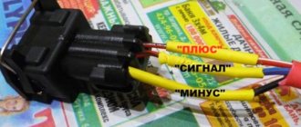
- Diagram of the correct connection of wires to the ignition module
- Connection diagram
- VAZ 2115 ignition module, description and malfunctions
Repair
The design of the ignition module is quite complex: it includes one or more coils, a board, contacts and wires. Of all the above elements, only contact connections can be repaired; in some cases, replacement of parts (transistors, coils) is possible.
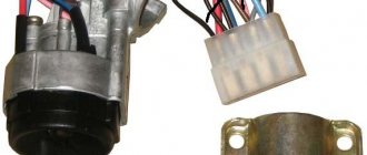
The module is dismantled and opened for repair purposes. For this you will need:
- Socket wrenches with heads 1, 13 and 17.
- Hexagon 5.
- Screwdriver.
- Soldering iron.
- Flux for aluminum.
- Stranded wire.
- Nail polish.
Repair of the ignition module is carried out in the following order:
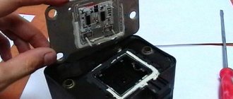
- On the removed device, open the case by prying it off with a screwdriver.
- Remove the silicone film covering the board.
- All aluminum is removed from the explosive contacts.
- On the board, new wires are soldered in place of all the dismantled old ones. To do this, the surface of the collector is cleaned of deposits, after which the board is heated to 180°C (a characteristic smell will indicate when the desired temperature has been reached). During the soldering process, the ends of the wires are connected to the module.
- At the end of the operation, all contacts, the board and the module are covered with nail polish.
- The device is assembled in the reverse order, installed on the car and the engine is started. In case of normal operation, the ignition module is sealed tightly with sealant, while the wires are tucked inside the cavity so that they are not pinched at the edges by the plate.
If the device does not work, then a breakdown inside the module should be looked for more carefully. The transistor, electronic component may have failed, or there may be a break in the coil. Such a repair makes sense only if its price is significantly lower than the cost of a new part.
Signs
- If one of the module coils completely fails, then two cylinders do not work. This is clearly visible even to the naked eye - the engine is feverish at idle, starting is difficult, fuel consumption is sky-high, loss of dynamics.
- To eliminate all other components of the ignition system, make sure that the spark plugs are in working order. To do this, unscrew them and check the spark on each of the spark plugs by cranking the engine with the starter and placing the spark plug with the high-voltage wire on the head so that the body (threaded part) of the spark plug touches the engine mass. If there is no spark or it is weak, replace the spark plug with one that is known to work.
- If this does not lead to anything, check the high-voltage wires. Thus, we will exclude spark plugs, caps and high-voltage wires from the list of non-working elements. Next we will check the ignition module.
Breakdown of the spark plug insulator.
Dirty spark plug electrodes.
Filled candles.
Methods for checking the ignition module of a VAZ 2114
There are several ways to find out if the module is working properly. Many car enthusiasts are wondering about checking the ignition module of the VAZ 2114, because there are several types of system for this model. Therefore, not each of them is suitable in structure and structure. The first of these options is quite effective and often used. First, you need to use another working module and try to start the engine with it, this will help you find out for sure whether the previous one is broken.
However, it is worth considering that there are different types of modules for a given type of car, so you need to use the one that is suitable. If the engine does not work properly with another module, then the old one needs to be replaced. If the problem is still in damaged wires, then there is a high risk of damaging another component. To prevent this situation, you need to inspect the wires for damage before checking. However, to do this, you need to know how to ring the ignition module to ensure that the wires are working properly and functioning properly.
Ignition module VAZ 2114
Using a Multimeter
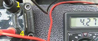
All you need to do is use a multimeter that is set to voltmeter mode. After which you need to disconnect the ignition module and coil. Next, you need to carry out some manipulations with the contacts called “A” and the engine ground. Try starting the engine and look at the multimeter readings. They should not exceed 12 V. Carry out similar actions with the second contact. Other indicators besides those indicated may be the result of a malfunction or breakage of high-voltage wires. However, in some cases, the current may not flow or flow, but in small quantities because the fuse has blown.
It is worth noting that this vehicle model has three fuses that trigger the spark plugs. Therefore, to exclude this option, it is necessary to check the proper functioning of the fuses. After all, the proper operation of the engine depends on each component of the whole mechanism. However, in order to check the ignition module with a multimeter, you need to make sure that the wires through which high voltage enters the module do not contain damage or cracks. After all, this entails damage to the entire diagnostic process.
Diagnostic algorithm
Nevertheless, before checking the ignition module on the VAZ-2114, it is worth familiarizing yourself with the algorithm of actions that need to be performed during further diagnostics. This algorithm includes the following items:
- The high-voltage circuit checks the ignition module for breaks;
- inspection and testing is carried out by tugging and tapping (a similar method is most often used by car enthusiasts to check the serviceability of parts and components of the mechanism).
In the case of the first point, take a multimeter configured to determine resistance. Since the connections in the ignition coil are parallel, the resistance that exists between them must be at a certain level. Otherwise, when the readings are different, it may mean that a break has occurred. In this situation, the model cannot be repaired and must be replaced. For the second point, such actions are the norm, despite the fact that it sounds a little not serious.
However, after these procedures, there is a possibility that the component will begin to function, albeit for a short period of time. Still, after this you need to go to a specialized vehicle store and buy a new component.
To avoid such situations, it is necessary to do regular inspection of your mobile vehicle. Also carry out checks to ensure that important engine parts, such as the ignition module, are in good working order. After all, it is thanks to him that your car starts and drives stably. Most often, specialists working in auto shops can advise clients on issues that interest them, as well as provide recommendations in the selection of parts.
Video on repairing KZ VAZ
There were no prerequisites for replacement. The original coil worked fine, well, almost normal. I didn’t like that the car was adjusting under constant load. Therefore, I decided to conduct an experiment on replacing the coil with something larger and more interesting. I looked at Oleg reekardo’s blog about replacing the coil and decided to go the same route, but make it a little more complicated. Without thoroughly reading the entry (and it says to buy a coil, not an ignition module from a VAZ), I went and first bought an ignition module and a connector for it. The same module was in my Niva.
I started connecting it, but it didn’t work—the car wouldn’t start. I built a mini test bench (4 spark plugs, wires and battery). The stand showed that the module was working. (And it was written to take a coil, not a module) I went and replaced the module with a coil (I also got the difference in price in my pocket 
Then it's easier. I found the necessary connection points and checked the operation. Then I soldered the wires to the original wiring. The original connector was wrapped with electrical tape. I mounted the module diagonally on the standard plate, just removed the wire fastening to the knock sensor and screwed the bolt into the vacant hole.
Repair
So, for the VAZ 2110 the most common problem is the disappearance of voltage on cylinders 2 and 3. After some time, the engine starts working normally again if you press the rear plate of the module.
You should not put up with such a situation; it is better to immediately check the functionality of the unit, restore or replace it completely.
Removing the module
The procedure is quite simple.
- Disconnect the negative cable from the battery.
- Remove the plastic cover that covers the motor.
- Remove the wires from the spark plugs.
- Disconnect the wires from the ignition module. Their numbering is indicated on special white rings. And the cylinder number is indicated on the ignition module housing.
- Disconnect the connector from the ignition module.
- Using a 10mm socket, unscrew the three nuts that hold the block we are looking for.
- Carefully remove it, after which you can begin further work.
Now let's move directly to working with the module:
- Open the aluminum plate on the ignition module. A flathead screwdriver is useful for this.
- Inside you will find a small printed circuit board with electronic components. It is covered with a transparent layer of silicone, which will have to be removed.
- There are also wires that connect the board to the connector contacts. They are made of aluminum, so they can tear quickly.
- Tear off all the wires from the contacts, don’t be afraid. Others will be installed in their place. By the way, experts recommend using stranded wires used in computer mice.
- The ignition module circuit includes two switches and two powerful transresistors. If you decide to change these elements, you need to know that the switches are manufactured by SGS-THOMSON (model L497D1), and the transistors are of the BU931 type.
- The contacts are made of aluminum, so you will need a special flux to work with this metal.
- We solder the wiring to the board. It is more difficult to solder to the transistor collectors, since they are covered with a special material, the soldering of which is problematic. Therefore, try to hide the top coating from the element as carefully as possible. To prevent the soldering iron from transferring all the heat to the plate, place it on the stove and heat it to 180 degrees Celsius.
- Solder the wires to the contacts on the module so that they are as short as possible.
- Cover the areas where you soldered with varnish. Regular nail polish borrowed from your wife will do.
- Check if the ignition module is working.
- If everything is fine, coat the inner surface with a special autosealant, then reassemble in the reverse order.
- Upon completion of assembly, the wiring should be positioned fairly freely. Make sure that they are not compressed inside the box and that the integrity of the connections is not broken.
Carrying out a similar repair of the ignition module on a VAZ 2110 with your own hands will not be difficult.
But be careful, act carefully and consistently
Pay special attention to the soldering process
But keep in mind that we have addressed the problem of bad contacts. She is not the only one for the “ten”. You may need to pinout the ignition module on the VAZ 2110. For this, it is better to contact specialists.
If the cause of the malfunction lies elsewhere, then there is a high probability that it is better to simply replace the VAZ 2110 8-valve ignition module with a new one. The search may drag on without yielding results. Replacing the element will completely solve the current problem.
Possible causes of failure
The weak point of the ignition coils and modules is the secondary winding, which generates a high voltage pulse. A coil break or breakdown may occur in it. The following factors lead to this phenomenon:
- use of low-quality or unsuitable candles;
- operation with non-functioning high voltage wires;
- frequent attempts to check the spark.
The high-voltage pulse arising in the secondary winding must be realized (spent). If this does not happen (if the integrity of a high voltage wire is broken, for example), a high-energy electrical pulse seeks an outlet. He will find it, with a high degree of probability, in the thin secondary winding.
Often, a module malfunction occurs when the integrity of poor-quality factory soldering of wires going to the switch elements is violated. This happens from vibration. Also, the cause of non-working coils can be a banal contact failure in the incoming connector. Another factor leading to a malfunction of the ignition unit is often moisture that gets on the device during washing or driving in unusual conditions.
How to disassemble the ignition module of a VAZ 2110
Many car owners are faced with the problem of their car not starting. If it suddenly turns out that high voltage has disappeared on the cylinders (either only on one, or on several at once), or the warning lamp does not light up, there is no spark, then the engine will not work. The ignition module may have failed. It's not always worth rushing to stores to look for something new.
Those who own a VAZ-2110 car are offered an alternative - repairing the ignition module themselves. The main thing is to have basic knowledge of auto electricians and the ability to understand circuits and contacts. It’s also a good idea to know how to use a digital multimeter in your work.
In order to disassemble the ignition module, you will also need knowledge of its components. This is a pair of ignition coils designed to excite high-voltage pulses, and a two-channel switch. Basically, high-frequency pulses can disappear in the 2nd and 3rd cylinders. You will have to start by removing the ignition module. The high-voltage wires are disconnected, then the VAZ-2110 ignition module itself is removed.
Unscrew the bolts
We get the board
Reassembling the sensor in reverse order
The essence of the repair is as follows:
To open the aluminum plate you will need a straight screwdriver. Looking at the inside of the module, it may seem that everything is very complicated. Attention should be paid to the printed circuit board, which is coated with transparent silicone. The sealant is removed. To make the wires with which the board is connected to the contacts of the connectors and coils, too soft aluminum is used, so they become unusable. Such wires are torn off and thrown away. What should I put in place? You will need a computer mouse, which will have to be disassembled. It only requires stranded wires. The ignition module circuit includes two L497D1 switches, which are also manufactured by two fairly powerful transistors. The contacts are aluminum, so for soldering you will need a special flux for aluminum. First, the wires are soldered to the board itself. During manufacturing, the collectors are coated on top with a special metal that cannot be soldered. Therefore, before soldering the wires, the coating is removed from the metal. Then the plate is placed on the stove and heated to one hundred and eighty degrees, the heat will be distributed throughout the plate
This is important so that when the soldering iron comes into contact with the plate, the heat does not dissipate from it. Now you can proceed directly to soldering the wires to the module contacts. Try to make the wires as short as possible.
Next, take a varnish (the varnish you use to paint your nails will also work), and use it to insulate the joints. Next, you need to check the ignition module. It must be functional. And the final touch: the inner surface is coated with autosealant, after which the assembly is completed. The wires should be positioned freely and not be pinched.
The work is not that difficult, and can be done by anyone who can work with a soldering iron and have basic knowledge of electronics.
If after repair it turns out that the cause of the malfunction was different, then this reason needs to be found, or go to the store for a new module.
Module design
Before you begin repairing the ignition module, it is worth understanding what it consists of. So, let's look at the design of this element:
- Two ignition coils generate a high voltage pulse.
- Dual channel switch.
If there are problems with the operation of the ignition module, there are reasons for this. It is worth warning that with this malfunction the “Check Engine” lamp does not light up: engine stops, loss of spark, interruptions in the operation of the power unit, etc.
Diagnosis and repair require basic knowledge not only of conventional electrical installation, but also of the principles of automotive electrical installation. In addition, the process will require skills in using a digital multimeter to be successful.
Repair process
Often the high-voltage pulse is lost in cylinders 2 and 3. So, in order to begin repairing the ignition module, of course, you will have to disassemble it. To do this, disconnect the high-voltage cables and unscrew the assembly itself from the supports. When the preparatory operations are completed, you can proceed directly to the repair process:
- We tear off the aluminum plate.
Open the aluminum plate with a screwdriver
Wire welding diagram and arrangement of elements on the boards
Diagram of the assembled ignition module
Fully assembled ignition module
Video about repairing the ignition module on a VAZ-2112
The video will tell you about repairing the ignition module and how to remove it from the car.
Ignition module repair
If the ignition module does not work, you can try to rehabilitate it:
- Take 10, 13 and 17 end keys, a 5 hex key, a regular screwdriver, a soldering iron, aluminum flux, nail polish, and stranded wires.
- Most often, the connection in the ignition system deteriorates - those same contacts.
- We turn the key in the ignition, start it, move the contacts, and get a comprehensive answer in the absence of their quality connection.
- Now we turn off the engine and remove the ignition module out.
- You need to open it, pry up its body with a screwdriver.
- Inside the board is covered with silicone film - remove it.
- We remove all aluminum from the explosive contacts.
- Now comes the hard part: we need to solder new wires to the plan from where we just removed the old ones.
- First, you need to clean the surface of the collector from plaque, then put the board on the stove and heat it to 200 degrees (approximately by eye, of course), it will start to smell a little when it reaches the desired temperature and soldering on it will become much easier.
- Now, actually, we solder: we connect the ends of the wires to the module.
- We cover all the contacts of the wires with the module and the board with nail polish.
- Now you need to put everything back together, put the ignition device in place and start the engine. Only after this, when you are convinced that everything is working properly, can you take the sealant and seal it tightly.
- Individual elements that have failed. They cannot be repaired, they are only for replacement. Fortunately, the price for them is adequate: a switch is within 200 rubles, a transistor is from 200 to 300 rubles.
A very important point: in common parlance, as here, the ignition coil and the ignition module are synonyms. But in terms of technical design, no. For fourteenths with different engine sizes, different spare parts are installed: for 1.5-liter Samaras of the old generation, it is the ignition module, and for 1.5 and 1.6 liters of the new generation Samaras, it is the ignition coil. The switch of the new type of machines is hidden in the electronic control unit, it turns out that the module was broken, and they began to call it by the name of its main part - the coil. Be careful when choosing a spare. parts from disassembly: do not confuse them, given this fact.
If we talk about service, the price is not worth the cost. It’s easier to figure everything out yourself, even more so. That there are a lot of resources where they can give you advice and help. The main thing is to remember the layout of the high-voltage wires and their good contact. It happens that incorrectly connected wires contribute to improper combustion, a spark hits the relay. And the ignition module completely burns out.
The process of checking all ignition coils on a VAZ-2112
The VAZ-2112 engine with 16 valves uses individual Bosch ignition coils and in order to check them, the following procedure must be followed:
- First of all, we remove each coil from its landing well.
- Then we turn off the power supply and remove them all together as an assembly.
- First of all, we pay attention to its external condition, the absence of cracks and various breaks.
- The same applies to the spring located inside the coil, look at its position, it should be exactly in the center.
Despite the fact that many people on the Internet talk about the impossibility of checking a coil with their own hands, it is possible to check it only by knowing their initial values, which are measured in ohms .
- In order not to make false measurements, first of all we check the internal resistance of the wires and the multimeter itself . To do this, switch the device to the OM position and connect the probes to each other. What value the multimeter gives is its internal resistance. The value can range from 0.0 to 0.3 ohm.
- First of all, we “ring” the primary winding, which is located on the first and third contacts; when connecting, the polarity does not matter.
- Depending on the presence of error readings and coil readings, we add up the final indicators. For example, if the internal resistance is 0.2 ohms and the coil value is 0.7 ohms, therefore the correct value would be 0.5 ohms. Which is the norm.
- We continue diagnostics with each of the coils.
- If it happens that there are no indications, then we once again check the quality of the connections and the correctness of the connection. If the readings are still zero, then the primary winding on this coil is faulty.
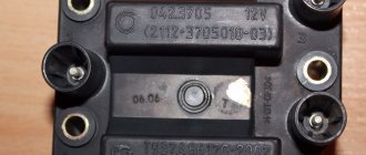
Version of the module on the 8-valve VAZ-2112
Two 8-valve engines of different volumes were installed on the twelve-wheeler - 1.5 and 1.6 liters. The ignition modules for these engines are different. The one and a half liter engine has a module with article number 2112-3705010, and the 1600 cc engine is equipped with a module 2111-3705010. A module for a 1.5 liter engine costs about 1500-2100, and the second one is 500 rubles cheaper.
Module structure
It consists of two ignition coils and two high-voltage switch switches. The coils are designed to create high-voltage pulses.
In essence, it is a simple transformer that has two windings: a primary winding, with an induction voltage of approximately five hundred Volts, and a secondary winding, with an inductive voltage of at least twenty kiloVolts. Everything is placed in one housing with one connector for signal wires and four for high-voltage.
Structure of the ignition coil module of the VAZ 2112
The operation of the ignition module is based on the “idle spark principle”. The module is capable of distributing a spark in pairs: to the first and fourth, second and third cylinders when transmitting pulses from the electronic control unit.
A little about prices
We have already noted which switch and transistor are used when repairing the ignition module of a dozen. The first costs about 3 dollars, and for the second you will have to pay about 6 dollars.
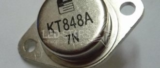
Some craftsmen use a domestic analogue of the transistor - model KT848A . Of course, it costs less. But its problem is its lower quality and larger size, which somewhat complicates the repair process.
We disassemble the design of the ignition module of a modern injector
As an example, consider a similar device used on injection VAZ cars. The module operates according to the good old principle: 12 volt power is supplied to the input, and a high voltage is generated at the output contacts for sparking.
The control is electronic, but the operating principles differ from a simple distributorless ignition system:
- All components are located in one housing. On the one hand, this is convenient - fewer wires and contacts - lower probability of breakdown. On the other hand, if the ignition module burns out, it must be repaired; simply replacing the failed element will not work.
- The device is compact and can be conveniently placed in the engine compartment.
- The ignition module is powered at low voltage, which increases the reliability of the device.
- The cost of the finished device is low.
- This ignition module has two coils. This contributes to the survivability of the device - each transformer is loaded twice as much.
The secret of the module’s operation is as follows: it uses not four, but two coils for 4 cylinders. Masters of the old school call this device a two-spark bobbin. Alternating connection of each coil produces two sparks: working and idle. Due to proper distribution among the spark plugs, the idle spark is ignited at the moment when there is no air-fuel mixture in the corresponding cylinder.
The signal for sparking is given by the switch (acting as an electronic distributor). Before checking the ignition module, you need to make sure that control pulses are coming to the contact blocks from the switch.
This block is responsible for the so-called ignition advance, that is, it generates a signal at the right moment. The control pulse about the position of the crankshaft is issued by the Hall sensor, which also synchronizes the operation of the entire system.
How to carry out repairs
If a breakdown is detected, the damaged coil must be removed. To complete the work you will need a set of wrenches.
After installing the new module, engine operation is checked; additional ignition settings are not required.
Removing the module
To remove a faulty unit, you will need:
- Disconnect the battery from the on-board network and remove the air filter housing.
- Disconnect the high-voltage cables and wiring harness.
- Remove the 3 nuts that hold the assembly to the mounting pad.
Replacement features
You can install the coil without using a special tool. The ignition system of injection engines does not require any adjustments. The throttle position is adjusted in idle and maximum gas modes. In case of malfunctions, it is necessary to check and align the crankshaft position sensor to the marks on the drive pulley of external units.
Checking module power
Before testing the performance of the coils, you should make sure that a possible breakdown is not caused by a loss of power to the device. First, you need to try to simply restore contact by moving it several times or disconnecting/connecting the block of wires included in the connector. If such manipulation does not lead to improved engine performance, a tester (multimeter) is used to determine the quality of incoming pulses.
The block of wires is removed from the connector. On the block, each terminal (A, B, C, D) has a corresponding socket. Testing with the engine running is done as follows.
- The first contact of the tester is in socket D, the second is to ground. The multimeter switch position is 20 volts. If there is power, the tester shows 12 volts.
- The first contact is in socket C, the second is ground. Switch on ohmmeter (20 Ohm). Normally it shows less than 1 ohm, that is, the mass is normal.
- The first contact is in socket B, the second is ground. 20 volt switch. The norm is not less than 0.3 volts. If this is so, it means that a normal pulse is coming from the Hall sensor to position B.
- Contact A is checked similarly to the previous one.
If such a check shows the norm, you need to test the module. If not, look for the cause in the electrical circuit to the coil.
Ignition coil diagram for VAZ 2112 16 valves
To do the job you will need a multimeter.
1. We prepare the car for work (see “Preparing the car for maintenance and repair”).
2. Remove the decorative trim of the engine (see “Decorative trim of the engine - removal and installation”).
3. Press the lock of the wiring harness block.
While holding the latch in this position, disconnect the wire block from the ignition coil of the first cylinder.
4. Turning on the ignition, use a voltmeter to measure the voltage at terminal 3 of the wiring harness block (the numbering of the terminals is marked on the ignition coil).
5. Similarly, we check the supply voltage to the ignition coils of the second, third and fourth cylinders.
The voltage at the terminal must be at least 12 V. If the voltage does not reach the block or it is less than 12 V, then the battery is discharged, there is a malfunction in the power circuit, or the ECU is faulty.
When the voltage measurement is complete, turn off the ignition.
6. Using an ohmmeter, measure the resistance between the coil terminals. The electrical resistance between pins 1-3 should be close to zero (about 1 ohm). The resistance between pins 1-2 and 2-3 should be high (tend to infinity).
The faulty coil must be replaced.
10 mm socket wrench
Unscrew the bolt securing the ignition coil to the cylinder head cover.
Possible reasons for failure of the ignition module
Before repairing the main part in, you need to understand the nature of the problem. To do this, the consumer must be aware of the signs of a malfunction, as well as the causes of the breakdown.
The main reasons for device failure
Causes of problems:
- The ignition system uses spark plugs that do not match the vehicle parameters. They may not have the gap specified by the manufacturer. Also, the spark plugs themselves may not be working or dirty; this can be determined by visual diagnostics. If there are traces of carbon deposits on the devices, they must be removed.
- Malfunctions in the operation of the MH can arise as a result of frequent spark checks. At the time of diagnosis, a high load is placed on the device. If it appears frequently, it will lead to equipment failure or incorrect operation.
- in the VAZ 2114 it functions with the high-voltage cables disconnected. This also leads to device failure. The products themselves may be damaged, which affects the functioning of the engine as a whole.
- The device operates under severe vibration conditions. Their impact may be due to poor quality fixation of the module in the seat. As a result of vibrations, the factory soldering inside the equipment structure is damaged. This leads to its incorrect operation.
- The contact inside the plug with the low-voltage cables is broken.
- Initial use of a defective device or module with poor build quality. This factory defect can only be eliminated by replacing the mechanism; repairing the equipment is pointless.
- Moisture getting inside the case. This problem is unlikely, but exposure of the device to liquid may cause it to short out and break.
Signs of coil malfunction
The main symptoms of a malfunction in the VAZ 2114 ignition module:
- Difficulties arise when trying to start the engine. Starting the car engine may be difficult due to the fact that there is no spark on a spark plug or several.
- When idling or parking with the internal combustion engine running, the speed of the power unit floats. Their change is not associated with pressing the gas pedal and other third-party factors. This happens randomly.
- There are dips in the power of the car's engine. This is especially felt when driving uphill or sharp acceleration. Problems can also occur when driving on a flat road.
- Several cylinders stopped working. Usually these devices operate in pairs, so elements 1-4 or 2-3 could fail. Non-working cylinders may be indicated by “triple movement” of the engine.
- A “Check Engine” warning light appeared on the dashboard.
If the ignition module malfunctions, problems will appear not only in engine operation, but also when starting it.
The “Simple Opinion” channel, using the Lada Priora car as an example, spoke in detail about the symptoms that appear in the operation of the ignition modules.
Malfunctions
Diagnosing the problem will not be a problem for you if you understand a little electrical engineering and know how to work with a device such as a multimeter. If not, we recommend that you contact a specialist. A professional check of the ignition module of a VAZ 2110 using a multimeter will give you the result you need and will allow you to answer important questions.
Do not rush into repairs, since the problem may not lie in this element at all. Before checking the ignition module on a VAZ 2110, consult with professionals and arrange a check of your car. You will have to spend time and money on this, but it is better to be prepared for troubles.
Before checking the VAZ 2110 ignition unit, make sure that all other engine systems are working properly.
Quite often, short-term breakdowns occur in the system, which soon disappear. The check engine light does not detect them, but they remain in the controller and are entered into its memory. If you try to read errors on the controller with a tester, it will not show anything, since there were problems, but now they are gone.
We have already become familiar with the signs of a malfunction in the VAZ 2110 ignition module, and the reasons for such situations may be dirty contacts, poor ground connection, electrical interference, and so on.
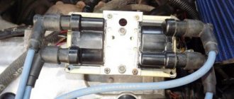
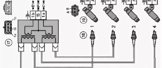
Diagram of the correct connection of wires to the ignition module
If, after checking the wires, you are convinced that they are all tightly connected to the spark plugs, let’s check that the wires themselves are connected correctly. Of course, if no one has climbed into the engine before you, then there is no point in checking. If there was traction and it disappeared, the reason could be both in the coil and in the wires themselves - they could be pierced. But in any case, let's check that the connection is correct. The ignition module shows the numbering of the cylinders to which the wires fit.
- 1 cylinder – central lower outlet
- Cylinder 2 – left output
- Cylinder 3 – top outlet
- 4 cylinder – right output
The diagram is shown for a coil installed on a vehicle.
If after checking no problems are identified, you should consider replacing the coil or wires. It is advisable to change both.
The cost of PVN, depending on the manufacturer, ranges from 300 to 600 rubles per set. The most popular manufacturers:
The cost of an ignition coil is from 1300 to 2500 rubles. Modules from the following companies can be found in stores:
When choosing a module, you should pay attention not only to the manufacturer, but also to the coil itself; it comes in old and new designs. Therefore, it is better to dismantle yours and bring it to the store.
Diagram, procedure for connecting VAZ high-voltage wires.
First, let's decide which of the four cylinders is first?
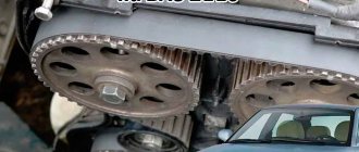
The first cylinder in front-wheel drive VAZs is located closer to the timing belt. If you look at the engine from the front, the first cylinder is the leftmost). And then everything is simple - from left to right - 1, 2, 3, 4.
In rear-wheel drive VAZ Classic and Niva, the first cylinder is located closer to the front bumper of the car.
Connection diagram
The ignition module is part of the space under the hood, it’s easier to find it by the position of the high voltages, they go from the spark plugs straight to it.
Ignition coil diagram:
VAZ 2114 ignition coil diagram
This diagram is good to follow when you have to replace the ignition coil of a VAZ 2114. In principle, everything is transparent: from contacts with the controller (ECU) to high-voltage wires. The name of the circuit is often common under the name ignition coil pinout: the pinout is a visual representation of the functionality of the device's contacts, which are numbered according to their purpose.
It can be connected in two different ways: when the ignition system coil is removed and when it is directly in its place in the car engine.
If you are holding the module in front of you:
- Let us recall the diagram: the first and fourth contacts are on one winding, the second and third – on the other (they are numbered in the diagram!)
- Then, the lower explosive contact (left) goes to the first cylinder
- On the second - upper explosive contact (left)
- The third cylinder goes to the upper explosive contact (right)
- On the fourth – lower explosive contact (right)
If the module is plugged into the engine, then pinouting the explosive contacts will be more difficult, because the device stands at an angle (as if in a diamond):
- We throw the central lower contact onto the first cylinder
- On the second - left contact
- We put the upper contact on the third cylinder
- On the fourth - right contact
Of course, the first installation option is more convenient, especially since the explosive wires require increased care in the nature of the connection (mixed up and won’t start, in the worst case, the entire engine system is ruined). Speaking to the point, it is clear that the connection diagram for the VAZ 2114 ignition module is not complicated.
By the way, buying an ignition coil is not a cheap pleasure; the price of an ignition module for a VAZ 2114 ranges from seven hundred to a thousand rubles, depending on the location of your city on the map of our country (for more information about how much an ignition module for a VAZ 2114 costs, you can find out by calling a disassembly service or a spare parts store, the running part is almost always in stock).
General tips for connecting high-voltage wires.
Checking high-voltage wires. To check the wires, you will need a multimeter tester. Check the resistance of the wires - it should be no more than 20 KOhms (in practice, the longest wire of cylinder 1 has a resistance of up to 10 KOhms). If the wire resistance is more than 20 Kom, it must be replaced. Carefully inspect the wires for chafing on parts of the motor or other wires. In case of significant abrasion, replace the wire. In case of minor abrasion, it is possible to lay the wire so that it does not rub and fix it in this position.
Laying wires. Do not try to connect the wires in a bundle. Disassemble the wiring harnesses, release the wires from the plastic holders. Connect the high-voltage leads to the corresponding cylinder spark plugs. Lay the wires so that they do not rub against each other, engine parts, or hoses. Avoid sharp bends and tension on the wires. After connecting all the wires, secure them into the bundle with special comb holders included in the delivery kit.
The procedure for connecting I/O wires to a VAZ carburetor (2108, 2109, 21099)
The central wire from the distributor cover always goes to the ignition coil (bobbin).
The outlet of the distributor cover, which faces towards the front of the car, is connected to the first cylinder.
The outlet of the distributor cap, looking down, is connected to the third cylinder.
The outlet of the distributor cap, looking rearward, is connected to the fourth cylinder.
The outlet of the distributor cap, looking up, is connected to the second cylinder.
The procedure for connecting high-voltage wires to a VAZ Classic, Niva with a carburetor and distributor.
Central wire from the ignition coil (bobbin)
1 cylinder - above the vacuum corrector. Next, clockwise, the order is 1-3-4-2.
Injection VAZ produced before 2004 with an old-style ignition module (4-pin low-voltage connector)
Actually, on the module body it is already indicated which cylinder the pins correspond to - but we duplicated them in red in case the module gets completely dirty, and you might not be able to see it in the photo.
Injection VAZ produced after 2004 with a new ignition coil (3-pin low-voltage connector)
As with the old-style ignition modules, the new coils are also marked with pins corresponding to the cylinders. But the connection order is different from the order on the old-style ignition module. Be careful.
Schematic electrical diagrams, connecting devices and pinouts of connectors
Today we will look at the design and diagrams of ignition systems for VAZ cars of all major models. Since carburetor versions of VAZ are practically history, we will dwell in detail on the ignition systems of injection cars. Their ignition system is based on an electronic ignition module. We also recommend that you carefully consider the choice of spark plugs and the quality of high-voltage wires, because the quality of the spark and, accordingly, the operation of the ignition system as a whole will depend on them. The information is intended as a reference guide for self-repairing a car.