Among the most popular cars in the domestic engineering industry, it is worth highlighting the VAZ 2110, or as it is also called “Ten”. This vehicle was produced in 1995 - 2007. The 8 valves of the VAZ 2110 were a kind of replacement for the usual carburetor. The main difference between the models is the method of supplying fuel to the fuel cylinders. In the injection machine, everything happened under pressure.
The VAZ 2110 has 8 valves and a more powerful engine. At the same time, fuel consumption is less. Car repair requires the use of additional equipment and painstaking work. Engine capacity 1.5 – 1.6 liters. How to correctly set the ignition on a VAZ 2110 injector with 8 valves? To do this, you need to know the technology of work and then all the actions will seem simple. This will be discussed further.
How to set the ignition on a VAZ 2110, injector, 8 valves
The VAZ 2110, or as it was popularly called “Ten,” was one of the most common domestic cars on our roads. The vehicle was produced from 1995 to 2007 at the AvtoVAZ plant. VAZ 2110 injector, 8 valves was a kind of replacement for the carburetor. The main difference was the type of fuel supplied to the cylinders: in the injection version it is sprayed under pressure. Having a more powerful engine and consuming less fuel, the VAZ 2110 injector requires more painstaking repairs using additional equipment. The engine capacity of the car varied from 1.5 to 1.6 liters. In this article we will look at one of the nuances in car repair, namely: how to set the ignition on a VAZ 2110? First of all, you need to find out what ignition system is installed in the vehicle:
- non-contact with distributor-distributor: the breaker is rotated several degrees and thus the advance angle is set;
- the non-contact electronic ignition system does not have a distributor , and the advance angle is set by controlling the internal combustion engine (using sensors, for example, a crankshaft position sensor).
VAZ 2110
The advance angle is set with the engine running without the vehicle moving with the crankshaft rotating at 820-900 rpm. The angle value is from 0 +/- 1 to the upper mark. If the angle is set incorrectly, the engine will overheat, power will decrease, fuel consumption will increase, and knocking will occur.
First, you need to use sensors, for example, a crankshaft position sensor (which regulates the flow of fuel), to set information in the control unit.
Adjusting the ignition of a VAZ 2110 injector, 8 valves requires some minor car repair skills:
- Release the timing gear drive from the case.
- The distance between the sensor and the toothed disk on the crankshaft should not exceed 0.5 - 0.7 mm so that the sensor impulse can pass through and sparks can form uninterruptedly.
- The crankshaft pulley should be in place, you can check this using the marks. The mark on the flywheel must coincide with the mark on the gearbox housing, for which it is necessary to turn the crankshaft.
- The mark on the oil pump should align with the boss of the cylinder block.
- Another mark on the camshaft drive wheel should coincide with the timing belt cover.
- When all points are aligned, the pistons of cylinders 1 and 4 will be placed in the upper position. Then the distance between the teeth will coincide with the tide on the cylinder block, the 20th tooth will converge with the crankshaft sensor.
- The sensor gives a signal to the internal combustion engine control system that the piston of cylinder number 1 is in the upper position in a state of compression.
Setting marks in the ignition system on a VAZ 2110
When working with current, you must follow safety precautions: wear rubber gloves and choose tools with rubberized handles.
The ignition installation will be complete if you check the work done. Accurate diagnostics can only be carried out using a computer, but you can evaluate the functioning of the circuits:
- check the contacts (only with the ignition off);
- inside the module you need to find out the voltage at terminals C and B;
- To check the high-voltage wire, you need to place a spark plug in the cap and place it on the cylinder block. When you turn on the internal combustion engine using the starter, a spark should appear. All wires must be checked. The absence of a spark should be a reason to check or replace the ignition system;
- If the engine continues to operate incorrectly, you need to check the power system.
On the VAZ 2110 carburetor it is also necessary to set marks to regulate the ignition system. It should be remembered that early and late ignition worsens the ergonomics of your engine and the power drops. The internal combustion engine is exposed to high temperatures and excessive loads. Detonation is also possible.
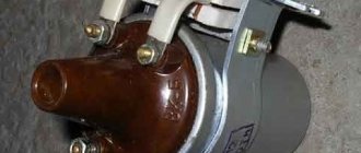
The ignition unit of the VAZ 2110 cannot be repaired; only a complete replacement with a new device is possible!
How does a malfunction of the electronic control unit affect the operation of the injector?
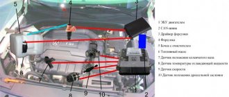
The electronic control unit of the VAZ-2110 car consists of 3 high-precision components:
- ROM – devices for storing data (memory);
- PROM – a device for transmitting dynamic data;
- RAM is the regulating memory of the block.
Advice: the entire complex of presented elements will function only if there is voltage in the circuit. If there is no voltage in the wiring, then it is necessary to eliminate the faults in the fuse box on the VAZ-2110.
Thus, the electronic control unit acts as a kind of microprocessor that is responsible for the operation of the entire fuel supply system. If it breaks down, even an experienced motorist cannot fix it with his own hands. For repairs, contact your nearest car service center and wait for the result. If the unit does not have any malfunctions, the breakdown must be looked for among the elements of the injector and controller.
Tip: in the center of the dashboard on a VAZ-2110 car, a warning light called “CHECK ENGINE” may light up. In this case, the problem definitely does not lie in the control unit, the problem is related to malfunctions in the controller.
So, if you notice that your engine begins to constantly stall while driving and spends more fuel at the same distance as before, refer to the injector diagram for the VAZ-2110. Having a little understanding of each of the elements, you can quickly find the faulty element and replace it.
Setting the ignition timing yourself
In this article you will find useful information about ignition timing and its installation.
First, a brief excursion into the theory: ignition advance is the ignition of the working mixture in the engine cylinder before the piston reaches TDC (top dead center).
When starting to perform this work, it is worth knowing that the ignition timing is checked and set only at idle speed of the engine, and the crankshaft rotation speed should be no less than 820 and no more than 900 rpm. Also, the angle should be between -1 and +1 degrees from top dead center. If the ignition timing is set incorrectly, the engine begins to overheat, does not operate at full capacity, consumes too much fuel and exhibits detonation.
Methods for diagnosing device performance
The simplest method that will help determine the performance of the coil is to replace it with a similar working device. This is possible if there is somewhere to get it. Please note that the module must match the parameters of the device under test. If the engine with a working coil works as before the breakdown, the ignition module is definitely faulty.
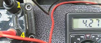
The main testing method involves using a multimeter. It consists in determining the resistance of the secondary windings of the coils built into the ignition module. The method is simple and does not require additional skills. The device does not need to be removed for testing. The check is done with the engine turned off.
This is how you check the resistance of the secondary winding with a multimeter
- High-voltage wires are removed from the module sockets.
- The tester switch is set to the 20 kOhm position.
- The multimeter rods are placed in turn in the recesses of the corresponding contact pairs (1 and 4, 2 and 3).
- With an intact secondary winding, the performance in both cases is the same. Normally, the resistance should be about 5.4 kOhm (in some models the indicators differ, which needs to be clarified). If the resistance is much greater, then there is a winding break. The resistance is much lower - a breakdown. The coil is faulty and cannot be repaired.
Video: How to check the secondary winding with a multimeter
Setting the ignition timing, procedure:
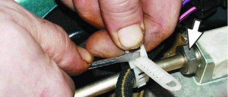
1. First, you will need to disconnect the vacuum hose from the vacuum corrector.
2. Connect the “+” clamp of the strobe to the “+” terminal of the battery. This way you can check the ignition timing.
4. Next, you need to remove the tip of the high-voltage wire from the socket of the first cylinder of the distributor cap and insert the strobe sensor into the vacated socket. Connect the high-voltage wire from the first cylinder to the sensor.
5. Remove the rubber plug from the clutch crater hatch.
6. Start the engine, direct a flashing stream of strobe light into the clutch crater hatch.
7. The mark on the flywheel should visually appear motionless in the flashing light. When the ignition timing is set correctly, the mark on the flywheel will be located between the previous and average pressure of the scale. If the location does not correspond to what is written above, the ignition timing should be adjusted.
8. Loosen the three nuts that secure the distributor to set the ignition timing.
9. The final point in our work is to increase the ignition timing. To do this, turn the sensor housing clockwise so that the “+” mark located on the flange of the distributor housing is aligned with the protrusion on the auxiliary drive housing. One division should be equal to eight degrees of crankshaft rotation. If it is necessary to reduce the angle, it is necessary to turn the distributor body in the opposite direction, that is, counterclockwise.
Replacement
- hex key 5;
- spanners or sockets for 15, 17;
- tension roller wrench;
- large flathead screwdriver.
1.We install the machine on a level area. Raise the hood, turn off the power to the on-board circuit by removing the ground terminal on the battery.
2. Unscrew all six bolts securing the timing case to the left of the cylinder head.
3.Disconnect the contacts on the crankshaft sensor.
4. We check the marks on the gears of both camshafts with the marks on the rear cover of the casing (triangular notches).
5. We also check that the mark on the flywheel crown matches. To do this, use a screwdriver to pry off the rubber plug located on the clutch housing under the thermostat. Under it there is a flywheel gear, on which the mark is located. It should coincide with the cut on the left side of the crankcase.
6. Move on to the crankshaft pulley mark. To do this, you need to loosen the tension on the generator belt by unscrewing the tensioner nut.
7. Having removed the belt from the pulley, we fix the current position of the flywheel by inserting a screwdriver between its crown and the crankcase.
8. Place the 17 key on the generator pulley bolt, unscrew it and remove it. Behind it there is a crankshaft gear with a mark, which should coincide in this position with the mark on the oil pump cover.
9. If any pairs of marks do not match, you need to turn off the gear, screw in the bolt securing the generator pulley, and, without removing the key from it, gradually turn the crankshaft until all the marks match.
10.When the marks are in place, remove the tension roller with a 15mm wrench, then the support roller, and remove the timing belt.
10. We install new rollers, install a new belt, starting with the crankshaft pulley.
11.Tighten the belt by rotating the tension roller clockwise using a special wrench (or fixing it with curved pliers) until the tension is optimal. You can check the degree of tension without the help of tools. It is enough to grasp the belt in the area between the crankshaft pulley and the camshaft pulleys and rotate it horizontally. The optimal tension will be at which you can turn it with your fingers no more than 90 degrees.
12. Installation is carried out in reverse order.
13.Pull out the screwdriver from the crankcase hole.
Injector types
The injector controls fuel injection and can also control the ignition. On all new injection machines, the ignition is set by a computer and regulated by filling in different firmware. But this was not always the case, and on older cars, the same Japanese from the 90s, the computer regulates only fuel injection, and the ignition timing is set using a distributor and is set in the same way as on old Lada models, and depending on the speed The ignition timing is adjusted using a more complex vacuum system than on carburetor Zhigulis. Sometimes, one tube breaks, and during operating mode the traction may disappear; you will have to look for and correct this defect.
But let’s return to more modern ignition systems that are controlled using a computer, especially since these were the ones that were originally installed on the injection VAZ.
How to evaluate the work already done
Accurate diagnosis is carried out using a computer. However, it is also possible to independently assess how correctly the circuits are functioning.
- With the ignition off, check the contacts.
- Find out the voltage inside the module at terminals C and B.
- Check the high voltage wire. To do this, you need to take a candle and place it in the cap. In this case, it should be attached to the cylinder block. If the internal combustion engine is turned on using the starter, a spark will appear. The check is done for all wires. If a spark does not appear, then you need to check or even replace the entire ignition system.
- If the engine continues to operate incorrectly, the power system will need to be checked.
For the carburetor model VAZ 2110, marks are also set in order to regulate the ignition system.
If the ignition of the VAZ 2110 8-valve injector occurs early or, conversely, late, then the ergonomics of the entire engine deteriorates. Power also decreases. The engine is exposed to high temperatures and excessive loads. Among other things, detonation may occur. All this can lead to the VAZ 2110 losing ignition.
Ignition system sensors and marks
For the ignition system to operate correctly, the computer needs to read the correct information from the sensors. Subsequently, this information will be processed in accordance with the fuel maps hardwired into the injector.
The main signal comes from the crankshaft sensor. This sensor shows what position the crankshaft is in at a given time and, based on it, calculates at what moment it is necessary to inject fuel, and at what moment this same fuel should be ignited, depending on the engine speed, which is also determined by this sensor.
1 – crankshaft drive disc; 2 – crankshaft position sensor; 3 – angle of rotation of the crankshaft; 4 – output signal of the crankshaft position sensor
And this is what a typical signal received by a computer from the crankshaft sensor looks like. Pay attention to 270° - this is like the zero point, showing the computer that the engine has completed a revolution and a new cycle begins. This is achieved due to the absence of a tooth on the crankshaft drive sprocket.
About timing marks and their displacement — Lada 2111, 1.6 l., 2005 on DRIVE2
I have been looking for information on timing phases on a 124 internal combustion engine for a long time and came across this material quite by accident. In general terms, I understand what is being said here. But it would not be bad if someone thoroughly chewed on what exactly a change in one direction or another means in pulsations, the angle of inclination of the first tip, the transition through zero, and the value of the maximum vacuum rarefaction.
From my own experience, I can say that shifting the intake 1 tooth to the right adds elasticity. As well as the displacement of the intake together with the exhaust to the right. And shifting the exhaust to the left gives a noticeable jerk-kick (acceleration) somewhere around 3500 rpm.
Timing PHASES on VAZ 2112. The belt was specially rearranged by tooth, back and forth. Engine 21124 (1.6 16kl.) gears:
• ХХ = 840 rpm (engine is warm, measurement after turning off the fan, t = 97 degrees) • difference between DR and DPKV is 0.32 degrees • SOP for DR 14 degrees (real 14 degrees) Note: 1) the difference between DR and DPKV is calculated as follows: First, auto-adjustment is done according to DPKV, then a marker (1 or 2) is placed at the beginning of the ruler (i.e., the value of the marker displayed on the ruler will be 0). Next, auto-adjustment is done according to the DR and the value of the marker (on the ruler) set earlier at the beginning of the ruler is looked at. The displayed value will be considered the difference. 2) the difference between DPKV and DR is calculated as in point 1 only in reverse. First, auto-adjustment is done according to the DR, then according to the DPKV 3) Real UOZ - UOZ according to the scanner 4) As a result of all the experiments, the ECU did not produce a DF (phase sensor) error
Issue 0 tooth is normal; Intake 1 tooth back
Issue 0 tooth is normal; Intake 1 tooth back
Signs: • ХХ = 840 rpm (t = 92 degrees) • The angle of inclination of the 1st tip has increased, it has become more gentle • The pulsations have become smaller • The value of the maximum vacuum and vacuum has become smaller • Extra transitions through 0 have appeared a) Automatic adjustment according to DR • the difference between DR and DPKV is -8.44 degrees • SOP is 25 degrees (real 15 degrees) • the closing degrees of the exhaust valves have shifted slightly to the right • the overlap phase has shifted slightly to the right. b) Automatic adjustment according to DPKV • difference between DPKV and DR is +8.27 degrees • SOP 16 degrees (real 15 degrees) • Exhaust valves close late and intake valves open late • overlap phase has shifted to the right
Issue 0 tooth is normal; Intake 1 tooth forward
Issue 0 tooth is normal; Intake 1 tooth forward
• ХХ = 850 rpm (t = 92 degrees) • The angle of inclination of the 1st tip has decreased, it has become steeper • The pulsations have become larger • The value of the maximum vacuum and vacuum has become significantly greater • Extra transitions through 0 have appeared a) Automatic adjustment according to DR • the difference between DR and DPKV is +15 degrees • OZ 3 degrees (actual 15 degrees), jumped inside the DR oscillogram b) Auto-adjustment based on DPKV • difference between DPKV and DR is -15 degrees • LOZ 16 degrees (real 15 degrees), jumped inside the oscillogram DR • Exhaust valves close early and intake valves open early • overlap phase has shifted to the left Exhaust 1 tooth forward; Intake 0 tooth is normal • ХХ = 840 rpm (t = 92 degrees) • The angle of inclination of the 1st tip has practically not changed • The pulsations have become less • The value of the maximum vacuum and vacuum has become slightly less a) Automatic adjustment according to DR • the difference between DR and DPKV at +3 degrees • SOP for DPKV 12 degrees (real 15 degrees) b) Automatic adjustment according to DPKV • difference between DPKV and DR at -3.47 degrees • SOP according to DPKV 15 degrees (real 15 degrees) • Exhaust valves close a little early and a little early intake valves open • The overlap phase has shifted to the left
Release 1 tooth forward; Intake 0 tooth normal
Release 1 tooth forward; Intake 0 tooth normal
Ignition control
Electronic ignition control
How to set the ignition angle? On systems with electronic ignition control systems, this can be done using computer diagnostics that connect to the Electronic Control Unit (ECU) or the “brains” of the car. And there you can see how the engine operates in real time - what signals are received from the sensors, what engine speed, fuel consumption, injection timing, ignition timing and other input and output data.
ECU (brains) VAZ
The electronic engine control system detects failures associated with wire breaks, short circuits to each other or to ground. With poor contact quality in the connectors. And also with a malfunction of the sensors themselves. However, there are malfunctions in the power and ignition systems that have external signs that are noticed by the driver, but no fault codes are recorded in the memory of the electronic unit. Main symptoms of malfunctions:.
The electronic engine control system detects failures associated with wire breaks, short circuits to each other or to ground.
How the device works
Instead, an ignition module is used, consisting of high-energy control electronics and two coils. The advantage of the new system is that it does not require regular maintenance and maintenance, since there are no moving elements. Also, no special adjustment of the system is required. The reason lies in the presence of a controller. is the one responsible for setting up and adjusting.
How to check the ignition module?
- First of all, we carefully inspect the module body. There should be no chips, burns or cracks on its surface. A module with a damaged casing is replaced without any hassle.
- If the spark is unstable only on cylinders 1-4 or 2-3, one of the module coils is probably damaged. In any case, we will conduct a comprehensive check of the device. For this we will need a regular multimeter.
Dual-circuit ignition on the VAZ 2110
The operation of the system is based on the idle spark technique. The essence of dual-circuit ignition on the VAZ 2110 is as follows:
- Cylinders, as you know, work in pairs - the first with the fourth, the third with the second, etc.;
- The spark fires simultaneously in two cylinders;
- The working spark ignites in the cylinder, where the fuel-air mixture is compressed;
- An idle spark ignites in the cylinder on the exhaust stroke;
- Since the current in the coil windings is constant, it turns out that in the first spark plug the electrons move from the central electrode to the side electrode, and in the second spark plug from the side to the central one.
In the second case, the key size is reduced to 16 millimeters. The distance between the electrodes of the spark plugs is approximately 1 millimeter.
We have already noted that the controller is responsible for controlling the ignition. For the most efficient control, it reads the following data:
- Coolant temperature;
- Presence of detonation;
- Current crankshaft rotation speed and its position at the moment;
- Engine load (air flow).
A special sensor allows the system to understand what position the crankshaft is in. It is he who transmits the relevant information to the controller. After this, it is calculated how and in what sequence the module coils will operate.
Initially, it seems that the system is incredibly complex. But when using the module, everything becomes much simpler. Repairing or maintaining this system does not require spending a lot of time. The procedure is quite easy and can be done with your own hands.
How to remove the coolant temperature gauge sensor?
Before removing the coolant sensor, remove the air filter, it will interfere with its unscrewing. And first of all, drain the antifreeze (antifreeze). We will merge as follows:
- The engine must be cool.
- You will need spanners for 8, 13, 17.
- Prepare a container for the coolant to drain!
- We remove the engine protection, use a wrench to unscrew the radiator mounts
- We set the heater to maximum, then open the heater tap and the cap of the expansion tank.
- We place the container under the radiator and SLOWLY (if you do it quickly, you will flood the generator) unscrew the drain plug.
- Let him run away for about 10 minutes.
- Let's move on to the engine itself: similarly, we place the container under it and unscrew the plug (under the ignition module) on the cylinder block.
- Let it flow again for 10 minutes.
Before closing all the plugs, wipe the neck of each of the holes!
We remember where the coolant temperature sensor is located on the VAZ 2114, and begin to remove it:
- found it, removed the protective rubber layer;
- we look at the body, look for the markings (on one of its 6-sided parts), remember it, so that later we can put everything in accordance with the system;
- unscrew the meter with the twenty-first key;
- install a new one.
How to change the temperature sensor on a VAZ 2114:
- bought a new one;
- Using the same key number 21, we turn the new one into its rightful place;
- remember the markings;
- add a little heat sealant to the threads just to be sure;
- pour coolant (antifreeze or antifreeze) back into the heating system (radiator) and the engine cylinder block.
If the VAZ 2114 coolant temperature sensor still does not work, then carefully check the following:
- Its quality may be defective (take it to the store and ask for a replacement), therefore, always keep the receipt for any spare parts purchase. parts!
- There may be a coolant leak, or perhaps you have splashed the generator after all.
- You just might not have refilled the antifreeze.
- The sensor is not screwed in tightly enough
We checked everything, but the meter still does not show the temperature of the VAZ 2114 engine. Then you should contact a service center. As with any vehicle, everything in the fourteenth is interconnected. The system may fail for a related reason: for example, when you removed the DTOZH, you decided to remove the ignition module so as not to interfere. The decision is correct, however, removing the module and putting it in its place is also an art.
The second point related to the temperature sensor: coolant level. It may be unstable, it may be that the meter for this level (also a sensor) has failed, and so on. Keep an eye on the antifreeze and save your nerves and your coolant temperature meter.
The service will replace the sensor for you and guarantee a high-quality replacement with proper high-quality assembly of all parts in their places. Naturally, you can buy a coolant temperature sensor on the spot, and the cost of replacement work will be twice the cost of the device.
How much a VAZ 2114 coolant temperature sensor costs should be judged based on geographic location: from 80 to 400 rubles in any store that sells auto parts. The pleasure, in principle, is not expensive, but, given the fact of fairly frequent breakdowns (the car stopped being produced in 2013, breakdowns are a natural process), it is still expensive. Therefore, you should not bother with the service, you need to try to figure out the situation yourself. Moreover, now the Internet is saturated with all sorts of useful links, forums, photographs, diagrams and even videos on replacing one or another auto part.
Despite its importance, DTOZH is a relatively simple sensor; its task is to monitor the condition of the coolant (coolant) in the cylinder block jacket. The temperature sensor promptly reports changes in coolant temperature, after which it transmits this information to the electronic control unit (ECU).
DTOZH is often confused with DTUOZH (coolant temperature gauge sensor)
The difference is that the second displays information on the instrument panel in order to keep the motorist informed about what is happening in the engine, essentially about the coolant temperature. While the DTOZH works with the ECU, which, after receiving information about the high coolant temperature, turns on the fan.
DTOZH is often confused with DTUOZH (coolant temperature gauge sensor). The difference is that the second displays information on the instrument panel in order to keep the motorist informed about what is happening in the engine, essentially about the coolant temperature. While the DTOZH works with the ECU, which, after receiving information about the high coolant temperature, turns on the fan.
Operation of the contactless ignition system
- By turning the ignition key, current from the battery is supplied to the mounting block.
- From it, low voltage current passes to the coils, starter and other electrically dependent devices of the system.
- The starter begins to turn the engine. At the same time, the transistor switch receives a signal from the pulse sensor.
- The commutator interrupts the current on the primary winding of the coil, which allows you to create a high voltage current on the secondary winding.
- The resulting current goes to the central terminal of the coil and enters the distributor.
- Depending on the position of the crankshaft, current is transmitted through high voltage wires to the corresponding spark plug.
- The current produces a spark charge that ignites the fuel-air mixture.
Diagnostic procedure
The diagnostic procedure can be as follows:
- Disconnect the connector with signal wires from the module.
- Turn on the ignition and check the voltage at terminal 15 (central) of the control wire block. The rated voltage is 12 V. A drop or absence of voltage when the battery is charged indicates that the engine control unit does not supply power to the module. This means the reason lies in the ECU.
- We remove the high-voltage wires, unscrew the module mounting bots and remove it.
- We check the resistance of the primary windings of the coils - put the multimeter in resistance measurement mode and take readings from the rightmost and central terminals, then from the leftmost and central terminals. The nominal resistance of the primary windings is approximately 0.5 Ohm.
We measure the resistance of the secondary windings between terminals 1-4 and 2-3 high-voltage wires. Nominal value: 5.4 kOhm. If the readings do not correspond to the nominal value, the coil is not working correctly.
Check the module for a short circuit. To do this, install one tester probe on the central pin 15, the second on the metal body. The device should show the absence of a short circuit (one or infinity). Otherwise, one of the coils has shorted to the housing.
Starter problems
Many VAZ 2110 owners had a situation where the starter did not turn after inserting and turning the key. They heard characteristic clicks. This indicates that the solenoid relay is not working.
But the fact is that the “ten” does not have a starter relay, that is, an ignition relay as such. Instead, a solenoid relay works. It is supplied with a positive contact from the ignition switch. Mount this relay to the starter. It has a round shape and is approximately half the size of the starter itself.
Selecting a new belt
It is necessary to choose the correct size belt. The length of the product should be 742 mm. An important question for car enthusiasts is which manufacturer is better to choose.
Today, high-quality products are produced by both foreign and domestic suppliers:
- Volzhsky Automobile Plant. The factory Lada belt 21126–1006040 is considered extremely durable and reliable and quite competitive in comparison with imported analogues. And for the price it wins.
- Domestic belts BRT "Balakovo". According to experts, they are not inferior to foreign analogues. According to many VAZ owners, they are superior to them.
- Belts from Bosch. The brand is synonymous with product quality. A real Bosch belt performs its intended life without any problems. But brand counterfeits are quite common. The quality of counterfeit products cannot be compared with either Russian or foreign products.
- Gates 5631 xs. These belts are popular due to their durability. There is virtually no risk of breakage during the service life.
- Lynx 137 fl22. The Japanese belt is relatively inexpensive compared to other imported models. But it is also of lower quality and has a smaller resource.
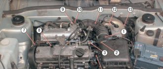
Checking and adjusting the marks on the eight-valve injection valve
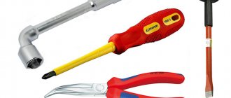
To adjust the ignition you will need the following tools:
- jack;
- wheel wrench;
- key (head) 10;
- key to 13;
- key to 17;
- key to 19;
- large slotted screwdriver;
- flashlight.
It is also advisable to involve an assistant.
- We install the car on a horizontally flat surface. We block the rear wheels.
- Using a wheel wrench, unscrew the bolts securing the right wheel and jack it up. Unscrew the bolts completely and remove the wheel.
- Open the hood, use a 10 mm socket to unscrew the three bolts securing the front protective cover of the timing drive. Let's take it off.
- Using a 13mm wrench, loosen the generator belt tensioner nut and remove the belt.
- Using a 19mm wrench, unscrew the nut securing the generator pulley. To do this, you will need an assistant, whose task is to hold the brake pedal in the cabin when fifth gear is engaged. When all this is done, you will have the opportunity to see all the ignition marks of the VAZ-2110.
- We rotate the front wheel so that the lug on the camshaft gear clearly coincides with the protrusion on the rear timing drive cover. When they are aligned, take a flashlight and look at the position of the mark on the crankshaft pulley. It should point to the test point located on the oil pump cover. If they coincide, without letting go of the flashlight, we move to the engine compartment and compare the position of the marks on the flywheel crown. When the ignition is set correctly, it should also be aligned with the mark on the gearbox housing. In this case, everything is in order with the valve timing. The ignition marks are in their places. If, although the marks on the camshaft and the rear cover coincide, the tide on the crankshaft gear does not coincide with the point on the oil pump cover, it is necessary to make an adjustment.
- Using a 17 key, unscrew the timing belt tensioner pulley. We remove the belt.
- Without touching the timing shaft gears, rotate the wheel until the mark on the crankshaft pulley coincides with the marked point.
- We insert a slotted screwdriver into the inspection window so as to immobilize the flywheel.
- Carefully, so as not to change the settings, put the belt on the camshaft gear and crankshaft pulley. We tighten the tensioner pulley and fix it. Check to see if the marks have gone astray. If necessary, repeat the procedure.
VAZ 2112 timing belt installation
On VAZ 2110, VAZ2112 cars, engines with a 16-valve cylinder head are installed. Of course, an injector with sixteen valves adds agility to our Lada and this is pleasantly pleasing, although there is a fly in the ointment. The timing belt must not be allowed to break due to wear; this leads to damage to the cylinder head. Namely, due to the fact that the camshafts are stationary and at the moment when the piston approaches top dead center, the valves remain open, resulting in the piston hitting the open valves, this leads to the valves bending and in some cases destroying the seats and guide bushings. Repairs are of course expensive.
This can be avoided by installing pistons in the engine that have recesses for the valves, such as in the photo. It is not advisable to do this on purpose, since engines have a significant service life, and there is no point in disassembling a working engine. Therefore, it is easier and cheaper to simply change the timing belt in a timely manner, especially since it does not require extensive experience in locksmith work and deep knowledge in the field of car repair, but just attentiveness and knowledge of some of the nuances when installing the belt itself.
Where to start replacing the belt. First, you need to remove the alternator belt drive pulley. It’s convenient to do this if you remove the right front wheel and the protective cover, if you still have one. Unscrew the pulley mounting bolt. Then remove the timing belt protection covers and the entire mechanism before your eyes. Unscrew the nuts securing the tension rollers; if the belt gets stuck, it is also advisable to change the rollers, and remove them, then remove the belt itself.
We install the crankshaft so that the piston of the first cylinder is at top dead center, this position should correspond to the mark on the crankshaft timing pulley, it should be aligned with the rib on the oil pump housing
In addition, there is a mark on the flywheel; it should be located in the center of the ignition timing scale; it is clearly visible through the inspection window located on the flywheel housing.
Having installed the crankshaft, we install the camshafts so that the valves have a position corresponding to the moment of compression of the fuel in the cylinders when the piston is at top dead center.
For this purpose, there is a mark on the camshaft timing pulley.
must align with the slot on the body of the protective casing
this is typical for both pulleys
Having installed the tension rollers, install the belt as shown in the photo
the hole for fastening the left tension roller is offset relative to the center, due to this the timing belt is tensioned using holes into which a special key is inserted (a screwdriver is also suitable)
After tensioning the belt, turn the crankshaft two turns and align the marks again, this is necessary for self-checking; if this time the marks coincide clearly, then after installing the generator drive pulley and protective covers, the engine can be started.
Features of ignition settings in a carburetor engine
Setting the ignition according to the marks on a carburetor engine is carried out in exactly the same way as on an eight-valve injection engine. The only difference is the need to manually adjust the ignition angle. In a service station environment, this is done using a strobe light and tachometer.
- Raise the hood and use a wrench to loosen the three nuts holding the ignition distributor cap to the body.
- We scroll the lid so that the mark on it coincides with the “zero” mark on the housing scale.
- We start the engine and warm it up to operating temperature.
- Scroll the cap clockwise until the engine begins to produce the maximum number of revolutions. After that, turn it half a division to the left.
- We get behind the wheel and accelerate the car to 60-70 km/h in 4th gear. We press the gas pedal sharply down and listen to the engine. If there is a persistent detonation (fingers knocking) - we have too early ignition. We stop and turn the lid a little more counterclockwise. With the ignition angle set correctly, when we press on the gas, detonation should last no more than 2 seconds, after which the engine, having picked up speed, continues to operate normally.
- Having achieved the desired result, tighten the cover nuts.
To check the ignition timing on VAZ 2110, VAZ 2111, VAZ 2112 cars, there is a scale 1 (Fig. 5) in the clutch housing hatch and mark 2 on the flywheel. One scale division corresponds to 1° of crankshaft rotation. When the mark on the flywheel is aligned with the middle (long) division of the scale, the pistons of the first and fourth cylinders are at TDC.
Rice. 5. Marks for setting ignition timing:
1 - scale; 2 - mark on the flywheel
You can check and set the ignition timing using a strobe, proceeding in the following order: connect the “plus” clamp of the strobe to the “plus” terminal of the battery, the “ground” clamp to the “minus” terminal of the battery, and connect the strobe sensor clamp to high voltage wire 1 th cylinder; Start the engine and direct the flashing strobe light into the clutch housing hatch. To adjust the ignition timing, stop the engine, loosen the nuts securing the ignition distributor and turn it to the required angle. To increase the ignition timing angle, the distributor sensor housing should be turned clockwise, and to decrease it, counterclockwise (when viewed from the ignition sensor-distributor cover). Tighten the fastening nuts and check the ignition timing again.