Today we will talk about the pinout of the diagnostic connector.
With the advent of electronic control systems from microprocessors in cars, the need also arose to check the operating parameters of the units themselves and the connecting electrical circuits. For this purpose, equipment was invented, called OBD (On Board Diagnostic), initially it only provided information about the malfunction, without any clarification.
In modern cars, using an OBD connector with a standard pinout of the diagnostic connector, you can connect a special adapter or scanner to the on-board computer and carry out a complete diagnosis on your own for almost any motorist. Since 1996, the second concept of the OBD2 standard has been developed in the USA, which has become mandatory for newly produced cars.
Determine the purpose of OBD2:
- type of diagnostic connector;
- connector pinout for diagnostics;
- electrical communication protocols;
- message format.
The European Union has adopted EOBD, which is based on OBD2. It has been mandatory for all cars since January 2001. OBD-2 supports 5 data exchange protocols.
Knowing the location and standard pinout of the OBD2 connector, you can check the car yourself. Thanks to the widespread implementation of OBD2, when diagnosing a car, you can get an error code that will be the same regardless of the make and model of the car.
The standard code contains the X1234 structure, where each character carries its own meaning:
- X is the only letter symbol that allows you to recognize the faulty system (engine, gearbox, electronic components, etc.);
- 1 - represents the general OBD2 standard code or additional factory codes;
- 2 - clarification of the location of the malfunction (power or ignition system, auxiliary circuits, etc.);
- 34 is the serial number of the error.
The pinout of the OBD2 diagnostic connector has a special power plug from the on-board network, this allows you to use any scanners and adapters without additional electrical circuits. If earlier diagnostic protocols showed only general information about the presence of a problem, now, thanks to the connection of the diagnostic device with the electronic units of the car, more complete information about a specific malfunction can be read.
Each connected diagnostic equipment must comply with one of three international standards:
- CAN;
- SAE J1850;
- ISO 9141-2.
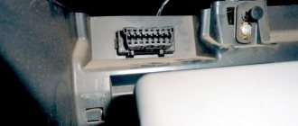
The location of the OBD2 diagnostic connector and pinout for diagnostics can vary greatly from vehicle to vehicle. There is no single standard for location; the car's operating instructions or sleight of hand will help you here.
Below are a few common points for easy reference:
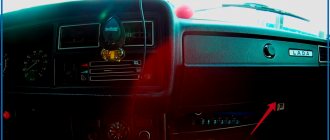
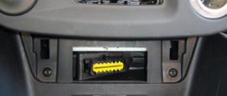
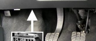
- in the slot in the lower casing of the instrument panel in the area of the driver’s left knee;
- under the ashtray installed in the central part of the instrument panel (some Peugeot models);
- under plastic plugs on the bottom of the instrument panel or on the center console (typical for VAG products);
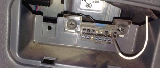
- on the rear wall of the instrument panel behind the glove box body (some Lada models);
- on the center console in the area of the parking brake lever (found on some cars
- in the lower part of the armrest niche (common on French cars);
- under the hood near the engine shield (typical of some Korean and Japanese cars).
Many motorists also sometimes intentionally move the OBD2 pinout connector to another not always standard place; this may be due to electrical wiring repairs or to protect the car from theft.
Description of connector types
In the early 2000s, there were no strict requirements for the outer shape of the connector, and many automakers assigned the device configuration themselves.
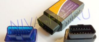
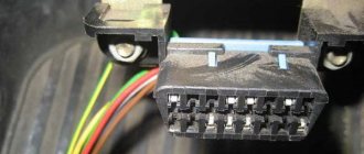
Today, there are two types of OBD 2 connector, designated Type A and Type B. Both plugs have a 16-pin output (two rows of eight pins) and differ only in the central guide grooves. The pins in the block are numbered from left to right, with contacts numbered 1-8 in the top row, and numbers 9 through 16 in the bottom row. The outer part of the housing is made in the shape of a trapezoid with rounded corners, which ensures reliable connection of the diagnostic adapter. The photo below shows both device options.
Connector types – Type A on the left and Type B on the right
Autocom Cable Sets
There are universal kits on sale, for example, a set of Autocom CDP+ Trucks diagnostic cables - used to connect the Autocom CDP+ scanner to trucks with old-style diagnostic connectors.
List of cables included in the kit:
- Diagnostic cable Autocom – Knorr, Wabco Trailer 7 pin
- Diagnostic cable Autocom – MAN 12 pin
- Diagnostic cable Autocom – MAN 37 pin
- Diagnostic cable Autocom – IVECO 30 pin
- Diagnostic cable Autocom – SCANIA 16 pin
- Diagnostic cable Autocom – Mercedes-BENZ 14 pin
- Diagnostic cable Autocom – Renault 12 pin
- Diagnostic cable Autocom – VOLVO 8 pin
With the TRUCKS software package, you are able to perform brand-specific diagnostics for light and heavy commercial vehicles, buses and trailers since 1995. A total of 37 different brands.
Description and features of obd 2
The standard OBD 2 vehicle diagnostic system includes the X1234 code structure.
Each character here has its own meaning:
- X - the element is the only letter and allows you to find out the type of car malfunction. The power unit, transmission, sensors, controllers, electronic modules, etc. may not work correctly.
- 1 - general OBD class code. Depending on the car, it is sometimes an additional manufacturer code.
- 2 - using the symbol, the car owner will be able to clarify the location of the problem. For example, this could be the ignition system, battery power (rechargeable battery), additional power lines, etc.
- 3 and 4 - determine the serial number of the malfunction.
The main feature of the block is the presence of a power output from the vehicle's electrical network, which makes it possible to use scanners that do not have built-in power lines. Initially, diagnostic protocols were used to obtain data about the occurrence of problems in the operation of systems.
Depending on the adapter manufacturer, the device may belong, for example, to the following international classes:
- CAN;
- SAE J1850;
- SAE J1962;
- ISO 9141-2.
The World of Matizov channel spoke in detail about the purpose of diagnostic pads and their use.
How to decipher error codes
Most OBD error codes are unified, that is, a certain error code corresponds to the same decoding.
The general structure of the error code is:
In some cars, the error record has a specific form. It is safer to download error codes on the Internet. But doing this for all errors in most cases will be unnecessary. You can use special programs like AUTODATA 4.45 or similar. In addition to decoding, they indicate possible reasons, albeit succinctly and in English.
It’s easier, more reliable and more informative to enter in a search engine, for example, “error P1504 Opel Verctra 1998 1.9 B”, that is, indicate in abbreviated form all the information about the car and the error code. The search result will be fragmentary information on various forums and other sites. You should not blindly follow all the recommendations at once. But, like the audience's opinions at a famous program, many of them will be plausible. In addition, you can get video and graphic information, sometimes extremely useful.
Where is obd 2 located?
The location of the OBD 2 block is always indicated in the service manual, so it is better to clarify this point in the documentation.
The different positions of the diagnostic plug in a car are due to the fact that vehicle manufacturers do not use a single standard regarding the installation of pads. If the device is classified as J1962, it must be installed within a radius of 18 cm from the steering column. Manufacturers actually do not follow this rule.
The device location may be as follows:
- In a special slot in the lower casing of the instrument cluster. It can be seen in the center console in the driver's left knee area.
- Under the ashtray, which is usually located in the center of the console and instrument cluster. In this place, the connector is often installed by French car manufacturers - Peugeot, Citroen, Renault.
- Under the plastic plugs located on the bottom of the instrument cluster. In this place, the pads are usually installed by the VAG manufacturer - Audi, Volkswagen, etc. cars.
- On the rear of the center console, in the area where the glove compartment housing is installed. This location is typical for some VAZ cars.
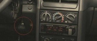
- In the area of the handbrake handle, under the plastic of the center console. This situation is typical for Opel cars.
- At the bottom of the armrest niche.
- In the engine compartment, next to the engine shield. This is where the connector is installed by Korean and Japanese manufacturers.
If the car has a significant mileage, then the installation location may be different. Sometimes, due to electrical faults or damaged circuits, car owners move the connector.
User Ivan Matieshin, using the example of a Lada Granta car, showed where the OBD 2 diagnostic output is installed.
Diagnostics via obd 2
The verification procedure is carried out as follows:
- Depending on the vehicle, the diagnostic process can be carried out with the ignition off or on. This point should be clarified in the service manual. Before starting, the ignition procedure in the car is turned off or on.
- The program is launched on the computer to check.
- The diagnostic equipment is connected to the connector. If this is a scanner, then the block with the wire from it needs to be inserted into the plug. When using a PC, one end of the adapter is installed in the USB output of the computer, and the other is connected to the connector.
- You need to wait until the program detects the block after synchronization. If this does not happen, you should manually go to the control menu and select the option to search for new devices.
- The diagnostic procedure starts on the computer. Depending on the software, the user may have the option to select the desired verification tool. Some programs support separate diagnostics of the engine, transmission unit, electrical network and other components.
- After completing the test procedure, fault codes will appear on the PC screen. These errors must be deciphered in order to accurately determine the type of failure. In accordance with the data received, the vehicle is repaired.
Error code: How to install crack elm327
Determining the obd2 protocol used in the car
The standard regulates 5 protocols, but most often only one is used. The table will help you determine the protocol based on the contacts involved in the connector.
| Protocol | con. 2 | con. 6 | con. 7 | con. 10 | con. 14 | con. 15 |
| ISO 9141-2 | ||||||
| ISO 14230 Keyword Protocol 2000 | ||||||
| ISO 15765-4 CAN (Controller Area Network) | ||||||
| SAE J1850 PWM | ||||||
| SAE J1850 VPW |
In the PWM and VPW protocols there is no 7 (K-Line) pin, in ISO there is no 2 and/or 10 pin.
Connecting diagnostic equipment to the car
Archival article. 2001 – 2003.
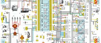
To connect the car to a personal computer, it is necessary to purchase or manufacture a communication interface between the COM port and the K‑LINE diagnostic connector.
The first message on the screen of diagnostic equipment or a computer that causes panic among beginners is usually something like “No connection”, “No controller response” or something similar, but no less intriguing. The motor tester, for example, begins to offer options - from unconnected power to a hardware malfunction of the adapter.
It’s good if the car with the immobilizer was the first to arrive for diagnostics and you are sure that everything is in order with the adapter. The reason for the lack of communication on cars without immo is trivial and is possible only in the domestic auto industry - a break in the diagnostic line running from the diagnostic connector to the ECU.
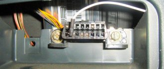
The immobilizer uses K‑Line to communicate with the ECU and is included in the diagnostic line break. If the immobilizer is not installed, then the diagnostic line hangs in the air and there is no connection with the computer. Apparently there was supposed to be a plug in this place, but... To restore communication, you just need to install a jumper between pins 9 - 1 and 18 of the immobilizer connector (or install the immobilizer) as shown in the figure.
Video text
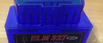
OBD2 adapter, also known as ELM327 (Bluetooth scanner) Elm327 OBD2 is connected to the GM connector ELM 327 | OBD2 | How to connect OBD2 to the GM12(VAG) block ►Link to a verified seller Aliexpress version 1.5 https://ali.pub/2e82kw Running turn signal for cars with AliExpress ► https://ali.pub/3g38g4
Car diagnostics. OBD2 Bluetooth ELM327 V1.5 (this version is the most complete, unlike V2.1 and is suitable for a much larger number of cars with different ECUs)
How to make an adapter from GM-12 to OBD2 with your own hands OBD2 GM adapter with your own hands Bluetooth scanner ELM327 V1.5 OBD2 Mini for computer diagnostics of cars (Aliexpress) In this video we will look at how to connect ELM327 Bluetooth to a VAZ 2110.
►Link to verified seller Aliexpress version 1.5 https://ali.pub/2e82kw
Of course, you can buy a GM12 to OBD2 adapter, but it’s easier to connect an existing adapter using 3 wires.
I took the wires for connecting to the diagnostic connector from an old computer power supply (the terminals on the contacts fit perfectly with the standard 4-pin Molex connector) Connecting the ELM 327 adapter for VAZ diagnostics to the obd1 connector
Diagnostic connector pinout:
If an indicator with an engine symbol lights up on your instrument panel (Check - Check engine), then you need to understand what the error is and what the CHECK ENGINE indicator means. (Check engine malfunction is on), for example, using the free Open Diag or Torque program
What else can the ELM327 adapter do? Using this autoscanner you can reset engine errors check VAZ 21099, 2110, 2111, 2112, 2113, 2114, 2115, Kalina, Priora, Granta (remove error)
obd 2 pinout
Connection diagram of contact elements to the diagnostic block:
- Backup contact. Depending on the manufacturer, any signal can be output to it. He is appointed by the car developer.
- Pin K. Used to send various parameters to the control unit. In many cars it is designated as the J1850 tire.
- A backup contact assigned by the vehicle manufacturer.
- "Ground" of the diagnostic block connected to the vehicle body.
- Ground of the diagnostic adapter signal.
- Contact element for direct connection of the J2284 digital CAN interface.
- Contact for connecting channel K in accordance with the international standard ISO 9141-2.
- Reserve contact element, assigned by the vehicle manufacturer.
- Spare contact.
- Pin required for connection to J1850 class bus.
- The purpose of this contact is determined by the machine manufacturer.
- Appointed by the car developer.
- Reserve pin assigned by the manufacturer.
- Additional contact element for connecting the digital CAN interface J2284.
- Pin for channel L, designed for connection in accordance with ISO 9141-2 standard.
- A positive contact for connecting the car's electrical system voltage, rated for 12 volts.
Error code: What is the OBD II car diagnostic system - Avtoskanery.RU
As an example of a factory pinout of a block, you can use the Hyundai Sonata. In these models, the first pin of the connector is designed to receive signals from the anti-lock braking system control module. Pin number 13 is used to read impulses from the ECU (electronic control unit), as well as airbag controllers.
Pinout types may vary depending on the protocol class:
- If the car uses the ISO9141-2 standard, then this protocol is activated by using pin 7. Pins numbered two and ten are not used and are inactive. To send information, contact elements 4, 5, 7 and 16 are used. Depending on the car, contact 15 can be used for this task.
- If the car implements the SAE J1850 type VPW protocol, then the second, fourth, fifth and sixteenth pins are used in the connector. General Motors vehicles of European and American production are usually equipped with such pads.
- It is possible to use the J1850 protocol in PWM mode. This application involves the additional use of the tenth pin. A similar type of connector is installed on Ford cars. Regardless of the type of output, the seventh pin is not used.
The MotorState channel spoke in detail about the pinout of OBD 2 diagnostic connectors for cars.
Hyundai Sonata ENGINEERING™ 385 entries › Logbook › OBDII pinout where is the truth?
According to the book it’s one thing, but the generally standard pinout is different...
Pinout OBD-2
(On-Board Diagnostic)
is a term that denotes a standard for diagnosing and monitoring the activity of a car engine, some parts of the chassis and other auxiliary devices.
The history of OBD-II began in the middle of the 20th century, when the government of the United States of America unexpectedly discovered that the automobile industry, which they so ardently support, ultimately causes great damage to the environment in general and to humans in particular. Legislative acts appeared, but no one followed them. However, when the energy crisis came, careless producers had to take at least some measures to save themselves and their consumers. It was against this background that the concept began to rapidly develop, suggesting the standardization of such a device as the OBD-II diagnostic connector.
Essentially, OBD-II pinouts are several pieces of standardized rules and requirements that automakers must follow to ensure that all engine management systems meet federal emissions and vehicle performance standards.
Pinout (pin assignment) obd2 connector
| 1 | OEM (manufacturer's protocol). |
| 2 | Bus positive Line. SAE-J1850 PWM, SAE-1850 VPW. |
| 3 | – |
| 4 | Chassis Ground. |
| 5 | Signal Ground. |
| 6 | CAN-High line of high-speed CAN bus (ISO 15765-4, SAE-J2284). |
| 7 | K-Line (ISO 9141-2 and ISO 14230). |
| 8 | – |
| 9 | Line CAN-Low, low-speed CAN Lowspeed bus. |
| 10 | Bus - (Bus negative Line). SAE-J1850 PWM, SAE-1850 VPW. |
| 11 | – |
| 12 | – |
| 13 | – |
| 14 | CAN-Low line of high-speed CAN Highspeed bus (ISO 15765-4, SAE-J2284). |
| 15 | L-Line (ISO 9141-2 and ISO 14230). |
| 16 | Power supply 12V from battery (Battery Power). |
Pins 3, 8, 11, 12, 13 are not defined by the standard.