01/26/2022 10,491 Electronics
Author: Ivan Baranov
The automotive diagnostic connector is a special output that is equipped with all modern cars without exception and the majority of already produced cars. This element is necessary to test the functionality of vehicle components and assemblies and identify malfunctions in their operation. More information about AR can be found in this article.
[Hide]
Diagnostics via OBD 2
The verification procedure is carried out as follows:
- Depending on the vehicle, the diagnostic process can be carried out with the ignition off or on. This point should be clarified in the service manual. Before starting, the ignition procedure in the car is turned off or on.
- The program is launched on the computer to check.
- The diagnostic equipment is connected to the connector. If this is a scanner, then the block with the wire from it needs to be inserted into the plug. When using a PC, one end of the adapter is installed in the USB output of the computer, and the other is connected to the connector.
- You need to wait until the program detects the block after synchronization. If this does not happen, you should manually go to the control menu and select the option to search for new devices.
- The diagnostic procedure starts on the computer. Depending on the software, the user may have the option to select the desired verification tool. Some programs support separate diagnostics of the engine, transmission unit, electrical network and other components.
- After completing the test procedure, fault codes will appear on the PC screen. These errors must be deciphered in order to accurately determine the type of failure. In accordance with the data received, the vehicle is repaired.
Features of the diagnostic connector
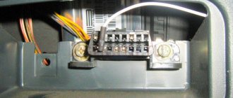
Standard 12-pin connector for diagnostics
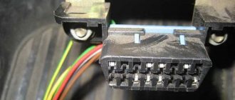
Depending on the year of manufacture of the car, the connector can be 10-pin or 12-pin. To connect to it you will need to make an adapter.
We make wiring
You can also throw a separate wire, but this is “collective farm”.
Diagnostics of modern car models is carried out using a special diagnostic connector. It connects to a computer, which analyzes the current state of the vehicle, determines the malfunction and indicates it. If you have the appropriate equipment, you can look for breakdowns even at home. However, not all VAZ-2112 owners can find the diagnostic connector right away. Today we’ll talk about its location on the classic panel and on the Europanel. In which part of the car should I look for the required socket?
Description of diagnostic connector OBD2 codes
OBD II
What is an OBD diagnostic connector?
It is very important that the presence of a similar connector does not mean 100 percent compatibility with OBD-II. Cars equipped with this system must have a mark on one of the plates in the engine compartment and/or in the accompanying documentation
The most commonly used protocol can be identified by the presence/absence of certain pins on the diagnostic connector. If all contacts are present on this connector, you should refer to the technical documentation for the specific car, which is available on the website.
OBD II diagnostic connector
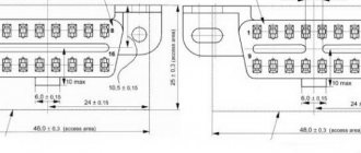
Pin designation
- OEM
- J1850 Bus + Line, SAE
- OEM
- Body grounding
- Signal Ground
- Upper CAN Contact (J-2284)
- K Line ISO 9141-2
- OEM
- OEM
- Bus - Line, Sae J1850 Tire
- OEM
- OEM
- OEM
- Bottom CAN Contact (J-2284)
- L Line ISO 9141-2
- Battery voltage
Diagnostic connector pins for protocols used. Pins 4, 5, 7, 15, 16 - ISO 9141-2. Pins 2, 4, 5, 10, 16 - J1850 PWM. Pins 2, 4, 5, 16 (without 10) - J1850 VPW. ISO 9141-2 protocol is identified by the presence of pin 7 and the absence of pins 2 and/or 10 on the diagnostic connector. If pin 7 is missing, the system uses the SAE J1850 VPW (Variable Pulse Width Modulation) or SAE J1850 PWM (Pulse WidthModulation) protocol. All three data exchange protocols operate via a standard OBD-II J1962connector cable.
DTC Descriptions
The DTC consists of 5 digits. The figure below shows the structure of the DTC code. With this information, you can clear the DTC even if you do not have a description of the DTC.
List of the most common OBDII abbreviations
AFC – Air flow meter ALDL – Diagnostic connector. This is what the diagnostic connector for GM cars used to be called, as well as the connector for connecting a scanner; can also be used as the name of any OBD signal IICAN - ControllerCARB - California Atmospheric Resources BoardCFI - Central Fuel Injection (TBI)CFI - Continuous Fuel InjectionCO - Carbon MonoxideDLC - Diagnostic ConnectorDriving Cycle - The sequence of starting, warming up and driving the vehicle, during this cycle all tests are performed OBD Functions IIDTC – Malfunction CodeECM – Engine Control ModuleEEC – Electronic Engine ControlEEPROM or E2PROM – Programmable Read-Only MemoryEFI – Electronic Fuel InjectionEGR – Exhaust Gas RecirculationEMR – Electronic Ignition Reduction UnitEPA – Environmental Protection CouncilESC – Electronic Ignition ControlEST – Electronic ignition timing adjustmentFuel Trim - mixture composition balancingHC - hydrocarbonHEI - ignitionHO2S - oxygen sensor heatingISO 9141 - international standard for the OBDII connectorJ1850PWM - protocol for the OBD II connector, established according to the SAEJ1850VPW - protocol for the OBD II connector, established according to the SAEJ1962 standard - standard for the diagnostic connector OBD II installed to SAEJ1978 - SAE standard for OBD II scannersJ1979 - SAE standard for diagnostic modesJ2012 - SAE EPA approved standard for emissions test messages
MAF – air flow MAP – absolute pressure in the intake manifold MAT – air temperature in the intake manifold MIL – malfunction indicator lamp. "Check Engine Light" lamp on the instrument panel.NOx - nitrogen oxideO2 - oxygenOBD - diagnosticsOBDII or OBD II - an improved standard for vehicle diagnostics in the USA after 1-1-96Parameters - OBD diagnostic parameters IIPCM - Transmission control unitPCV - CarterProprietary Readings - Parameters on-board computer, which are not required for OBD II diagnostics, but can be used to diagnose malfunctions of various types of vehicles. PTC - Trouble Code RPM - rpm Scan Tool - scanner SES - engine service lamp on the instrument panel SFI - sequential fuel injection Stoichiometric ( Stoy'-kee-o -metric) Ratio – Fuel combustion ratioTPS – Throttle Position SensorVAC – VacuumVCM – Vehicle Central Control ModuleVIN – Vehicle Identification NumberVSS – Speed SensorWOT – Open Throttle
Protocol classification
It was not possible to bring everything to a single exchange protocol, since the system was developed and implemented by many manufacturers at once, and then continuously improved, which continues to this day.
It is also surprising that there are relatively few protocols. In aggregate, they can be counted about nine, although if you notice all the differences, then there are many more. But there are no special problems with compatibility; the scanners include all interfaces, from the first to the most advanced.
A
Class A protocols are the lowest speed, but at the same time simple, based on traditional computer serial interfaces, that is, they do not require significant power in the form of converting microcontrollers. Speed up to 10 kbps. This is what is called K-line.
B
Slightly faster and more complex interface serial protocols, better protected from interference, use various types of digital signal modulation. The speed is approximately 5-10 times higher.
C
So far the most modern protocols, these include the CAN bus, that is, the speed is about 500 kbit/s, the bit depth of code messages has been increased and other algorithms have become more complicated. Good noise immunity of a differential signal from a twisted pair.
ISO9141 protocol
It contains two wires K and L, although exchange is quite possible via a bidirectional K-line, without control via L. Previously, “laces” were widely used - universal K-line adapters. It works quite reliably, but very slowly.
J1850 VPW
Belongs to the group of protocols of the American J1850 standard. Used on GM vehicles. It works five times slower than the completely similar J1850 PWM used by Ford.
Interfaces differ in physical implementation, one- or two-wire lines, modulation in latitude or duty cycle. Described in one standard.
Where is OBD 2 located?
Where is the diagnostic connector on Renault Logan?
The location of the OBD 2 block is always indicated in the service manual, so it is better to clarify this point in the documentation.
The different positions of the diagnostic plug in a car are due to the fact that vehicle manufacturers do not use a single standard regarding the installation of pads. If the device is classified as J1962, it must be installed within a radius of 18 cm from the steering column. Manufacturers actually do not follow this rule.
The device location may be as follows:
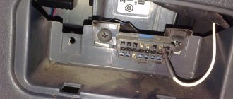
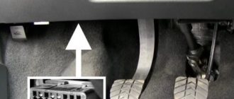
- In a special slot in the lower casing of the instrument cluster. It can be seen in the center console in the driver's left knee area.
- Under the ashtray, which is usually located in the center of the console and instrument cluster. In this place, the connector is often installed by French car manufacturers - Peugeot, Citroen, Renault.
- Under the plastic plugs located on the bottom of the instrument cluster. In this place, the pads are usually installed by the VAG manufacturer - Audi, Volkswagen, etc. cars.
- On the rear of the center console, in the area where the glove compartment housing is installed. This location is typical for some VAZ cars.
- In the area of the handbrake handle, under the plastic of the center console. This situation is typical for Opel cars.
- At the bottom of the armrest niche.
- In the engine compartment, next to the engine shield. This is where the connector is installed by Korean and Japanese manufacturers.
If the car has a significant mileage, then the installation location may be different. Sometimes, due to electrical faults or damaged circuits, car owners move the connector.
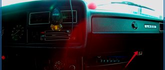
User Ivan Matieshin, using the example of a Lada Granta car, showed where the OBD 2 diagnostic output is installed.
Basic blocking methods
Today, blocking the diagnostic connector is one of the main options for protecting your vehicle from theft. Thanks to the blocking, the car owner will be able to prevent illegal connection to various car systems and avoid possible bypass of the anti-theft system using software. If the engine is blocked, the criminal will not be able to check the blocked motor elements.
There can be several options for blocking a device:
- The first of them is the transfer of the AR itself to another place. So an attacker who tries to steal a car will be faced with the problem of finding an AR that can be installed anywhere. The car owner can move the device to the engine compartment or hide it somewhere in the cabin.
- Re-pinning the DR contacts and making a special adapter for its use. In this case, you only need to reassign a few wires on the device. But in order to use such an DR, you will need a special adapter, where the contacts will also be re-pinned. Otherwise, diagnosing the vehicle will be impossible.
- Complete removal of the AR and installation of a non-standard device in its place. In the future, to carry out diagnostics, you will need a counterpart from such an DR with a block of wires, that is, essentially the same adapter.
- Another method that has recently become widespread is the use of the so-called secret. The secret is a device designed to enhance the functions of the installed immobilizer. As a rule, most modern manufacturers manufacture secret components in such a way that the design of the DR remains the same, and no adapters are needed for its operation. In the event of an attempted theft, the wiring that comes from the DR in the passenger compartment and in the engine compartment is blocked, and a control circuit is placed in the resulting gap. As for control, it all depends on the device manufacturer. For example, an additional DR can be installed, which will be displayed in another location, and sometimes control can be carried out via SMS commands.
Loading …
Diagnostic connector type Priora
Where is the diagnostic connector located in a Lada Granta car?
During the development of “injection” cars, various options for interrogating the ECU (electronic control unit) were developed. At first it was a system for reading codes using a warning lamp. Under special conditions different for different injection systems, the warning lamp began to flash. The master could only write down the rhythm on paper and, checking the table, determine the error.
Subsequently, special diagnostic devices were developed:
- Diagnostic adapters for personal computers.
- Automotive diagnostic scanners.
There are separate articles describing the operation of these devices. But they undoubtedly have one thing in common: a special connector is needed to connect the equipment with the ECU. At first these plugs were made different for each brand of car. There were both round and square. And just paired holes for the dipstick, like on VAG systems. But gradually manufacturers began to think about unification. So, by the early 2000s, the OBD-2 diagnostic connector, now so widespread, appeared.
Attention! Some automakers, mainly producing expensive, exclusive brands of cars, continue to use “their” connectors. But Priora is equipped with OBD-2.
OBD-2 connector design and its contacts
This connecting plug is made of plastic. The connecting part looks like a trapezoid (see photo). In total, it has 16 female contacts. The countdown starts from the top row, from left to right. The top row is considered to be the wide side of the trapezoid. The following sockets are used for the Priora car:
- Ground (ground), slots 4 and 5.
- Constant “+” 12 Volts - 16.
- Diagnostic socket - 7.
Important! Sometimes other sockets are used in the Priora diagnostic connector. Typically these are communication lines with additional ECUs and an L-line for programming
You should not connect to them without special skills in working with software modules.
Typically, the equipment is connected to this connector through a special “plug”. The connector plug is of the same shape, but of the male type. Although those who work with various adapters can make connections directly. This is done on some types of adapters that have a separate probe for the K-line. You just need to remember that the “+” and “-” for the equipment must be taken from the battery of the vehicle being tested. Otherwise the communication signal will be incorrect.
Diagnostic connector location
In addition to the fact that these connectors had different shapes, they were located in different places. On the Priora, it is hidden very cleverly. Without knowing where exactly it is located, finding it is very problematic.
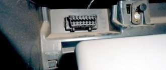
Don't let the fog in. The OBD-2 diagnostic connector on the Priora is located on the inner wall of the glove box on the passenger side. As they call it - the glove compartment. On the part that is adjacent to the “beard”. This is clearly visible in the photo. An experienced specialist, a master diagnostician, will connect with a standard connector by touch without any problems. Simply by opening the box and feeling for the nest behind its wall.
For novice diagnostic specialists, it is better to act according to the instructions. In order. That is, open the glove box completely. It will hang on the side plastic guides. Press these thrust plates a little, and the glove compartment will fold back further.
Carefully pull out the side tabs and release the glove box completely. Then access to the diagnostic input plug will be completely free.
Well, then proceed according to the instructions for connecting the available equipment.
Useful video about the location of the diagnostic connector on the Priora:
- Updating the Navitel application on Android
- Updating Navitel maps on Prestigio navigators
- Installing Navitel on Android
- Navitel maps update for Explay navigator
A detailed description and diagrams of the most common diagnostic connectors are given below:
Output with pin designation. This type is a 12-pin device in which:
- A is the GND output;
- B - K-Line output, which may not exist;
- M - K-Line;
- G — fuel pump control block;
- N - power from the on-board network, but this contact may not exist.
Installed on all VAZ car models with injection engines manufactured before 2002.
OBD-2 device for VAZThis type of 16-pin device complies with the OBD-2 standard. Data exchange with the control unit is carried out via contact K. All VAZ injection-type engines produced after 2002 are equipped with this device. In this case, the motor standard must comply with Euro3 standards.
OBD-2 output for all Volkswagens and most other modern cars. In this case, the purpose of the contacts is as follows:
- 2 — bus plus;
- 4 - earth;
- 5 - signal grounding;
- 6 — CAN contact high;
- 7 — diagnostic line K;
- 10 — bus minus;
- 14 — CAN contact low;
- 15 - L-contact for testing;
- 16 — power supply from the on-board network.
This diagnostic connector is installed on all Volkswagen vehicles manufactured after 1996 without exception. It was also equipped with some Volts produced between 1994 and 1996. Similarly, many vehicles manufactured after 1996 are equipped with such a diagnostic output, including Honda, Renault, BMW, etc.
- 1 — K-Line contact;
- 2 — power contact from the car battery;
- 3 - grounding or ground;
- elements 4 and 5 are used to read the self-diagnosis code.
Diagnostic connectors for Honda vehicles manufactured before 2001.
OBD for all modern Daewoo cars. The purpose of the contacts in this case is as follows:
- 2 — bus plus;
- 4 - earth;
- 5 - signal grounding;
- 6 — CAN bus;
- 7 — output for checking auto K;
- 10 — bus minus;
- 14 - another CAN bus, low;
- 15 — output for checking car L;
- output for power supply from the on-board network.
Diagnostic connectors for Daewoo vehicles manufactured after 2000.
For each type of diagnostic connector, a motorist can easily find a universal device for diagnosing his car and, if necessary, quickly read, reset, analyze sensors and configure the on-board computer. In the event of a minor malfunction, this will help save time and money on trips to a car service center.
As previously noted, it is sometimes quite difficult to find the diagnostic connector in your car. Here are some tips to make your searches easier for certain not-so-modern brands:
- In the engine compartment. Typically, this arrangement of the diagnostic connector is typical for GAZ cars.
- Under the glove compartment on the front passenger side you can find a diagnostic connector in VAZ retro models up to 2002.
- In more modern VAZs, the diagnostic connector is located under the console on the driver's side.
- In Volkswagens (manufactured before 1996), including LT minibuses, the diagnostic connector can be found under the plastic trim in the feet to the left of the driver.
- In Daewoo cars, the diagnostic connector can be located on both the driver's side and the passenger's side
If you have a more modern car, then you can look for the diagnostic connector under the ashtray and under the center console on the driver's side; today this installation location is most common among manufacturers.
Also, do not forget about another very important function of the diagnostic connector, this is a lock to protect the car from theft. As a rule, it is the connection to the diagnostic connector that allows car thieves to quickly bypass the anti-theft system and escape. When the diagnostic connector is blocked, criminals will not have a chance to check the blocked motor elements.
OBD 2 pinout
Connection diagram of contact elements to the diagnostic block:
- Backup contact. Depending on the manufacturer, any signal can be output to it. He is appointed by the car developer.
- Pin K. Used to send various parameters to the control unit. In many cars it is designated as the J1850 tire.
- A backup contact assigned by the vehicle manufacturer.
- "Ground" of the diagnostic block connected to the vehicle body.
- Ground of the diagnostic adapter signal.
- Contact element for direct connection of the J2284 digital CAN interface.
- Contact for connecting channel K in accordance with the international standard ISO 9141-2.
- Reserve contact element, assigned by the vehicle manufacturer.
- Spare contact.
- Pin required for connection to J1850 class bus.
- The purpose of this contact is determined by the machine manufacturer.
- Appointed by the car developer.
- Reserve pin assigned by the manufacturer.
- Additional contact element for connecting the digital CAN interface J2284.
- Pin for channel L, designed for connection in accordance with ISO 9141-2 standard.
- A positive contact for connecting the car's electrical system voltage, rated for 12 volts.
As an example of a factory pinout of a block, you can use the Hyundai Sonata. In these models, the first pin of the connector is designed to receive signals from the anti-lock braking system control module. Pin number 13 is used to read impulses from the ECU (electronic control unit), as well as airbag controllers.
Pinout types may vary depending on the protocol class:
- If the car uses the ISO9141-2 standard, then this protocol is activated by using pin 7. Pins numbered two and ten are not used and are inactive. To send information, contact elements 4, 5, 7 and 16 are used. Depending on the car, contact 15 can be used for this task.
- If the car implements the SAE J1850 type VPW protocol, then the second, fourth, fifth and sixteenth pins are used in the connector. General Motors vehicles of European and American production are usually equipped with such pads.
- It is possible to use the J1850 protocol in PWM mode. This application involves the additional use of the tenth pin. A similar type of connector is installed on Ford cars. Regardless of the type of output, the seventh pin is not used.
The MotorState channel spoke in detail about the pinout of OBD 2 diagnostic connectors for cars.
Where is the diagnostic connector for the VAZ-2114
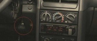
VAZ 2108-2115 with a “European panel”, the diagnostic connector is located in front of the gearbox, directly under the cigarette lighter. The block is closed with a decorative cover. On injection models since 2002, a 12-pin rectangular connector has been used.
The location of the connector is indicated on the diagram in position No. 8 . The following are visual photos of the diagnostic block.
Photo of the block location:
About the ECU and its location is written in the article “Diagnostics of VAZ 2114”. The following shows the pinout of the OBD2 connector and the assignment of contacts of the electronic control units that were installed on the Fourteenth VAZ models.
Connector type No. 1—16-pin OBD-II connector in the shape of a trapezoid:
Brands and years: some models after 2002 with control systems BOSCH MP7.0 Euro-3, BOSCH M7.9.7, January-7.2, January-7.3.
Connector type No. 2 - 12-pin rectangular connector: Make and year: all injection models, except for some models after 2002 that have an OBD-II connector
Connectivity and scanners
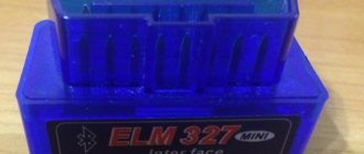
There are different ways to connect to OBD II inputs. The most modern ones include devices equipped with Bluetooth. In this case, gaining access to the on-board system requires a minimum of time and hassle. For Renault Megane there is a convenient OBD II scanner ELM 327 with a Bluetooth adapter. To gain access from a mobile device, use the OBD CHECK Torgue program, available in the official Android Market.
Please note that this scanner does not work with all Renault cars. Limited functionality is available for cars since 2006, but the device does not see all the sensors on earlier models, so to gain access we recommend a standard adapter and a desktop access program
In general, the adapter works with all cars that support the standard since 1996, both diesel and gasoline versions. Please note that diesel and gasoline engines of different modifications may differ greatly.
If you purchased an OBD II ELM 327 adapter, but it does not work, you can do a little restyling.
This can be done in some car services or yourself. Removing parameters from the lower tire was typical before 2004.
This scanner will especially appeal to diesel owners, as it helps monitor engine characteristics in real time. The program displays engine operating parameters and error codes. The device allows you to configure sensors, for example, engine speed, speed, coolant temperature. In general, the device is a serious help for maintenance.
How to choose ELM327
Due to the many clones of different quality, there is a risk of running into a device with reduced functionality that will not work correctly or will not start at all. There are three important things to consider when purchasing.
Connection type
There are several versions of ELM327 with different connection interfaces. The most common are adapters with Bluetooth, Wi-Fi and USB. They differ not only in connectivity, but also in compatibility with smartphones and computers. Otherwise the functions are identical.
- Bluetooth are the cheapest scanners that work only with Android smartphones.
- Wi-Fi - more expensive versions, compatible with both Android and iOS smartphones, as well as computers.
- USB is slightly cheaper than Wi-Fi scanners. They work only with computers, but they are distinguished by reliable communication.
Firmware version
The adapter software is constantly updated. On the original ELM327, the current version is already 2.2. Chinese clones are sold with firmware 1.5 and 2.1. Oddly enough, the newer version is worse.
The chip that came to the Chinese had firmware version 1.5. All clones with this firmware have the original ELM327 software. Later, copies of scanners version 2.1 appeared. The latter is just a modified firmware 1.5, and not for the better - to reduce the cost of production, the Chinese have removed many communication protocols. In addition, there are regular adapters with version 1.5, which are sold under the guise of 2.1.
In fact, three variants of ELM327 clones are currently available for sale:
- ELM327 1.5 - old but original firmware;
- ELM327 2.1 - stripped-down original firmware disguised as newer one;
- ELM327 2.1 - original firmware disguised as new, but without changes.
Obviously, it is worth buying an adapter with the original firmware version 1.5. For example, here is one of the trusted sellers from whom you can buy an inexpensive Bluetooth version of the ELM327.
Car diagnostic connector type
For some cars, especially before 2000 and domestic ones, the diagnostic connector has connectors of other standards. It is not possible to connect a scanner directly to them. For such cases, special adapters are used: on one side they have a compatible connector for a specific car model, and on the other, a standard OBD-II.
On the left is the adapter VAG 2×2 - OBD-II (Volkswagen, Audi until 1997), on the right - GM12 - OBD-II (Daewoo, VAZ) / aliexpress.com
Proprietary pads can have different shapes and number of contacts. Therefore, before purchasing a scanner, check which connector standard is used on your car, and, if necessary, purchase the appropriate adapter.
Description of the Autocom program
List of supported ECUs:
Engine diagnostics using the OBD2 protocol – engine diagnostics using factory protocols – diagnostics of electronic ignition systems – diagnostics of climate control systems – diagnostics of immobilizers – diagnostics of transmission control systems – diagnostics of ABS systems – diagnostics of SRS Airbag systems – diagnostics of the dashboard and reset of service intervals – diagnostics of support systems comfort – diagnostics of body electronics systems
The GENERIC diagnostic program is a standards-based diagnostic program specifically designed to link and standardize fault codes. GENERIC is included for car and truck variants.
With the onboard recorder feature, you can record parameters in real time while the vehicle is moving. While recording, you can, with the press of a button, highlight and remember a specific error for the purpose of studying it later. TCS CDP+ is equipped with built-in memory, eliminating the need for a computer. Memory is not included.
With the Autocom multi-color indicator, you have complete control over the diagnostic process. Different colors and sound prompts will indicate to you which diagnostic stage is currently running. For example, if the indicator switches between blue and green, it communicates with the vehicle's control unit.
When Autocom is connected to a vehicle, the device will check the vehicle's onboard voltage and automatically adjust to the vehicle's 12 or 24 volt voltage level. If the voltage gets too high or too low, Autocom will alert you with both an audible prompt and an indicator light, as well as an alert via the battery icon in the software.
The software has a feature that allows you to read the chassis number from the vehicle you would like to diagnose. This ensures that the model and year are selected automatically. In addition, the engine code for vehicles that are usually available for reading is also automatically selected.
The Intelligent Scanning System (ISS) scans all the systems in the vehicle and displays the fault codes that are stored in each system. This saves time and gives you a quick overview of the current condition of the vehicle as a whole. Once the ISS is completed, you can select a dedicated management system to analyze the results further.
Intelligent System Identification (ISI) detects and automatically selects the type of controller that is installed in the vehicle. This ensures that the diagnostic session is completed correctly with the correct parameters as required.
According to this feature, you will be able to see the adaptations and adjustments that are possible for a particular vehicle without having the vehicle near you. Together, using the texts as a guide, you can plan and be effective in your work, even in difficult situations.
The Autocom car scanner is equipped with a unique multiplexer technology, which allows it to be used on all types of vehicles, regardless of voltage level and communication standards. For those vehicles that do not use a standard 16-pin connector, it is possible to connect special adapter cables.
What is ELM327
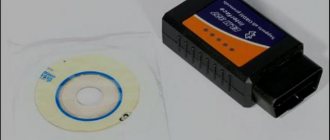
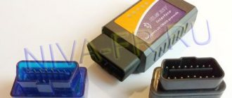
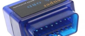
The designation ELM327 is well known to many car owners. This is a scanner or adapter that connects to the car’s on-board computer via the OBD-II connector. A useful device is used to diagnose faults, read performance indicators and reset ECU (electronic control unit) errors.
Scanner ELM327 / aliexpress.com
The scanner got its name from the microcontroller, which is a kind of connecting link between the car’s diagnostic bus and a computer or smartphone. This chip, developed by a Canadian company, fell into the hands of Chinese electronics manufacturers, who jumped at the chance to copy it.
What is OBD-II diagnostics Auto Other
OBD-II connector
Equipping a vehicle with an on-board diagnostic system of the OBD-II standard requires the presence of a special connector designed to connect diagnostic and control equipment to the vehicle. The OBD-II connector is located inside the cabin under the steering wheel and is a block with two rows of 8 contacts. The diagnostic connector is used to power the equipment from the vehicle battery, grounding and information transmission channels.
The presence of a standard connector saves time for car service center specialists, who thereby eliminate the need to have a large number of separate connectors and devices for processing signals coming from each connector.
Access to information and its processing
The OBD-II standard provides for the use of an error codification system. The error code consists of one letter followed by four numbers, indicating malfunctions of various systems and components of the vehicle. Access to information transmitted using the on-board diagnostic system allows you to obtain valuable data necessary for faster and better determination of the technical condition of the vehicle and troubleshooting existing problems.
In accordance with the ISO 15031 standard, the OBD-II data exchange system has various modes for reading, processing and transmitting information. Car manufacturers independently decide which modes to use for a particular car model. Manufacturers also independently determine which diagnostic protocol to use when using the OBD-II system.
There is special equipment for working with vehicle condition data according to the OBD-II standard. The devices differ in functionality and, in general, are an adapter that is connected to the car using the OBD-II connector and to the computer using a standard USB connector. The equipment comes with software that allows you to read and analyze information.
The diagnostic systems installed on modern vehicles include several devices that monitor parameters related to toxicity. The OBD diagnostic system also records failures in the on-board computer's memory, translating them into individual fault codes. The location of the diagnostic connector depends on the vehicle make and specific model.
You will need
Instructions
As an example, consider the location of the diagnostic connector on Opel vehicles. The OBD-II connector, by current standards, must be located within 16 inches of the steering column. The standards require eight locations for placing the diagnostic unit.
Inspect the area in the immediate vicinity of the steering wheel. If your Opel vehicle was manufactured before 1996, it uses a rectangular diagnostic connector with ten pins. The contacts are arranged in two rows in a vertical position and are marked A, B, C, D, E, going from bottom to top in the left row, and in the right - F, G, H, J, K (markings go from top to bottom).
On models manufactured after 1996, look for a diagnostic connector with sixteen pins arranged horizontally in two rows. The device has a trapezoid shape and supports the OBD-II standard.
If you have an Opel manufactured after 2000, look for the diagnostic connector under the front decorative panel (dashboard). In some cases, the device is closed with a separate cover.
On 1996-2000 vehicles, inspect the fuse box in the front panel, as well as the area under the plastic cover near the handbrake. This applies to Opel Corsa, Opel Omega, Opel Astra F.
To gain access to the diagnostic connector in Opel Omega B, Opel Astra cars produced between 1995 and 2000, disconnect the cover of the block where the fuses are located. This block is located in the passenger compartment, to the left of the steering wheel, in the dashboard.
To locate the corresponding diagnostic device in the Opel Zafira 2000-2004 model, first disconnect the cover located under the handbrake, and then remove the plug that protects the connector itself.
Open the ashtray cover located near the gearbox lever of the Opel Vectra C. Pull the ashtray body out. Now access to the desired device is open.
Video on the topic
Where to look for the connector
It is important to know that on different cars the required socket is located in different parts of the car. Moreover, on some AvtoVAZ models it may be in a completely different place compared to another car. Let's look at several VAZ cars as an example:
- on the VAZ-2112, as well as on the 2110, as well as 2111, the socket is located to the right of the driver’s seat, immediately under the column;
- on models 2108, 2109 and 21099, the socket you need is located under the glove compartment, on a special shelf;
- on cars with a europanel it can be found in the center of the console, near the cigarette lighter. A special decorative cover is used to disguise it;
- on Lada Kalina cars, the connector can be found near the gear shift lever. As is the case with cars with a Europanel, it is hidden under a special cover;
- on a Priora you need to look for it right behind the glove compartment, on the wall.
Thus, on the VAZ-2112 the diagnostic connector is located on the right side of the driver’s seat. It is located immediately under the steering column and, in principle, is not so difficult to find. Inspect the bottom of the panel.
All about the international control system obd 2 pinout
Since 1996, there has been a need to check all manufactured vehicles for compliance with OBD standards. This was caused by the requirement to control the environmental situation. A brief description of the control device, location, functions is further in our article.
Brief description of the control device
The OBD-2 pinout designation is used to check compliance with the standard during diagnostics and monitoring of the operation of car engines and units installed on the chassis. The device is made in the form of a diagnostic connector for connecting devices that monitor exhaust gases and the operation of the entire car without interruption. The OBD-2 pinout is a set of requirements that all automakers must meet.
ATTENTION! Tired of paying fines from cameras? A simple and reliable, and most importantly 100% legal way has been found to stop receiving “chain letters”... Read more"
Location of contacts for obd 2 connectors
It is required that the connector be located in the passenger compartment at a distance of at least 18 cm from the steering column. The system is universal for all cars and has a standard digital CAN protocol, allowing data to be taken at any time. You can make detailed identification of various problems in the machine.
When diagnosing imported cars, additional lines K - Line and L - Line are used, as well as digital methods of transmitting indicators - CAN.
The monitoring function is supported by sixteen contacts:
- contact number one - it is installed at the manufacturer;
- the second refers to the J 1850 bus;
- number three is also put by the automaker;
- the fourth - for monitoring the grounding contacts of the car - chassis;
- number five controls the signal line ground network;
- contact number six is responsible for the CAN digital bus;
- number seven – ISO 9141 – 2, K – Line;
- eight and nine are installed by the automaker;
- the tenth controls the CANJ 1850 bus;
- numbers eleven, twelve and thirteen are also installed at the car plant;
- contact number fourteen controls the CANJ 2284 bus;
- fifteen – ISO 9141-2, L – Line;
- The sixteenth controls the battery voltage.
OBD adapters – 2 connectors for diagnostics
Cars of all brands must be equipped with an OBD-2 diagnostic adapter. It is used when diagnosing a car independently or in service centers. Are you looking for real homemade porn with juicy college girls? Yes, this is a cool genre, and thank heavens that we have plenty of such goodness. Follow the link and judge for yourself how cool the homework is, downloaded for free in our categories. For every taste, anal, incest, with mom or granny - all this will perfectly brighten up your evening. Especially with a beer it will go down with a bang, try it and don’t be shy about your wishes. The adapter is convenient for:
- diagnosing all car components;
- analysis of errors and mileage status;
- monitoring engine operation;
- for tension;
- temperature;
- speed;
- condition of panel instruments;
- you can track average and current fuel consumption;
- degree of engine warm-up;
- control the trips.
Connector functions provided by OBD-2 pinout
The main function of the OBD – 2 connector is to provide communication between the scanning device and control units. The pinout provides for connecting the vehicle power supply and grounding for successful operation of the vehicle scanner, without connecting a special power supply. When choosing a scanner, you should find out about its capabilities. The higher its price, the more accurate the verification will be. If it is not possible to purchase an expensive device, you need to choose a scanner made specifically for a given car brand.
The pinout allows the driver to combine his car with the OBD-2 diagnostic block.
If a non-compliance with certain exhaust gas composition requirements is detected, the CheckEngine signal appears, calling you to check the operation of the engine, and the light signal turns on. This is an indicator warning that the amount of harmful gases is exceeding the norm.
With the help of the obd 2 pinout system, vital parameters are monitored, the main one of which is clean air. The presence of the connector makes it possible to monitor the degree of serviceability of the vehicle without qualified, expensive assistance.
How to pay TWICE LESS for GASOLINE
- Gasoline prices are rising every day, and the car's appetite is only increasing.
- You would be happy to cut costs, but is it possible to live without a car these days!?
loading…
How to check the ELM327 scanner
After purchasing the ELM327 adapter, check that it is indeed version 1.5. When ordering from AliExpress, check whether the PIC18F25K80 chip is installed in it and emphasize that you will diagnose the scanner using special software and open a dispute in case of problems.
Visual inspection
Visually identifying a quality adapter is not so easy. The opaque or dark plastic housing makes it impossible to inspect the components. Their miniature size and hard-to-read markings further complicate matters.
PIC18F25K80 chip on the scanner board / aliexpress.com
If you carefully open the case, you can look at the ELM327 boards. Carefully inspect all the parts and look for the processor code PIC18F25K80. Firmware 1.5 requires just such a chip, so its presence will be a certain guarantee of quality.
Application tester
YouTube channel Eugene Barsuk
A special application tests compatibility with diagnostic bus protocols and shows the real version of the scanner. To check, do the following.
- Insert the ELM327 adapter into the car's diagnostic connector and turn on the ignition.
- Open the Bluetooth or Wi-Fi settings on your smartphone and pair with the adapter (password: 0000 or 1234).
- Install the verification application and click the “Connection” button.
- Wait for the scan to finish and check the results.
- Successful work with most car brands is guaranteed if the adapter supports all revisions up to 1.4 or 1.4b inclusive.
OBD adapters 2 connectors for diagnostics
Cars of all brands must be equipped with an OBD-2 diagnostic adapter. It is used when diagnosing a car independently or in service centers. The adapter is convenient for:
- diagnosing all car components;
- analysis of errors and mileage status;
- monitoring engine operation;
- for tension;
- temperature;
- speed;
- condition of panel instruments;
- you can track average and current fuel consumption;
- degree of engine warm-up;
- control the trips.
You can connect laptops, computers, and phones to the adapter. It is suitable for connecting to the OBD-2 system and all programs that are subject to their OBD 2 pinout requirements. The connection is made with a USB cable, Bluetooth or WI – FI. Using the adapter, you can test cars of all kinds of imported and domestic manufacturers.
What does the ELM327 scanner do?
The functionality of the ELM327 is quite extensive. But it largely depends on the support of certain capabilities by the specific version of the adapter, the ECU of the machine itself, as well as the software that is used for diagnostics.
In addition to reading, decoding and clearing diagnostic error codes, the scanner can display in real time engine speed and vehicle speed, the temperature of all fluids, current fuel and air consumption, throttle position, pressure in the fuel system and much more.
In some cars, using the ELM327 adapter, you can unlock and reconfigure automatic locking and folding of mirrors, gas pedal responsiveness, and dashboard data.
Types of connectors
In modern vehicles, two types of diagnostic sockets can be used - classes A or B. Both connectors are equipped with 16-pin outputs, eight contacts in each row. The contact elements are numbered from left to right, respectively, components numbered 1–8 are located at the top, and 9–16 at the bottom. The outer part of the body of the diagnostic block is made in the form of a trapezoid and is characterized by rounded shapes, which makes it possible to connect an adapter.
The main difference between the different types of connectors is the guide grooves located in the center.
Scanners for cars
If you need to diagnose an electronic control unit (ECU), then car scanners will do an excellent job of this. The standard model of the device is not equipped with sensors. Using connecting wires, the scanner is connected directly to the ECU, from where it receives all the necessary information. The absence of such a device at hand can seriously complicate the diagnosis of a modern car, and its presence will make it possible to quickly find faults and eliminate them at an early stage.
A car scanner allows you to:
- activate the equipment;
- change the software “stuffing” of the block;
- open access to passport data;
- view errors and get rid of them;
- change the data display mode on the dashboard;
- and much more.
Some types of car scanners are capable of reading additional data. These include parameters with an error code that were automatically stored in the ECU memory after occurrence. An additional function helps to identify the causes of a malfunction, and not just the fact that it exists.
Among the scanners there are also models that have additional functionality due to the built-in oscilloscope and multimeter sensors. They provide access to a wide range of data, which makes them indispensable for preventive use.
Autocom Cable Sets
There are universal kits on sale, for example, a set of Autocom CDP+ Trucks diagnostic cables - used to connect the Autocom CDP+ scanner to trucks with old-style diagnostic connectors.
List of cables included in the kit:
- Diagnostic cable Autocom – Knorr, Wabco Trailer 7 pin
- Diagnostic cable Autocom – MAN 12 pin
- Diagnostic cable Autocom – MAN 37 pin
- Diagnostic cable Autocom – IVECO 30 pin
- Diagnostic cable Autocom – SCANIA 16 pin
- Diagnostic cable Autocom – Mercedes-BENZ 14 pin
- Diagnostic cable Autocom – Renault 12 pin
- Diagnostic cable Autocom – VOLVO 8 pin
With the TRUCKS software package, you are able to perform brand-specific diagnostics for light and heavy commercial vehicles, buses and trailers since 1995. A total of 37 different brands.
see also
Which scanner is better for diagnostics?
- 43 0 19k
How to check the fuel pressure regulator
- 82 0 56k
Pneumotester
- 16 1 22k
Checking pump injectors: software diagnostics and measurement with a multimeter
- 88 0 38k
Do-it-yourself injector flushing. Types of injector flushing
- 14 0 28k
The design of modern cars allows the use of various types of diagnostic equipment for preventive checks and examination of systems when signs of malfunction occur.
Diagnostic devices can be divided into three separate groups:
- car scanners;
- motor testers and oscilloscopes;
- devices to test a specific system.
Representatives of groups have characteristic differences and have their own ramifications depending on their purpose and general functionality.
Portable auto scanner, motor tester, equipment for diagnosing a specific system (chassis).
Pinout assignment of OBD2 connector pins
| 1 | OEM (manufacturer's protocol). |
| 2 | Bus + (Bus positive Line). SAE-J1850 PWM, SAE-1850 VPW. |
| 3 | – |
| 4 | Chassis Ground. |
| 5 | Signal Ground. |
| 6 | CAN-High line of high-speed CAN bus (ISO 15765-4, SAE-J2284). |
| 7 | K-Line (ISO 9141-2 and ISO 14230). |
| 8 | – |
| 9 | Line CAN-Low, low-speed CAN Lowspeed bus. |
| 10 | Bus – (Bus negative Line). SAE-J1850 PWM, SAE-1850 VPW. |
| 11 | – |
| 12 | – |
| 13 | – |
| 14 | CAN-Low line of high-speed CAN Highspeed bus (ISO 15765-4, SAE-J2284). |
| 15 | L-Line (ISO 9141-2 and ISO 14230). |
| 16 | Power supply +12V from the battery (Battery Power). |
Pins 3, 8, 11, 12, 13 are not defined by the standard.
Types of car scanners
Devices for reading information can be in the form of a stand-alone device with its own software and technical equipment or a special complex for a PC. The complex includes not only software for the OS, but also a set of adapters.
There are 2 types of car scanners:
- multi-brand;
- dealer
Multi-brand auto scanner LAUNCH
Dealer scanner VAG vas
Multi-brand scanners are characterized by the ability to work with many vehicles . Their advantage is the installation of several protocols for data exchange with the ECU. A set of adapter cables is supplied with such devices. It allows you to work with different configurations of diagnostic connectors. Unfortunately, most multi-brand scanners have limited functionality.
As for the dealer type scanners , they are designed to work with one or more car models . They support a specific protocol, which means they can only work with “related” brands. Among the features of dealership car scanners, it is worth highlighting: a set of various functions and guided diagnostics. It allows you to analyze ECU data and uses a special algorithm to identify possible causes of the error and determine how to eliminate them.
Detailed descriptions and diagrams of the most common diagnostic connectors
Output with pin designation. This type is a 12-pin device in which:
- A is the GND output;
- B - K-Line output, which may not exist;
- M - K-Line;
- G — fuel pump control block;
- N - power from the on-board network, but this contact may not exist.
Installed on all VAZ car models with injection engines manufactured before 2002.
OBD-2 device for VAZ. This type of 16-pin device complies with the OBD-2 standard. Data exchange with the control unit is carried out via contact K. All VAZ injection-type engines produced after 2002 are equipped with this device. In this case, the motor standard must comply with Euro 3 standards.
OBD-2 output for all Volkswagens and most other modern cars. In this case, the purpose of the contacts is as follows:
- 2 — bus plus;
- 4 - earth;
- 5 - signal grounding;
- 6 — CAN contact high;
- 7 — diagnostic line K;
- 10 — bus minus;
- 14 — CAN contact low;
- 15 - L-contact for testing;
- 16 — power supply from the on-board network.
This diagnostic connector is installed on all Volkswagen vehicles manufactured after 1996 without exception. It was also equipped with some Volts produced between 1994 and 1996. Similarly, many vehicles manufactured after 1996 are equipped with such a diagnostic output, including Honda, Renault, BMW, etc.
- 1 — K-Line contact;
- 2 — power contact from the car battery;
- 3 - grounding or ground;
- elements 4 and 5 are used to read the self-diagnosis code.
Diagnostic connectors for Honda vehicles manufactured before 2001
OBD for all modern Daewoo cars. The purpose of the contacts in this case is as follows:
- 2 — bus plus;
- 4 - earth;
- 5 - signal grounding;
- 6 — CAN bus;
- 7 — output for checking auto K;
- 10 — bus minus;
- 14 - another CAN bus, low;
- 15 — output for checking car L;
- output for power supply from the on-board network.
Diagnostic connectors for Daewoo vehicles manufactured after 2000
For each type of diagnostic connector, a motorist can easily find a universal device for diagnosing his car and, if necessary, quickly read, reset, analyze sensors and configure the on-board computer. In the event of a minor malfunction, this will help save time and money on trips to a car service center.
As previously noted, it is sometimes quite difficult to find the diagnostic connector in your car. Here are some tips to make your searches easier for certain not-so-modern brands:
- In the engine compartment. Typically, this arrangement of the diagnostic connector is typical for GAZ cars.
- Under the glove compartment on the front passenger side you can find a diagnostic connector in VAZ retro models up to 2002.
- In more modern VAZs, the diagnostic connector is located under the console on the driver's side.
- In Volkswagens (manufactured before 1996), including LT minibuses, the diagnostic connector can be found under the plastic trim in the feet to the left of the driver.
- In Daewoo cars, the diagnostic connector can be located on both the driver's side and the passenger's side
If you have a more modern car, then you can look for the diagnostic connector under the ashtray and under the center console on the driver's side; today this installation location is most common among manufacturers.
Also, do not forget about another very important function of the diagnostic connector, this is a lock to protect the car from theft. As a rule, it is the connection to the diagnostic connector that allows car thieves to quickly bypass the anti-theft system and escape. When the diagnostic connector is blocked, criminals will not have a chance to check the blocked motor elements.
Car diagnostic connector OBD2: versions and protocolsComputer76
Do-it-yourself car diagnostics: OBD port to help.
Almost none of the visitors to this site are professional repair engineers of... or anything. We have different professions, we can do the usual things around the house: replace a lamp, hammer a nail... lay tiles, install windows... However, many have one item that is both an object of adoration and a separate element of the family budget. We use it to move our organisms from point A to points B, C and further in alphabetical order.
It’s unpleasant when the moment comes when our means of transportation, turning into a “luxury,” refuses to do this. Well, the tire is punctured, there is antifreeze on the road - everything is clear here. What if it doesn’t start or works as it pleases? We dedicate a section to cars. And you can deal with many of your car’s problems on your own. Now, however, there are many bus stations that read errors from the on-board computer. And it's free. But there are already offers on the market with which you can carry out computer diagnostics of a car yourself.
Looking for an OBD2 port
First, you should find the OBD2 port itself. Below the steering column, next to the fuse box or in the middle of the dashboard - and always covered with a lid from casual view. You'll have to squat down, but when you see it, you won't confuse it with anything:
REFERENCE
Domestic cars began to have an OBD2 diagnostic connector since January 1, 2012.
By the way, you can (theoretically) find out about its existence and exact location right now. We go to the CarMD website, enter the model, make and year of the car (not all are available, there are no Russian ones, and foreign cars are not represented by all models - I chose the appropriate one):
and in a moment you will be shown where to look:
I remember there was even an illustrated application for Android OBD Port Lookup, but the Google Store is currently giving an error for this name. But finding a connector isn't the hardest part.
OBD2 Errors: Learn to Read and Understand
Did you find it? Take a closer look at it. I know two types of OBD2 connectors: type A and type B. They are easily distinguishable:
How to determine the protocol version? Look at the connector pins:
contacts involved (from left to right, from top to bottom) 2 6 7 10 14 15
Here is a table that will help you understand the protocol version:
| to 2 | by 6 | by 7 | k10 | by 14 | by 15 | Standard |
| There is | There is | J1850 PWM | ||||
| There is | J1850 VPW | |||||
| There is | There is* | ISO9141/14230 | ||||
| There is | There is | ISO15765 (CAN) |
* Pin 15 is also called L-line. Its existence is optional in new versions of cars using the ISO9141-2 or ISO14230-4 protocols.
Taking a closer look at the contacts, you will understand that the table is incomplete. Yes, in addition to pins 2, 7, 10, and 15, the connector must have pins 4 (chassis ground), 5 (circuit ground), and 16 (battery plus). Thus, the protocol type is determined by the presence of contacts:
| J1850 PWM | the connector has pins 2, 4, 5, 10 and 16 |
| J1850 VPW | the connector has pins 2, 4, 5 and 16 (without 10) |
| ISO9141/14230 | the connector has pins 4, 5, 7 and 16. Pin 15 is present or not |
| ISO15765CAN | the connector has pins 4, 5, 6, 14 and 16 |
One way to find out which version of OBD your vehicle's on-board computer supports is to look for the Vehicle information label. Under the hood it can (or cannot) be seen in several places at once. It is made in the form of a plate on a metal or paper base, and, among other things, necessarily contains the inscription OBD XX certified. This is your version.
Good luck
Similar
computer76.ru
Motor testers and their functions
The motor tester is used to obtain data on the operation of the engine electrical equipment , and also has the functions of an oscilloscope. The main distinguishing feature from a car scanner is the method of obtaining information. The device is equipped with its own sensors, which allows it to bypass the ECU and receive data directly.
An oscilloscope is a device that reads data from sensors , which is capable of displaying it in graphical or numerical form and then analyzing it. For comparison, standard indicators available for each model are used. Sometimes an oscilloscope is used separately from a motor tester.
Motor tester functions:
- Tester mode
- diagnostics of engine systems and comparative analysis with nominal values (for example, starting current testing).
| There are several types of connectors for diagnosing VAZ cars, including EURO 3 (4). To connect a car to a computer or laptop, you need to purchase or manufacture a communication interface between the COM port and the K-LINE diagnostic connector. It looks something like the picture below. |
- Oscilloscope mode analysis of the operation of ECU sensors;
- reading the parameters of control signals that go from the electronic control unit to various actuators;
- collection and verification of data on the operation of ignition system circuits;
- etc.
- diagnostics of parameters not related to electronics (for example, obtaining data on oil and fuel pressure).
