The design of the VAZ 2107 car provides for the presence of a specialized connector, the main purpose of which is to study the technical condition of the vehicle. Today, such devices are manufactured according to the same OBD2 standard. Moreover, the diagnostic connector on the VAZ 2107 of the OBD2 type has been installed since 1995, and before that, cars were equipped with OBD1 type devices. Let's take a closer look at what this device is and what its purpose is in the design of the seven.
Where is the diagnostic connector located?
The type of device in question, which is also called a diagnostic block, in the design of the 7 and other cars serves to check the condition of the vehicle for errors and malfunctions. After such manipulation, you can decide on the need to repair or replace parts and mechanisms.
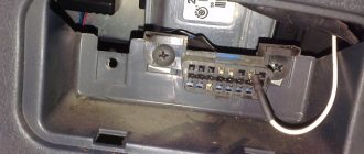
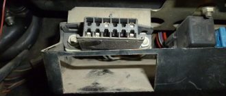
Structurally, the connector is a contact connection with a large number of pins. An autonomous source (computer) is connected to this connection, and a test event is carried out using special programs. On the seven, the diagnostic connector is located in the passenger compartment on the passenger side under the glove compartment. By the way, on many car models of domestic and foreign production, the connector is also located in this place.
To connect the computer to the car via the connection, you do not need to disassemble, remove or unscrew anything. The check can be carried out while inside the car, since the essence of this process is to identify errors in the operation of the engine.
Knowing where the connecting element is located, figuring out the connection to the computer will not be difficult. To connect the computer to the car via the OBD2 connector, you will need a special cable with the appropriate plugs (connectors). However, there is an easier way to avoid buying a cable. To do this, you need to connect two contacts in the block so that the ECU displays error codes. Before connecting the contacts, you will need to understand the pinout of the block on the VAZ 2107.
Pinout of contacts of the VAZ 2107 diagnostic connector
It is known what a diagnostic block is and why it is needed in the design of the seven, so if you need to use it, you may need information about the pinout. Pinout is the designation and decoding of each contact. The design of the 7 uses 2 types of connectors - 12-pin rectangular and 16-pin trapezoidal. Determining errors can be done not only using a computer and special programs, but also with your own hands. To do this, you need to know the pinout in order to correctly connect the necessary contacts for test manipulations.
Let's look at what the pinout of each type of diagnostic pad is.
Rectangular 12-pin block
These types of devices were installed on all injection cars that were produced before 2002. Let's look at the designation of contacts:
- A is mass.
- B - engine diagnostic line.
- C - AIR.
- D - self-test lamp or potentiometer.
- H - 12V power supply.
- G - fuel pump control.
- J - socket for checking the condition of the airbags.
- M - engine and ABS check line.
Trapezoidal 16-pin block
After 2002, domestic cars began to be equipped with trapezoid-shaped pads, on which the number of contacts increased from 12 to 16. Let’s consider the purposes of the main tires:
- 2 - positive contact.
- 4 — body grounding.
- 5 - signal grounding.
- 10 - negative contact.
- 15 - diagnostic line.
- 16 - powered by 12V battery.
When you know what the diagnostic connector pinout looks like, it will not be difficult to diagnose the car yourself. Below is a diagram of the design of blocks with 12 and 16 contacts, as well as a plug, with the designation of the main contacts.
How is diagnostics carried out?
To perform diagnostics without special equipment, you will need to perform the following manipulations:
- Connect contact “B” to ground “A”.
- Turn the ignition to the engine start position, but do not start the engine.
- After this, the “Check Engine” warning light will show code 12. You can read it as follows: first, the light flashes briefly once, and after a short pause, flashes twice for 2 seconds. This code is read as "1" and "2", which results in "12".
- Code “12” means that the programs are working properly.
- After checking that the program is working properly, errors will be displayed (if any). You need to read errors using a similar checking principle.
Description and features of OBD 2
The standard OBD 2 vehicle diagnostic system includes the X1234 code structure.
Each character here has its own meaning:
- X - the element is the only letter and allows you to find out the type of car malfunction. The power unit, transmission, sensors, controllers, electronic modules, etc. may not work correctly.
- 1 - general OBD class code. Depending on the car, it is sometimes an additional manufacturer code.
- 2 - using the symbol, the car owner will be able to clarify the location of the problem. For example, this could be the ignition system, battery power (rechargeable battery), additional power lines, etc.
- 3 and 4 - determine the serial number of the malfunction.
The main feature of the block is the presence of a power output from the vehicle's electrical network, which makes it possible to use scanners that do not have built-in power lines. Initially, diagnostic protocols were used to obtain data about the occurrence of problems in the operation of systems. Pads in modern cars allow consumers to receive more information about errors. This is ensured by the connection of diagnostic scanners and devices with electronic modules in the car.
Depending on the adapter manufacturer, the device may belong, for example, to the following international classes:
The World of Matizov channel spoke in detail about the purpose of diagnostic pads and their use.
Where is the correct connector?
Most often it is located under the torpedo. By the way, it can be located on both the right and left sides. On certain models, the device is located near the steering column. Can be located to the left and below it. For cars that have a Europanel, the connector is located under the cigarette lighter.
Attention! The required connector can be covered with a decorative panel.
It is worth mentioning that two additional contacts, which are located on the diagnostic block of the VAZ 2114, are needed for the external air temperature sensor. After you make the connection, you will need to activate the K-line. It is necessary in order to transfer all important information to the device.
This is done as follows:
- The meter wire is connected to the second contact of the connector block.
- The second end is led to the diagnostic connector.
- The connection is made using the M-socket at the EURO 2 block, or to the seventh socket of the EURO 3 block.
- Connect the on-board computer and install it in the planned location.
Description of connector types
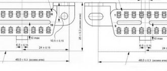
In the early 2000s, there were no strict requirements for the outer shape of the connector, and many automakers assigned the device configuration themselves. Today, there are two types of OBD 2 connector, designated Type A and Type B. Both plugs have a 16-pin output (two rows of eight pins) and differ only in the central guide grooves.
The pins in the block are numbered from left to right, with contacts numbered 1-8 in the top row, and numbers 9 through 16 in the bottom row. The outer part of the housing is made in the shape of a trapezoid with rounded corners, which ensures reliable connection of the diagnostic adapter. The photo below shows both device options.
Connector types - Type A on the left and Type B on the right
Basic steps in diagnosis
When you have found the VAZ 2114 diagnostic connector, you can begin the required diagnostic work.
By the way, before installing the device, think about what exactly it will be used for. When choosing an on-board device, you need to take into account the characteristics of the car, so inexpensive models are suitable for the VAZ 2114. It will be enough to choose a system that has a monitor, a set of wires, and the processor itself.
Next, you will need to find a place where you can mount the monitor. It is necessary to take into account the individual characteristics of the machine; the optimal place is the central part of the console. When there is not enough free space on the dashboard, you should mount the monitor on the dashboard.
Remember that you need to find a place for the processor, and it is important that the ventilation holes must be freely accessible. The case should be fixed in a certain place for greater reliability.
see also
The wires deserve special attention; they must not be damaged during operation. To do this, experts advise passing them through a special tube.
After the connector for diagnosing VAZs has been found, other work has been completed, and the wiring can be connected.
After the installation is completed, you can install the software and make the necessary settings.
Now you have access to car diagnostics.
Useful video
You can get more information about connecting to the diagnostic connector from the video below:
Any VAZ-2112 car is equipped with a system for self-diagnosis of faults, which can inform the owner about the presence of any fault without visiting a service station.
Such a system works by connecting special diagnostic equipment to it and further reading and decoding errors.
When is diagnostics required?
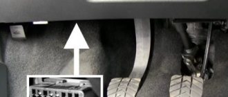
The first sign that the car system should be diagnosed will be the blinking of the CHECK ENGINE lamp located on the instrument panel. Please note that the presence of errors in the system will be the fact that after 10 seconds after starting the engine, the warning light will not go out and the error data will be stored in the ECU memory.
The error is indicated by an arrow.
Where is the connector?
In order to read all the fault codes that have arisen using diagnostic equipment, you will have to get to the diagnostic connector, which is located directly under the instrument panel console on the left side.
The location of the diagnostic block is indicated by an arrow.
You will detect it immediately as soon as you look at the approximate area of its location, since its characteristic shape is very specific.
Video “How to diagnose a car using OBD 2?”
The SUPER ALI channel showed the process of testing vehicle systems using a special scanner connected to the OBD 2 connector.
With the advent of microprocessor-controlled electronic systems in cars, it became necessary to check the operating parameters of the units themselves and the connecting electrical circuits. For this purpose, they began to use diagnostics using equipment called OBD (On Board Diagnostic). Knowing the location and standard pinout of OBD 2, you can check the car yourself.
Where is OBD 2 located?
Description of connector types
OBD 2 pinout
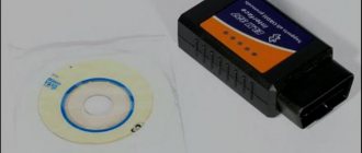
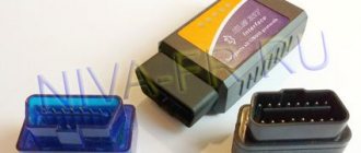
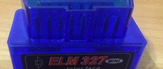
Video “Diagnostics using ELM327”
Comments and Reviews
Features of the diagnostic connector
Standard 12-pin connector for diagnostics
Depending on the year of manufacture of the car, the connector can be 10-pin or 12-pin. To connect to it you will need to make an adapter.
We make wiring
You can also throw a separate wire, but this is “collective farm”.
Diagnostics of modern car models is carried out using a special diagnostic connector. It connects to a computer, which analyzes the current state of the vehicle, determines the malfunction and indicates it. If you have the appropriate equipment, you can look for breakdowns even at home. However, not all VAZ-2112 owners can find the diagnostic connector right away. Today we’ll talk about its location on the classic panel and on the Europanel. In which part of the car should I look for the required socket?
On the back wall of the system unit
There are many connectors on the back of the system unit, some of which completely duplicate those located on the front. Their number can be completely different, again, it all depends on the motherboard model.
PS/2
Today this connector is considered obsolete, but on many motherboards it is still present and feels good, so to speak. Used to connect a mouse or keyboard. It is noteworthy that there are adapters from USB to PS/2.
COM port
It is almost impossible to find a COM connector on modern motherboards. Previously, it was used to connect all sorts of printers and other peripheral devices, which are now connected via USB. The COM port has an analogue - LPT, which is even less common; it has an oblong shape and is painted pink.
USB ports
As a rule, if there are 4 of these connectors in front, then at the back there are at least no less. Again, everything is done so that you can connect as many devices as possible to your computer at the same time. And if the front ports are usually occupied by all kinds of flash drives, then the rear ports are often connected to “long-lasting” devices, that is, which you will not constantly connect/disconnect. Well, for example, it could be a keyboard with a mouse, as well as printers and scanners.
There are two main types of these ports:
- USB 2.0
- USB 3.0
Of course, the third version is preferable due to its higher throughput; such a port is even marked in a different color - blue.
USB 2.0 and 3.0 are compatible with each other.
Network and Internet
One single connector is responsible for the network and the Internet - “Ethernet”, which is also sometimes called “RJ 45”. If you look closely, you will notice that there are small “windows” on this connector - these are indicators of network operation; when data is being transferred, they signal this. If the indicators do not light up, most likely the connector has stopped working and needs to be re-crimped (using a special crimp).
Video
Any monitor is connected to a computer (motherboard) using video connectors, which are located at the back. There are quite a lot of their varieties, it would not be entirely appropriate to talk about each one here, especially since the site already has a separate article about video connectors. In my opinion, only three of them can be called the most popular video ports:
- analog VGA port
- digital DVI
- digital hdmi
The rest are not so popular and are rare.
Audio
Usually - three or six inputs for connecting several speakers and a microphone. On budget segment boards, the number of audio connectors usually does not exceed three, but at the same time, all the necessary functionality is present, and this is:
- Red - for microphone;
- Green - for speakers;
- Blue - for connecting external sources, such as a TV, player or radio.
If your motherboard has six audio outputs, then know that the other three are used to connect additional speakers and a subwoofer.
Where to look for the connector
It is important to know that on different cars the required socket is located in different parts of the car. Moreover, on some AvtoVAZ models it may be in a completely different place compared to another car. Let's look at several VAZ cars as an example:
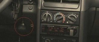
- on the VAZ-2112, as well as on the 2110, as well as 2111, the socket is located to the right of the driver’s seat, immediately under the column;
- on models 2108, 2109 and 21099, the socket you need is located under the glove compartment, on a special shelf;
- on cars with a europanel it can be found in the center of the console, near the cigarette lighter. A special decorative cover is used to disguise it;
- on Lada Kalina cars, the connector can be found near the gear shift lever. As is the case with cars with a Europanel, it is hidden under a special cover;
- on a Priora you need to look for it right behind the glove compartment, on the wall.
Thus, on the VAZ-2112 the diagnostic connector is located on the right side of the driver’s seat. It is located immediately under the steering column and, in principle, is not so difficult to find. Inspect the bottom of the panel.
Pinout
Knowledge of pinouts may be required if a car enthusiast wants to make an adapter for computer diagnostics with his own hands, or if you need to connect without one. Experts recommend buying ready-made devices without the need to make a plug yourself. However, if you do not have such an opportunity, and diagnostics need to be carried out urgently, we will consider two main pinout options used on VAZ cars of various years of manufacture. Until 2002, AvtoVAZ products used the following pinout option:
- The 4th and 5th pins are GND outputs.
- Pin 16 – +12 V (power line).
- The 7th contact is the diagnostic line itself.
Since 2002, the pinout scheme has changed significantly. Now it looks like this:
- Pin H – +12 V (power line).
- Contact G – +12 V for the fuel pump.
- Pin A – GND output.
- Contact M – diagnostic line.
There is one important note to note regarding this diagram. If you connect the connector without a block, but directly, it is recommended to use the charge from the cigarette lighter as a source of electricity. The peculiarity of this pinout is that contact H is not always routed in the car. The use of G is also not recommended because high frequency current is supplied. This can have a negative impact on the adapter, even to the point of burning it out. However, cases of burning out the fuel pump connector are quite rare. Therefore, if you wish, you can also use this option.
As you can see, the pinout on VAZ cars of different ages is sometimes very different. Therefore, we advise you to look at the registration certificate of your car and find out what year it is made. On older vehicles you will not find the new pinout design as it did not exist yet and on newer vehicles the old design was no longer used.
Reading time
Difficulty of the material:
For fans – 3 out of 5
To diagnose a VAZ 2114, 2113 or update the ECU firmware, car owners, diagnosticians or mechanics need to know the location of the OBD2 diagnostic connector, as well as its pinout and type. To flash the electronic unit or replace it, you also need to know the location of the ECU and the purpose of the pins.
Notebook-specific
It’s worth saying a few words about rare, I would even say “exotic” connectors that are found in laptops or some other devices, but which cannot be found on a regular PC. These are two connectors: PCMCIA (ExpressCard) and Kensington Lock. The latter is used to protect the device from theft. A special cord with a lock is inserted into the “Kensington Lock” connector and tied to any object, be it a table or a battery, for example. Naturally, only you have the keys to the castle.
ExpressCard
Kensington Lock
But the “ExpressCard” is a narrow slot covered with a plug into which a certain expansion card is inserted, on which ports for connecting other devices can be placed. With the help of such a card, you can easily add some USB 3.0 ports to your laptop, if only because there is a shortage of them on any laptop.
Well, that’s all, we have sorted out all the types of connectors that can only be found in a computer, if I suddenly missed something (the article is long, you understand) - write about it in the comments. Good luck to you and see you soon on the pages of pc-information-guide.ru!
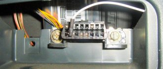
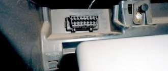
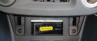
Where is the diagnostic connector for the VAZ-2114
VAZ 2108-2115 with a “European panel”, the diagnostic connector is located in front of the gearbox, directly under the cigarette lighter. The block is closed with a decorative cover. On injection models since 2002, a 12-pin rectangular connector has been used.
The location of the connector is indicated on the diagram in position No. 8 . The following are visual photos of the diagnostic block.
Photo of the block location:
About the ECU and its location is written in the article “Diagnostics of VAZ 2114”. The following shows the pinout of the OBD2 connector and the assignment of contacts of the electronic control units that were installed on the Fourteenth VAZ models.
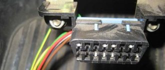
Connector type No. 1—16-pin OBD-II connector in the shape of a trapezoid:
Brands and years: some models after 2002 with control systems BOSCH MP7.0 Euro-3, BOSCH M7.9.7, January-7.2, January-7.3.
Connector type No. 2 - 12-pin rectangular connector: Make and year: all injection models, except for some models after 2002 that have an OBD-II connector
Types of connectors
In modern vehicles, two types of diagnostic sockets can be used - classes A or B. Both connectors are equipped with 16-pin outputs, eight contacts in each row. The contact elements are numbered from left to right, respectively, components numbered 1–8 are located at the top, and 9–16 at the bottom. The outer part of the body of the diagnostic block is made in the form of a trapezoid and is characterized by rounded shapes, which makes it possible to connect an adapter.
The main difference between the different types of connectors is the guide grooves located in the center.
Pinout OBD1 – 12 PIN (GM12)
Description:
OBD1 (GM12) connector is rectangular in shape, consists of 12 contacts.
Brands and years:
All injection models, except for some models after 2002, which have an OBD-II connector.
Access and location:
Open access. Located next to the ignition switch, partially covered by the steering column cover.
Pinout:
| M | L | K | J | H | G |
| A | B | C | D | E | F |
| Key * | |||||
* Connector Keying - A design element of a removable connector that ensures the correct orientation of the plug and socket.
Example in the photo:
Conclusions and their purpose:
| Conclusion | Color | Purpose |
| A | Weight | |
| B | L-line diagnostics (not always routed) | |
| D | CO potentiometer (not always diluted) | |
| G | Fuel pump control | |
| H | Power supply +12V (not always wired) | |
| M | K-line diagnostics |
OBD2 pinout – 16 PIN
Description:
The OBD2 connector is trapezoidal and consists of 16 pins.
Brands and years:
Gasoline passenger cars and light commercial vehicles manufactured or imported into the United States since 1996 (US CARB and EPA legislation) and in Europe (EOBD) since 2000-2001 (European Union Directive 98/69EG) and Asia (mainly since 1998). ).
Access and location:
Pinout:
| 1 | 2 | 3 | 4 | 5 | 6 | 7 | 8 |
| 9 | 10 | 11 | 12 | 13 | 14 | 15 | 16 |
| Smaller side of trapezoid | |||||||
Example in the photo:
Conclusions and their purpose:
| № | Color | Purpose |
| 2 | J1850 Bus + | |
| 4 | Body grounding | |
| 5 | Signal Ground | |
| 6 | Line CAN-High, J-2284 | |
| 7 | K-line diagnostics (ISO 9141-2 and ISO/DIS 14230-4) | |
| 10 | J1850 Bus- | |
| 14 | Line CAN-Low, J-2284 | |
| 15 | L-line diagnostics (ISO 9141-2 and ISO/DIS 14230-4) | |
| 16 | Power supply +12V from battery |
Diagnostic connector pins for used protocols
Pins 4, 5, 7, 15, 16 - ISO 9141-2.
Pins 2, 4, 5, 10, 16 - J1850 PWM.
Pins 2, 4, 5, 16 (without 10) - J1850 VPW.
The ISO 9141-2 protocol is identified by the presence of pin 7 and the absence of pins 2 and/or 10 on the diagnostic connector.
If pin 7 is missing, the system uses the SAE J1850 VPW (Variable Pulse Width Modulation) or SAE J1850 PWM (Pulse Width Modulation) protocol.
All three data exchange protocols operate via a standard OBD-II J1962 connector cable.
The correct connection diagram for a 12 PIN block with a 16 PIN adapter
OBD 2 Review
OBD 2 is a vehicle diagnostic device that first appeared in the United States in 1996. In Europe, this standard has been adopted as mandatory since 2001. Thanks to its widespread implementation, errors on machines of different brands have the same appearance.
The standard code contains the X1234 structure, where each character carries its own meaning:
- X is the only letter symbol that allows you to recognize the faulty system (engine, gearbox, electronic components, etc.);
- 1 – represents the general OBD standard code or additional factory codes;
- 2 – clarification of the location of the malfunction (power or ignition system, auxiliary circuits, etc.);
- 34 is the serial number of the error.
A special feature of the connector is the presence of a power plug from the on-board network, which allows the use of scanners without built-in or additional electrical circuits. The first diagnostic protocols provided only information about the presence of a problem. Modern connectors allow you to obtain more data about a malfunction by connecting diagnostic equipment with electronic units in the car.
Each device must comply with one of three international standards:
- CAN;
- SAE J1850;
- ISO 9141-2.
The video from the channel Sanek Zhelezniy Kaput presents a video demonstrating testing of the SsangYong New Actyon car through the OBD 2 connector.