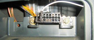
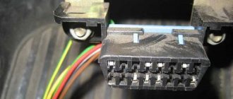
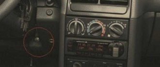
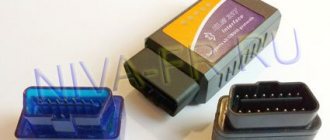
The diagnostic connector of a Priora car is a plug, by connecting to which you can identify 80% of breakdowns related to electronics. Of course, the diagnostic plug will not show whether the valve is bent or whether the pump is worn out, but believe me, it knows and can do a lot. Knowing this, car thieves take advantage of this. It’s very easy to steal any modern car, be it a Priora or an Infiniti, if you know where this connector is located.
The presence of a diagnostic connector on the Priora OBD is a vital necessity. In a modern car, it is often impossible to just look under the hood and immediately determine the problem. This is explained by the fact that the operation of all components of the car is coordinated by an electronic control unit - a small computer with which you need to find a common language.
You will have to use the diagnostic connector of a Lada Priora car at least once during its operation. Before buying a connector, you need to find out more about where the connector is located, how it is designed, what it is needed for, and what operation can be used to secure the Priora from theft. Read the article to the end and we will talk about the topics: diagnostic plug pinout, anti-theft protection, where to find it!
Anti-theft protection for connector
The connector also helps thieves.
By connecting to it, the attacker can easily turn off the car alarm, and his further actions will be predictable. The whole problem is that the thief knows in advance the location of the plug, which simplifies his life, and connects to it immediately after opening the car door. The plans of attackers can be ruined if the diagnostic plug is moved to another place in the car. This is most often done at service stations, so it is recommended to entrust this operation to specialists. If you do this yourself, you should first think about where to put the plug so that it “does not catch your eye.”
In words, everything is quite simple: remove the plug, disconnect it, put it in a new place and reconnect the wire block. In fact, you will have to dig a fair amount into the inside of your Priora, but it’s worth it if you want to take care of protection against theft.
The diagnostic plug will make life easier for the owner of a Lada Priora - instead of torturing yourself with a tool in your hand, digging in the engine compartment, you just need to get this “adapter”, find out the reason and only then start repairing.
The operation of the car control system is checked using special devices. Therefore, to test the vehicle, you need to find the Priora diagnostic connector and connect the equipment. The work takes minimal time. You just need to know the rules for connecting and using the test device.
Why is diagnostics needed?
The purpose of diagnostics, as stated above, is to accurately determine possible malfunctions that may occur during vehicle operation. If any symptoms of breakdowns appear in the operation of the car, but you cannot accurately determine the fault yourself, then you can try to diagnose the car.
But this is only a general purpose; more specific reasons for the check are listed below:
- The need to perform this process usually appears when indicators appear on the control panel that warn the car owner about a breakdown.
- In practice, this procedure is often carried out in the event of malfunction of one or more units and components of the car. The completed check will allow the car owner to give an accurate answer as to whether these mechanisms have really failed or not.
- When purchasing a vehicle. Thanks to computer error recognition, a potential buyer can determine without the help of specialists how correctly the power unit, gearbox and suspension are working.
- In addition, the need for this process may be due to a reduction in the possible costs of repairing the machine in the future. In other words, we are talking about preventive diagnostics; according to many experts, it is better to perform such a task at least once a year. If the car owner learns about possible malfunctions in advance, before the car becomes impossible to operate, then he will be able to reduce the financial costs of repairing it (the author of the video is the CompsMaster channel).
OBD 2 pinout
Pinout of the Lada Priora comfort block
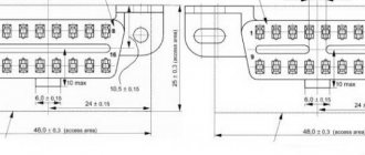
The layout and purpose of the contacts in the OBD 2 connector are determined by the standard.
Numbering of plugs in the connector
General description of plugs:
- 1 - reserve, this pin can output any signal that the car manufacturer sets;
- 2 - channel “K” for transmitting various parameters (can be designated as J1850 bus);
- 3 - similar to the first;
- 4 — grounding of the connector to the car body;
- 5 — diagnostic adapter signal grounding;
- 6 - direct connection of the CAN bus contact J2284;
- 7 — channel “K” according to ISO 9141-2 standard;
- 8 - similar to contacts 1 and 3;
- 9 - similar to contacts 1 and 3;
- 10 — pin for connecting the J1850 standard bus;
- 11 — pin assignment is set by the vehicle manufacturer;
- 12 - similar;
- 13 - similar;
- 14 - additional pin of CAN bus J2284;
- 15 — channel “L” according to ISO 9141-2 standard;
- 16 - positive output of the on-board network voltage (12 Volts).
An example of a factory OBD 2 pinout is the Hyundai Sonata, where pin 1 receives a signal from the anti-lock braking system control unit, and pin 13 receives a signal from the control unit and airbag sensors.
Depending on the operating protocol, the following pinout options are possible:
- When using the standard ISO 9141-2 protocol, it is activated via pin 7, while pins 2 and 10 in the connector are inactive. For data transmission, pins numbered 4, 5, 7 and 16 are used (sometimes pin number 15 can be used).
- With a protocol type SAE J1850 in the VPW version (Variable Pulse W >
Elm327 settings for Priora
Settings of the Torque Pro program for working with right-hand drive cars using the example of Toyota Mark II 2001 via ELM327
For right-hand drive Toyota Mark II (2001) Torque Pro, you need to write a command to programmatically reduce the speed of the ISO 14. and ISO 9. protocols (see the picture attached to the article)
For other models and brands of JDM (JDM-Japan Domestic MArket - Japanese domestic market), the following initialization lines should be entered to specify the protocol exchange rate:
Toyota Mark II 2001 y.o.: ATSP4n ATIB96n ATIIA13n ATSH82 13 F0n
Toyota Celica ZZT230: ATSH8213F1 n ATIB96 n ATIIA13
Toyota Vitz 01.2002: ATSH8213F1 n ATIB96 n ATIIA13, OBD2 protocol ISO 14230-4 (5b init, 10.4k baud)
Japan Domestic Market Nissan: ATSP5nATALnATIB10nATSH8110FCnATST32nATSW00
Japan Domestic Market Nadia/Harrier: ATIB96nATIIA13nATSH8213F1nATSPA5nATSW00
JDM Nadia/Harrier: ATIB96nATIIA13nATSH8213F1nATSPA5nATSW00
Toyota Common: baud rate - 10400 baud, ATIB10nATIIA13nATSH8013F1nATSPA4nATSW00
JDM Nissan(will test this with Xtrail): ATSP5nATALnATIB10nATSH8110FCnATST32nATSW00
Toyota Fielder: ATIB96nATIIA13nATSH8113F1nATAL
JDM Toyota Caldina Gt-Four( 2004 model) Protocol: ISO 14230-4(5b init, 10.4k baud), ATIB96nATIIA13nATSH8113F1nATSPA4nATSW00
For the rest of the majority of right-handed Toyotas, it is enough to write the initialization line: ATSH8213F1nATIB96nATIIA13
Source
General recommendations for connecting to the diagnostic connector
Replacing knock sensor Priora 16 valves
p, blockquote 49,0,0,0,0 —>
- Some sources indicate various methods for self-diagnosis of a car by connecting jumpers to the OBD connector. In emergency cases this is justified. If you have the opportunity, time and money (now very little, even with an on-site visit) for diagnosis by a specialist, it is better to resort to his help.
- If you have skills in working with a computer or Android devices, you can purchase a simple ELM327 scanner and then diagnose the engine yourself. More expensive multi-brand scanners such as AUTOCOM allow semi-professional diagnostics of most car brands. You can buy expensive diagnostics by sharing with your garage neighbors or co-workers. Such diagnostics can generate profit by providing “crappy” services.
- Do not obstruct the connector. After purchasing a car, try to find its location, as it may suddenly come in handy.
- If the scanner has difficulty entering the connector, do not use excessive force; check whether the contacts are bent or whether there are any foreign objects (paperclips, other small items) in the sockets. Sometimes, under increased load, the connector falls inside the socket, and you have to disassemble the casing.
- Do not connect dubious scanners or various homemade products to the connector. Since the connector is directly connected to the vehicle's control units, an incorrect connection can cause damage to the vehicle and subsequent repairs will be costly.
Read this article about how to diagnose a car yourself.
Video - where is the OBD 2 connector located on the Renault Scenic:
p, blockquote 51,0,0,0,0 —> p, blockquote 52,0,0,0,1 —>
12-pin rectangular connector (lada 12 pin)
A Ground B L-line of engine diagnostics (including the line for reading slow self-diagnosis codes), ABS (8192-Baud Serial Data) (not always wired) C AIR (not always wired) D SES-Lamp - self-diagnosis lamp line (not always wired) E K diagnostic line (160-Baud Serial Data) F TCC (not always wired). On some models - +12V power supply G Fuel pump control (not always wired) J K-line for airbag diagnostics (AirBag) (8192-Baud Serial Data) M K-line for engine diagnostics, ABS
16-pin trapezoidal OBD-II connector (lada Obd-2 16-pin)
2) J1850 Bus+ 4) Body ground 5) Signal ground 6) CAN-High line, J-2284 7) K-line diagnostics (ISO 9141-2 and ISO/DIS 14230-4) 10) J1850 Bus- 14) Line CAN-Low, J-2284 15) L-line diagnostics (ISO 9141-2 and ISO/DIS 14230-4) 16) +12V power supply from battery
Location
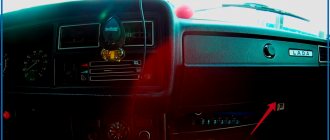
Often faced with a problem where the diagnostic connector is located. In each car they are installed differently, taking into account the specifics of the entire structure. As for Prior, everything here is done quite cleverly. If you don't know the exact location, it will be difficult to find.
Error code: Chevrolet Niva diagnostic connector: where is it located, diagram, description - Website about the famous domestic car Grant
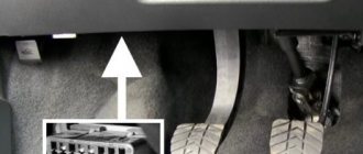
Car manufacturers have placed a diagnostic connector in the glove box. You can find it on the passenger side in the interior. Simply put, look in the glove compartment. If you contact service centers, specialists will immediately find the required design. Beginners need to be more vigilant in this matter.
It is best to work according to already compiled instructions. Let's take a closer look at the process:
- We completely open the glove box and clear it of foreign objects to make it easier to work.
- The glove compartment should hang on plastic guides on each side.
- We press on the side plates so that the small door opens further. This will make it easier to work and find the Priora diagnostic connector.
- We pull out the tabs on the side and completely remove the glove box from the latches.
- Provides access to the input plug for diagnostics. Now he is free and ready to go.
Access to the device is open. The following operations directly depend on the purpose of “opening” your car. More often they get to the connector to reconnect it or check the correct signals from the ECU. This way his work will be adjusted and will not create problems or unforeseen situations.
Glove compartment in a Lada Priora car
What is a diagnostic connector according to the OBD2 standard?
Replacing the upper engine mount of a Priora guitar
p, blockquote 5,0,0,0,0 —>
A little history
Manufacturers first started thinking seriously about automating vehicle diagnostics in the 70s. It was then that electronic engine control units appeared. They began to be equipped with self-diagnosis systems and diagnostic connectors. By closing the connector contacts, you can diagnose faulty engine control units using blink codes. As personal computer technology was introduced, diagnostic devices were developed to interface connectors with computers.
p, blockquote 6,0,0,0,0 —>
The emergence of new manufacturers on the car market and expanding competition predetermined the need to unify diagnostic devices. The first manufacturer to seriously approach this problem was General Motors, which introduced a universal information exchange protocol via the ALDL Assembly Line Diagnostic Link interface in 1980.
p, blockquote 7,0,0,0,0 —> adsp-pro-1 —>
In 1986, the protocol was slightly improved, increasing the volume and speed of information transfer. Already in 1991, the American state of California introduced a regulation according to which all cars sold here followed the OBD1 protocol. It was an abbreviation for On-Board Diagnostic, that is, on-board diagnostics. It has greatly simplified life for companies servicing vehicles. This protocol has not yet regulated the type of connector, its location, or error protocols.
p, blockquote 8,0,0,0,0 —>
In 1996, the updated OBD2 protocol had already spread throughout America. Therefore, manufacturers wishing to develop the American market were simply forced to comply with it.
p, blockquote 9,0,0,0,0 —>
Seeing the clear benefit of unifying auto repair and maintenance, the OBD2 standard has been extended to all gasoline-powered vehicles sold in Europe since 2000. In 2004, the mandatory OBD2 standard was extended to diesel cars. At the same time, it was supplemented with Controller Area Network standards for data exchange buses.
p, blockquote 10,0,0,0,0 —>
Interface
It is wrong to believe that the OBD2 interface and connector are one and the same. The interface concept includes:
p, blockquote 11,0,0,0,0 —>
- the connector itself, including all electrical connections;
- a system of commands and protocols for information exchange between control units and software and diagnostic systems;
- standards for the execution and location of connectors.
The OBD2 connector does not necessarily have to be a 16-pin trapezoidal design. On many trucks and commercial vehicles they have a different design, but the main transmission tires in them are also unified.
p, blockquote 12,0,0,0,0 —>
In passenger cars produced before 2000, the manufacturer could independently determine the shape of the OBD connector. For example, on some MAZDA vehicles, a non-standardized connector was used until the 2003 model year.
p, blockquote 13,0,1,0,0 —>
This is often a challenge for inexperienced auto electricians. The most common connector locations are:
p, blockquote 15,0,0,0,0 —>
- near the driver's left knee under the dashboard;
- under the ashtray;
- under one of the plugs on the console or under the dashboard (in some VW models);
- under the handbrake lever (often in early OPEL);
- in the armrest (occurs in Renault).
p, blockquote 16,0,0,0,0 —>
The exact location of the diagnostic connector for your car can be found in reference books or just Google it.
p, blockquote 17,0,0,0,0 —>
In the practice of an auto electrician, there are cases when the connector was simply cut off or moved to another location during repairs after accidents or modifications to the body or interior. In this case, its restoration is required, guided by the electrical diagram.
p, blockquote 18,0,0,0,0 —> adsp-pro-2 —>
Paper curtain
When supplying engine oil filters, manufacturers follow industry and government standards. Some characteristics, for example, the opening pressure of the bypass valve, are regulated by technical specifications.
Only companies whose products comply with international standards - ISO 4548 are suitable for the definition of leading brands. The human eye distinguishes hair with a thickness of 70 microns and 40 microns, but in the latter case it is already at the limit of visibility. Without a microscope, a person will not know what bacteria 2 microns in size and soot particles 0.6 microns in size look like.
Curtains of filter elements made of pleated and corrugated paper trap contaminants up to a maximum size of 40 microns. To increase filtration efficiency, synthetics are used.
With a two hundredfold magnification of the structure, you can compare the difference between paper and synthetics (left, right, respectively).
Structure of filter materials
The main differences between paper filters are:
- the presence inside a protective cage that retains pieces of paper when the cartridge is destroyed;
- Curtain ribs can be straight or zigzag, and can have different densities and quantities.
Cassette without protective clip
Zigzag filter fins
Unfortunately, it is almost impossible to see the density and number of curtain ribs through the threaded hole. But when compiling the next rating, experts cut non-separable cases and evaluate the specified parameters, making the information accessible to users.
Pinout of diagnostic connector VAZ 2114
Pinout and where is the diagnostic connector for VAZ-2112
Diagnostics of modern car models is carried out using a special diagnostic connector. It connects to a computer, which analyzes the current state of the vehicle, determines the malfunction and indicates it. If you have the appropriate equipment, you can look for breakdowns even at home. However, not all VAZ-2112 owners can find the diagnostic connector right away. Today we’ll talk about its location on the classic panel and on the Europanel. In which part of the car should I look for the required socket?
Where to look for the connector
It is important to know that on different cars the required socket is located in different parts of the car. Moreover, on some AvtoVAZ models it may be in a completely different place compared to another car
Let's look at several VAZ cars as an example:
- on the VAZ-2112, as well as on the 2110, as well as 2111, the socket is located to the right of the driver’s seat, immediately under the column;
- on models 2108, 2109 and 21099, the socket you need is located under the glove compartment, on a special shelf;
- on cars with a europanel it can be found in the center of the console, near the cigarette lighter. A special decorative cover is used to disguise it;
- on Lada Kalina cars, the connector can be found near the gear shift lever. As is the case with cars with a Europanel, it is hidden under a special cover;
- on a Priora you need to look for it right behind the glove compartment, on the wall.
Thus, on the VAZ-2112 the diagnostic connector is located on the right side of the driver’s seat. It is located immediately under the steering column and, in principle, is not so difficult to find. Inspect the bottom of the panel.
Pinout
Knowledge of pinouts may be required if a car enthusiast wants to make an adapter for computer diagnostics with his own hands, or if you need to connect without one. Experts recommend buying ready-made devices without the need to make a plug yourself. However, if you do not have such an opportunity, and diagnostics need to be carried out urgently, we will consider two main pinout options used on VAZ cars of various years of manufacture. Until 2002, AvtoVAZ products used the following pinout option:
- The 4th and 5th pins are GND outputs.
- Pin 16 – +12 V (power line).
- The 7th contact is the diagnostic line itself.
Since 2002, the pinout scheme has changed significantly. Now it looks like this:
- Pin H – +12 V (power line).
- Contact G – +12 V for the fuel pump.
- Pin A – GND output.
- Contact M – diagnostic line.
There is one important note to note regarding this diagram. If you connect the connector without a block, but directly, it is recommended to use the charge from the cigarette lighter as a source of electricity
The peculiarity of this pinout is that contact H is not always routed in the car. The use of G is also not recommended because high frequency current is supplied. This can have a negative impact on the adapter, even to the point of burning it out. However, cases of burning out the fuel pump connector are quite rare. Therefore, if you wish, you can also use this option.
As you can see, the pinout on VAZ cars of different ages is sometimes very different. Therefore, we advise you to look at the registration certificate of your car and find out what year it is made. On older vehicles you will not find the new pinout design as it did not exist yet and on newer vehicles the old design was no longer used.
Pinout of diagnostic connectors for VAZ and GAZ cars
Currently, the vast majority of cars have an OBD2 diagnostic connector (trapezoidal 16-pin block, usually located in the steering wheel area). Through this connector you can connect diagnostic equipment to diagnose your car, as well as connect on-board computers and other devices that work through the diagnostic connector.
People often have questions about the pinout of diagnostic blocks for some cars. In our store there are various adapters for different models. But if you forgot to order an adapter for your car, you can try to make it yourself, or connect the adapter directly. To do this, we have prepared for you a short review on the pinout of the OBD2 socket, the pinout of the sockets for VAZ and GAZ cars.
Do-it-yourself diagnostics
Various breakdowns of sensors and other devices can cause increased gasoline consumption, incorrect engine operation, and increased wear of car system components. Despite the presence of errors, the VAZ Priora will drive until the driver has to make expensive repairs because of them.
VAZ Priora car
So that the motorist does not suddenly have to face the need for repairs, a special controller is installed on the VAZ Priora, with the help of which the driver can diagnose breakdowns. This can be done either using special additional equipment or an on-board computer installed in the car.
In fact, to carry out diagnostics, the car owner will only need to press a few buttons and count combinations of faults.
For example, you do not have a special tester, so we will look at diagnosing the vehicle for errors using the on-board computer. The BC is built into the dashboard and can be used to read combinations of faults. To do this, you need to activate the auto test mode.
The arrows on the dashboard move to maximum values when performing self-diagnosis of the vehicle
- First, turn off the ignition. After this, hold down the daily mileage reset button and turn on the ignition. Please note: the button must be held down.
- There is an LCD indicator on the vehicle's dashboard, keep an eye on it. When you turn on the ignition, all icons will begin to light up, and all arrows (speedometer, tachometer, antifreeze temperature sensor, gasoline level status) will begin to move to the maximum values and back. That is, if all the arrows behave as described here, this means that the sensors and indicators are functioning correctly.
- Now you need to find the button for switching BC functions - it is located on the right steering column switch. By clicking on it, the software version (1.0 and higher) will be displayed on the screen.
- Click on this button again. Combinations of faults will begin to appear on the screen. If necessary, you can reset error data here. To do this, press and hold the daily mileage reset button for about three seconds.
The appearance of a fault combination on the LCD screen during self-diagnosis
Pinout diagram for OBD2 connector connection
p, blockquote 19,0,0,0,0 —>
The connection diagram for the pins of a standard OBD2 16-pin connector, used in most modern passenger cars, is shown in the figure:
p, blockquote 20,0,0,0,0 —>
p, blockquote 21,0,0,0,0 —>
p, blockquote 22,0,0,0,0 —>
- installed by the manufacturer;
- J1850 bus;
- installed by the manufacturer;
- car weight;
- signal ground;
- CAN bus high level;
- K-Line bus;
- installed by the manufacturer;
- installed by the manufacturer;
- J1850 bus;
- installed by the manufacturer;
- installed by the manufacturer;
- installed by the manufacturer;
- CAN bus J2284;
- L-Line bus;
- plus with battery.
The main ones for diagnosing are CAN and KL-Line buses. In the process of carrying out diagnostic work, they interrogate the vehicle's control units by exchanging information using appropriate protocols, receiving information about errors in the form of unified codes.
p, blockquote 23,0,0,0,0 —>
In some cases, the diagnostic device cannot communicate with the control units. This is most often due to a CAN bus malfunction: a short circuit or open circuit. Often the CAN bus is closed by faults in control units, for example, ABS. This problem can be solved by disabling individual blocks.
p, blockquote 24,0,0,0,0 —>
If communication via OBD diagnostics is lost, first check whether the original radio is installed in the car. Sometimes a non-standard car radio short-circuits the K-Line bus.
p, blockquote 25,0,0,0,0 —>
To be more sure, you need to turn off the radio.
p, blockquote 26,1,0,0,0 —>
Diagnostic signals from specific control units (ABS, SRS airbags, body, etc.) are usually directly connected to the terminals, the purpose of which is determined by the manufacturer.
p, blockquote 27,0,0,0,0 —>
How to remove and check the sensor
Access from above to the Priora DD is difficult due to the intake module located above it. The easiest way to get to the sensor is from below, first removing the engine protection or at least unscrewing and folding its front part. When working from above, you will have to do everything by touch. In any case, before starting work, it is necessary to disconnect the ground wire attached to the “negative” terminal from the battery.
To remove the crankcase protection, you need to:
- unscrew 5 nuts with a 10mm head;
- unscrew the 2 19 nuts installed on the back of the shield;
- remove protection.
- by pressing the metal latch of the DD connector, disconnect the block of wires going to the controller;
- using a 13mm wrench, loosen the bolt securing the sensor;
- Unscrew the bolt and remove it from the threaded hole, removing the sensor.
- We connect a multimeter to the DD terminals. We set the device to voltmeter mode, choosing a measurement limit of up to 200 mV.
- We take a metal object - pliers or a bolt - and lightly tap it on the DD.
When you tap on a working sensor, the voltmeter will show voltage surges. A faulty DD will not react in any way. A more accurate diagnosis of a removed sensor can only be done using a special stand.
Installation of a new DD is carried out in the reverse order of dismantling. Experts recommend installing a similar Bosch instead of the “native” one. Before going to the store for a new sensor, you should write down the markings of the removed sensor. Tightening the bolt securing it to 13 should be done with a slight force - 10.4–24.2 N m (1.1–2.5 kgf). Tightening too tightly will affect the operation of the sensor.
Problems with engine detonation can occur due to various faults. They are often associated with the operation of the electrical circuit from the knock sensor to the electronic control unit, or with the knock sensor itself. The diagnostic scanner can detect 4 common knock errors - P0325, P0326, P0327 and P0328.
Where is the diagnostic connector on the Lada Priora, location, diagram
Modern generation cars are equipped with a special electronic control unit, which is abbreviated as ECU. It is this unit that remembers any faults that may manifest themselves both in the car engine and in various electrical systems. To connect the unit to the equipment, a special connector is used for diagnostics. VAZ cars are equipped with a European standard OBD-II connector. Every VAZ owner must know where exactly the diagnostic connector is located in the Priora, unless, of course, he independently monitors the technical health of his car.
Location of the connector for connecting to diagnostic equipment
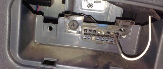
Finding the location of the connector with which the Lada Priora connects to diagnostic equipment is quite simple. This element is located immediately behind the car glove compartment, on the rear left wall. To be able to access the connector, you need to do the following:
- open the glove compartment;
- remove the glove box fastening clips;
- dismantle it.
The guideline for finding the location of the connector is the stove nozzle, which heats the passenger’s feet.
By drawing a conditional parallel line along the inside of the Lada Priora panel, you can see the element you are looking for, which is necessary for connecting to diagnostic equipment.
What is the diagnostic connector for?
Knowing exactly where the diagnostic connector is located, car owners will be able to independently check the technical serviceability of their four-wheeled friend at any time and promptly replace failed components. You can begin such a check after activating the test program. With the help of the latter it is possible to solve the following problems:
- adjust the fuel supply;
- find the cause of the transmission malfunction;
- promptly identify problems with the ECU firmware.
In order to check the operation correctly, you need not only to know the location of the connector, but also the rules for using the diagnostic device. Therefore, before purchasing a testing element, experts recommend carefully studying its features in order to accurately understand the diagnostic results obtained and promptly eliminate any, even minor, malfunctions.
Is it possible to move the diagnostic connector on the Priora to another location?
Quite often, car owners ask themselves: is it possible to choose a different location for the diagnostic device and is it possible to carry out such an activity independently? Why is this question of interest to car owners, because car thieves, who know exactly where the diagnostic connector is located on the Priora, quite simply disconnect the car from the alarm system and steal it without any problems. But if you move this element to another place, you can make the theft process several times more difficult and thereby prevent a possible crime.
It is, of course, possible to move the connector, but experts recommend seeking such a service at a service station so that professional staff can move this element correctly and accurately. If the car owner decides to carry out this activity on his own, then it must be carried out step by step and only for those drivers who understand connecting and disconnecting automotive electrical equipment:
- The wires are carefully disconnected from the connector.
- The device is slowly removed from the so-called socket.
- The connector is moved to another location.
- The connecting wires are reconnected.
Experts recommend installing the connector yourself near the gear shift knob or to the left of the steering column. By choosing a new location for the connector and doing this operation yourself, which, by the way, is quite simple and straightforward, only the driver will know exactly where the connector is located, but it will be very difficult for car thieves to find out about the new location.
Additional signals about the causes of the malfunction (1000)
- 102 – the DC heating resistance has disappeared;
- 115 – circuit failure of the same sensor;
- 123/124 - violation of mixture formation in the absence of load - idle is acting up;
- 127/128 – duplicates the previous signal in partial load mode – jerks, dips or jerks when pressing the gas pedal lightly;
- 135 – open circuit or short circuit of circuit DK1;
- 136/137 – violation of the formation of a combustible mixture at minimum load;
- 140 – potential difference between measured and actual load;
- 171/172 – incorrect operation of the potentiometer;
- 386 – incorrect detonation channel test result;
- 410/425/426 – short circuit to the sides or ground/break in the lines of the canister purge valve;
- 500/501/502 – open circuit with short circuit of the fuel pump for ground and 12V, respectively;
- 509 – overload of the XX regulator;
- 513/514 – short circuit of the throttle position in position XX;
- 541 – there is no power to the fuel pump or the integrity of the housing may be damaged with fuel getting inside;
- 570 – an incorrect signal from the APS design is received;
- 600 – no impulse is received from the APS; there may be a breakdown or the unit is coming off;
- 602 – 12V short circuit to the electronic engine control unit;
- 603 – problems with the firmware, can be resolved by rebooting;
- 606/616 – interruptions in the operation of the rough road sensor;
- 612 – incorrect ECU reset code – the system did not reboot;
- 617 – the rough road sensor has died or a short circuit has formed;
- 620 – critical fault in the EEPROM;
- 621 – critical RAM fault;
- 622 – failure or breakdown of the EEPROM;
- 640 – conflict in checking firmware status;
- 689 - diagnostics showed that all vehicle systems are in order - erroneous codes were displayed.
Error code: How to clear Mercedes check engine light
Where is the diagnostic connector for Lada Granta (diagram)
Thanks to the diagnostic connector, you can determine many parameters and display them on the on-board computer screen. In addition to the on-board computer, you can also exchange data with a smartphone using a Bluetooth adapter. A special application will also allow you to view some information.
Why do you need a diagnostic connector?
Every time the vehicle undergoes a technical inspection, the data is updated. If any breakdown occurs, it is likely that it will be much easier to fix it by receiving data about the condition of the car during maintenance by connecting to the diagnostic connector.
Diagnostics of this type is not a panacea for a breakdown: with its help, the average car owner is unlikely to determine the exact cause of the malfunction. The fact is that information can be displayed with serious deviations. Therefore, only a professional is able to determine the cause of the malfunction, based only on the data received from the diagnostic connector. However, sometimes, if the problem is obvious, this information can help any car owner - too large a deviation of the parameters from the norm excludes the possibility that the problem is an error.
Thus, the data will help determine the cause of the breakdown.
Where is the diagnostic connector located in the Lada Granta?
To find the diagnostic connector in Grant, you should look under the front passenger seat. In the place where the passenger's feet should be, there is a small space above which the glove compartment is located. On the left wall of this recess you will find a ventilation grille through which air is blown when the stove is on. Directly above this grille is the diagnostic connector.
To get to it and establish a connection, you will have to unscrew several bolts from the plug. The connector is quite large and has a distinctive appearance, so you are unlikely to miss it.
It is recommended to be careful when connecting the adapter to the diagnostic connector of the Lada Granta. The fact is that the location of the connector is not very convenient. Because of this, when the adapter is turned on, there is always a risk that a passenger will touch it with his foot. In principle, the adapter itself is held in the connector quite firmly. However, if a passenger hits it hard (and this most often happens completely by accident), he will easily break both the connector and the adapter. The simplest solution would be to either warn the passenger not to move their legs too actively (which does not always help), or not to ride with the adapter installed in the connector. Some car owners solve this problem radically - car service centers ask them to move the connector to another, safer and more convenient place. However, this will cost a decent amount.
How to use the diagnostic connector
The diagnostic connector allows you to read various information from the internal memory of the vehicle computer. With its help, a specialist can carry out diagnostics by examining error codes. In addition, data from sensors that display engine operation is also received through the diagnostic connector.
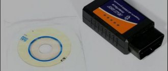
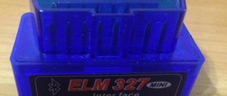
To use the connector, you need special equipment. The most common adapter is called ELM 327. It is small in size, easily connects to the connector, and then transmits data from the car’s memory via the Bluetooth interface. Using various programs, you can view the main parameters even from a smartphone (for example, using the Torque program).
This connector also includes an on-board computer and a scanner. With their help, error codes and various vehicle parameters are read. If during the diagnostics you have received error codes for some parameters, you should contact a specialist. The documentation should describe what exactly this error means.
Early Grant models did not have an engine temperature indicator on the dashboard. Therefore, the diagnostic connector was often used precisely to monitor this particular indicator. In general, it is most often used to display various engine parameters in digital form. Given the complexity of diagnostics, few car owners take it seriously.
Sometimes diagnostic connectors are used by car thieves. The fact is that the circuit provides a contact for monitoring the immobilizer. However, this method is used extremely rarely. If you still want to protect yourself from it, you should purchase a special circuit that distributes contacts differently. In this case, the hijacker will not be able to disable the protection.
Deciphering error codes
The Lada Kalina has a diagnostic connector when equipped with a self-diagnosis system, which is now installed on almost all modern cars. The presence of such a connector in cars is due to stricter inspection rules during technical inspections.
Engine diagnostics are carried out to identify hidden problems and defects, as well as to assess the performance of each mechanism.
Diagnostics of Lada Kalina, which can be carried out using a connector.
Diagnosing a fuel-injected car just seems complicated and incomprehensible. Many people believe that this is a matter for trained and experienced craftsmen, but you can check the operation of control systems yourself.
Self-diagnosis begins by connecting the diagnostic tester to the vehicle controller. This makes it easy to obtain diagnostic data and errors. Instead of a tester, you can use a special program by downloading it for free on any suitable resource.
The adapter designed for the connector comes with a special driver and software. The COM port that appears in the program must be rearranged to numbers 1,2, 3 or 4. These are the numbers with which the standard Kalinovsky connector works.
Each engine has its own standard parameters. These are technical characteristics that determine the normal operation of the motor. These parameters are compared with the values obtained during diagnostics. All measurements are carried out with the engine running at idle speed.
- Battery voltage level (UACC). To carry out the test, it is necessary to turn on all the most powerful sources of energy consumption. If the voltage reading on the diagnostic screen is less than it should be, you will have to check all electrical circuits separately. Normal values are from 14 to 14.5 V.
- Mass air flow (AIR). The indicator is determined by the mass air flow sensor. Without diagnostic equipment, checking air flow is impossible. To obtain the value, you need to press the gas pedal until the speed is 5000. If the sensor is working, the indicator rises to a level of 200-250 kg/h.
- Injection pulse duration (INJ). This is the time fuel is injected into the cylinder while each injector is open. Indicators that exceed the norm indicate that the injectors are most likely clogged and clogged. To fix the problem, the parts should be washed. The reasons may also be a clogged fuel filter or a pump failure. To accurately diagnose the problem, press the gas pedal. Normally, the indicators should be from 3 to 5 in a calm, idle state and from 15 to 20 when gasping.
- Oxygen indicator before the catalyst (ALAM1). It should not exceed 0.7 V and, reaching this figure, go back down. This indicates that the feedback is working properly.
- Number of idle speed control (FSM) steps. In other words, the idle speed control sensor. It is a stepper electric motor with a cone-shaped plug attached to the shaft. When the engine is idling, this figure is 40-60 steps, when accelerating - from 150 to 180 steps.
- Estimated fuel consumption (QT). For a complete diagnosis, check the pressure in the fuel rail and the voltage in the spark plugs. It wouldn't hurt to check the compression on the cylinders and find out the CO. However, for all these measurements, in addition to the diagnostic connector and standard equipment, you will need another, expensive device and the connection of experienced professionals. Therefore, here you will have to limit yourself to one indicator: from 0.6 to 0.9 l/hour at idle.
- Throttle Position (THR) value. This parameter is determined by a special sensor. If the throttle position value shows an error and malfunction, the car owner may notice some jerks with “dips” while driving. An increase in the number of idle revolutions will also indicate the presence of a problem. This parameter should be checked with the ignition on, but it is not recommended to start the engine itself. When you gradually press the gas pedal, the readings on the monitor should smoothly increase to 90%. It should be taken into account that it is impossible to achieve 100% - this is predetermined by the manufacturers. The sensor is considered operational if the procedure was successful. Idle speed should show 0%.
- Crankshaft and its rotation frequency (FREQ). The diagnostic figure will be displayed on the screen by a special crankshaft position sensor. The malfunction is easy to notice even without diagnostic equipment, because the engine simply will not start. Indicators from the sensor normally vary in the range from 800 to 840 rpm.
- Limit of uneven crankshaft rotation (LUMS_W). This figure should not exceed 4 rpm. Otherwise, you can be sure that there are misfires in the cylinders. With such a malfunction, it’s time to check the spark plugs and high voltage wires.
- Ignition timing (UOZ). Data from several sensors are combined into one indicator and calculated by the electronic control unit. The value varies from 6 to 15.
- 2 - overvoltage;
- 3 - malfunction of the device indicating the fuel level;
- 4 — the cooling temperature sensor does not work, the circuit may be broken;
- 5 - outside temperature sensor error;
- 6 - probable motor overheating;
- 7 — emergency oil pressure level;
- 8 - the brake system is faulty;
- 9 — battery is discharged;
- E - the error is contained in the data packet.
Cluster of marks
November 2014
| Mon | W | Wed | Thu | Fri | Sat | Sun |
| « Feb | Feb » | |||||
| 1 | 2 | |||||
| 3 | 4 | 5 | 6 | 7 | 8 | 9 |
| 10 | 11 | 12 | 13 | 14 | 15 | 16 |
| 17 | 18 | 19 | 20 | 21 | 22 | 23 |
| 24 | 25 | 26 | 27 | 28 | 29 | 30 |
