Operations performed when adjusting the pressure regulator drive on a VAZ 2170 2171 2172 Lada Priora
Improper adjustment of the pressure regulator transmission may cause the vehicle to skid or sideways during braking and reduce braking performance.
In addition, I would like to note that the pressure regulator for the Priora and the tenth family is identical, and therefore the pressure regulator can be adjusted according to the procedure for adjusting the pressure regulator on a VAZ 2110 2111 2112 car (instructions are attached to the color images).
Why do you need a brake force regulator?
The function of the regulator is to temporarily reduce the braking force during heavy braking. The fact is that force evenly distributed on the rear and front axles can lead to a skid of the car. If the rear brakes start working a little later and weaker than the front ones, this does not happen.
Based on the above, we can conclude that the sorcerer is an element of the car’s safety system, partly preserving its stability on the road when the brake pedal is pressed in an emergency. On modern models, this function is performed by ABS. That is why there is no need today to use a technically outdated device in production.
"CHEVROLE-NIVA"
By the way, before testing tires on cars without ABS, each time we slightly adjust the regulator taking into account the road condition (snow, ice, asphalt), ensuring that the rear wheels lock a little later than the front ones. Let's not break tradition. Our Shniva found the gap between the cheeks of the regulator to be 16 mm, which was adjusted using a stop screw.
Several brakings, and the braking distance from 80 km/h for a car with a partial load is determined: 34.4 m. With a full load... 33.6! Almost a meter shorter! At the same time, the driver noted a heavier pedal and rapid heating of the brakes, which required cooling before each measurement. Let’s remember these parameters and make adjustments to the “sorcerer” adjustment. First, let's reduce the gap to 8 mm. Now the regulator significantly limits the pressure in the rear brakes, transferring almost all the hard work to the front ones.
Braking has become more difficult, keeping the front wheels from skidding is not so easy - they lock very sharply and the car, naturally, loses control. However, the result, to our surprise, is the same as in the basic version: 34.4 m. At full load, you have to press the pedal much harder, the front brakes begin to overheat. The result is 37.8 m. This is 4.2 m more than with the basic adjustment (33.6 m).
How does a sorcerer work?
The regulator itself consists of a cylinder, valve, spring and rod. The latter is connected to the rear beam, which ensures the operation of the VAZ-2109 sorcerer. Also, brake fluid circuits pass through the rear brake pressure regulator. For their mounting on the device there are 4 threaded entries. » alt=»»> How does the sorcerer regulator work on a VAZ? During emergency braking, the front of the car is pressed to the ground, and the rear is raised. This causes the regulator rod to move, which blocks the flow of fluid to the rear cylinders. A spring located under the valve prevents it from closing completely. Therefore, the rear mechanisms still work, but later and weaker than the front ones.
Lada
“The sorcerer”, or, according to the catalogue, the pressure regulator in the brake drive, it was not for nothing that people received such an apt nickname: no one really knows how it works, but, they say, being faulty, it can present an unpleasant surprise - make the car dance in an emergency. braking. This is where the insidiousness of the “sorcerer” lies: during normal operation, without braking to the floor, its work or inaction is practically not felt, but when its help is especially needed, it may not come. The pistons have soured, the rod or drive lever has broken off, or you installed a new one instead of a faulty regulator, but for the time being you don’t know that the unit is defective or out of adjustment... How dangerous is this?
Let’s check in our experiment how “witchcraft” affects the effectiveness of the brakes at partial and full load of the Chevrolet Niva and Kalina and what the owner should be wary of if he does not monitor the condition of the regulator. We can simulate a malfunction, from excessive activity to complete inaction, with adjustments. Let us remind you that the regulator’s task is to reduce the braking force on the rear axle, reducing the likelihood of skidding when braking to skid. The regulator, mounted on the body and connected by an elastic lever to the axle beam, limits the pressure in the rear brake mechanisms depending on the position of the rear of the body relative to the road, that is, on the vehicle load.
Setting the brake force regulator
Adjustment of the sorcerer should be done on an overpass or inspection hole. At the same time, the car is unloaded and driven to the work site. To perform the manipulation you will need:
- Socket wrench 13 or corresponding socket;
- Drill diameter 2 mm.
To adjust the sorcerer, use a wrench to loosen the bolt securing it to the lever bracket. Next, use a screwdriver to move the bracket until the resulting gap allows you to insert a prepared two-millimeter drill into it. After this, the bolt is tightened.
Note: the brake pressure regulator of the VAZ-2110 and previous VAZ models turns sour during operation so that it is not possible to move its bracket. In such a situation, you should pour WD-40 liquid over the rusted area, wait 15-30 minutes, and then use a hammer to move the part to the side using a soft drift.
We adjust the sorcerer on VAZ 2108-VAZ 21099
Note! We recommend going to the article about the whereabouts of the sorcerer (as well as a lot of interesting things) “Brake pressure regulator and why does a car need it?”
1) At the very beginning of the operation, drive the car into the inspection hole and press on its rear so that the car’s suspension is in the middle position.
Note! It is recommended to make adjustments with the machine unloaded!
2) Next, using a 13mm wrench, loosen the bolt securing the regulator to the lever bracket.
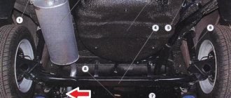
3) Having loosened the bolt, insert a wire (drill) of suitable thickness into the gap located between the lever and the lever spring (the place where the wire is inserted into the gap is indicated by a red arrow). But for the wire to enter, at the same time move the bracket with a screwdriver until the wire enters the gap (the place where the bracket is moved with a screwdriver is indicated by a blue arrow).
Note! The thickness of the drill/wire is "2.0-2.1mm", otherwise the sorcerer will not be able to be adjusted normally.
4) And at the end, tighten the bolt securing the sorcerer to the bracket until it stops.
Note! After tightening the bolt, do not forget to remove the wire!
Replacing the brake pressure regulator
The replacement of the sorcerer on VAZ-2110 cars and other vehicles equipped with an RTD is carried out on an overpass. You need a 13 mm spanner, a powerful screwdriver and a special 10 mm wrench designed for unscrewing brake pipes. Before starting work, the assembly must be cleaned of dirt and rust, doused with WD-40 or another penetrating compound, and then wait half an hour.
Work begins by unscrewing the bolt securing the bracket to the spring. Afterwards, the brake pipes are dismantled, the position of which is recommended to be pre-marked.
You can also unscrew the tube fittings with a regular wrench. However, using a special tool makes the job easier and reduces the likelihood of “licking” the edges. After the fittings, unscrew the two bolts securing the sorcerer to the body and remove the part. » alt=»»> It is necessary to install the new VAZ-2110 sorcerer in strict reverse order. After installing it and before adjusting the RTD, you should bleed the rear brake circuits. Next, the above-described procedure for setting up the sorcerer is performed.
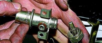
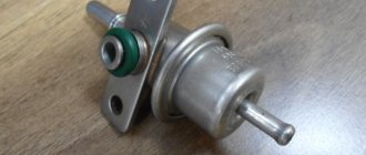
Methods for checking fuel rail pressure
The procedure for measuring the pressure in the VAZ 2114 ramp is carried out to identify a malfunction in the supply of gasoline to the injectors.
There may be several signs of a fuel system malfunction:
- instability in the operation of the car engine (motor trouble);
- increased volume of carbon monoxide at the outlet;
- unreasonably increased consumption of gasoline (increase to 30-50%);
- failures in the operation of the power unit;
- drop in engine power with a normally operating electronic control unit.
The first thing the car owner needs to do after identifying these malfunctions is to measure the pressure in the ramp.
Before work, you need to prepare the following tools and materials:
- pliers;
- screwdriver;
- sanitary linen;
- fuel or oxygen hose (internal diameter must be at least 8 mm);
- mechanical pressure gauge with a measurement limit of up to 7 atmospheres;
- several clamps;
- container for draining fuel;
- cap for twisting nipples.
Before starting work, you must ensure that the fuel system is tight. If you take measurements in the presence of microcracks or leaks, the results will be unreliable.
- We wrap plumbing flax under the pressure gauge nozzle, screw it into the hose and secure it with a clamp.
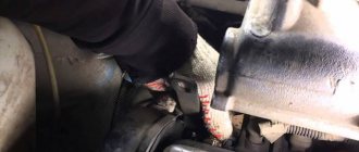
- Use your hands or pliers to remove the cap from the fuel rail.
- Using the cap, unscrew the nipple and put on a hose with a pressure gauge. We secure the connection with a clamp.
- We start the engine and record the pressure gauge readings.
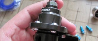
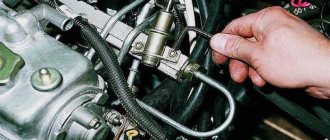
- To check the pressure regulator, disconnect the hose leading from the regulator to the intake manifold. In this case, the pressure gauge should show an increase in pressure to 3-3.2 atm. If the pressure readings do not change, there may be a problem with the fuel pump.
- Now you need to measure what maximum pressure the pump develops. Using pliers, the return fuel line is pinched. The new pump should show at least 6 atm. If the pressure gauge registers 5 atm, then the pump is already very worn out, but can still continue to work for some time. The pump is clearly faulty if the reading is less than 4 atm.
- We check the condition of the pipeline. To do this, we find the fuel pump assembly (under the rear seat) and determine the type of connection. A quick-release connection can be purchased in a store for literally pennies. If the connection is threaded, then the entire pipe is purchased and the tip is cut off. We put a hose with a pressure gauge on one end of it, and connect the other to the pump outlet. Now let's check the pressure. If the pressure gauge shows 6 atm, then we simply flush the entire system and replace the fine filter. When replacing the filter, direct the gasoline supply hose into a previously prepared container and turn on the ignition. We carefully inspect the fuel that has spilled into the container, install a new filter and repeat the procedure again. If after the new filter the gasoline is dirty, be sure to wash the injectors.
Examination
The operation of the VAZ-2109, 2110 and other AvtoVAZ models is checked on the move, in closed areas. To do this, accelerate the car to a speed of 40 km/h and sharply press the brake. The rear wheels should lock 1/2 second later than the front wheels.
The wheels are monitored by an assistant located outside the car. If wheel locking occurs noticeably later or does not occur at all, and also if the rear axle is locked simultaneously with the front, the sorcerer adjustment procedure is repeated.
To increase the response time of the rear brakes, the gap between the adjuster and the bracket is increased; to shorten it, it is reduced accordingly.
All the best! I was tormented by the wobbly brakes on the car, although everything is new in a circle, pads, drums, cylinders, springs... I decided to check what it was, the result is that the ass brakes sluggishly, and the rear left one is not at all clear how it is. no way. I thought the problem was in the tubes, but experimentally they determined that the problem was in the sorcerer. We begin to pump the second circuit (rear left, front right) and on the rear left the pedal goes a centimeter and stands as if dug out, although it should be pressed to the floor. My father and I scratched our heads for a long time, and in the end, after looking at the sorcerer’s device, it was decided to bleed the rear left with the valve not fully pressed (actually that
"LADA KALINA"
We set the regulator so that the rear is slightly late in locking the wheels. With this setting and partial load, the car needed only 27 m to stop. Fully loaded - 29.5 m. There are slight difficulties in preventing the front wheels from skidding. We reduce the gap in the regulator to zero - the half-empty Kalina stops after 31.8 m. The braking distance increases by 4.8 m, accompanied by a sharp blocking of the front wheels. The loaded one slows down after 35.2 m, the deterioration is even greater - 5.7 m! The pedal effort is increased and the brakes become noticeably hot.
Now we move the adjuster so that the rear brakes work as efficiently as possible. At partial load, the rear wheels suddenly lock and the car drifts off course—you have to release the pedal. On the verge of blocking it is very difficult to brake. The result is 30 m, which is 3 m worse than the “norm”. Full load gave a result of 26.9 m, which is 2.6 m better than the base (29.5 m). There are no comments regarding deceleration control. At the basic position of the regulator, the braking distance increases with increasing load. At partial load the spread of results is 4.8 m, so the base position is most effective. When you deviate from it in any direction, the braking distance increases.
- On a fully loaded vehicle, depending on the position of the regulator, the spread of the braking distance is 8.3 m.
- The best results, as on the Niva, come with increasing pressure in the rear brakes.
- However, on a slippery road, even in smooth turns, early locking of the rear wheels is possible, leading to a skid.
- And at partial load, with the regulator position different from the base one, the braking distance only increases.
Checking the brake pressure regulator for souring:
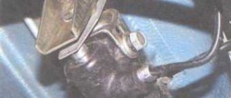
Have a helper press the brake pedal while you watch the pressure regulator rod (1), which should extend from the regulator body and act on the spring plate (2), pressing it against the drive lever (3). If the following sequence of operation occurs when you press the pedal, then all that remains is to adjust the “sorcerer”. It is advisable to check the adjustment of the sorcerer during each technical inspection, as well as during the replacement of springs and struts, and repair work on the rear beam.
Parking brake device
The main element that activates the brakes is the cable. The cable is better when it consists of a large number of thin veins with a diameter of 0.01 mm. These thin steel wires are twisted and twisted into one rope. If the cable consists of one wire, then its reliability is less, since it is a single-core cable that is easy to break. The cable material is high-strength steel.
The diagrams show the design of a mechanical parking brake of the mechanical type.
Mechanical type parking brake system drive: 1 – lever fixation button; 2 – parking brake drive lever; 3 – protective cover; 4 – traction; 5 – cable equalizer; 6 – adjusting nut; 7 – lock nut; 8 – cable; 9 – cable sheath
Rear wheel drum brake mechanism: 1 – hub fastening nut; 2 – wheel hub; 3 – lower tension spring of the pads; 4 – brake pad; 5 – guide spring; 6 – wheel cylinder; 7 – upper tension spring; 8 – expansion bar; 9 – finger of the parking brake drive lever; 10 – parking brake drive lever; 11 – brake shield
According to the manufacturing technology, the cables are hardened and lubricated in order to minimize the friction force that occurs in the cable casing.
On the outside, the cable is wrapped in metal wire and covered with a polymer material (rubberized plastic). At the ends, the cable shell has special steel shells and sleeves that are pressed into place.
1 — lever; 2 — button; 3 — thrust spring; 4 — latch rod; 5 — cover; 6 — front cable; 7 — rear cable guide; 8 — spacer sleeve; 9 — tension spring; 10 — spacer bar; 11 — lever for manual drive of brake pads; 12 - rear cable.
Working principle of manual mechanical brake with drum brakes:
- The driver raises the brake handle until a certain click is heard. If the cable is tightened, then perhaps you can only put it on the first latch with more force. If it is too weak, then even with the last latch the brake pads will not secure the wheels 100%!
- The rod pulls the main cable, and it pulls the secondary cables through the mounting bracket.
- The lever that is located inside the brake drum begins to turn and the spacer bar equally moves the pads apart, as a result of which the pad linings are pressed against the drum and do not allow it to rotate.
- When the driver lowers the handbrake, the cables are loosened, the springs in the drums return the spacer and the lever (the one in the drum), the pads are compressed and no longer act with their linings on the drum.
On cars with disc rear brakes, the principle of operation of a mechanical handbrake is approximately the same. The cable pulls a lever, which in turn compresses the brake disc. The lever on disc brakes is mounted behind the hub and on the outside.
Operating principle of the electronic handbrake:
- The truck driver presses the handbrake button, the electronic unit receives the command.
- The controller includes 2 electric motors with gearboxes that are installed on the rear wheels.
- Electric motors compress the brake pads around the disc. The sensor determines how hard to compress the pads. If the brake pads are worn down, the pads compress with greater force.
- To disable the electromechanical handbrake, just press the button.
Pros of an electronic brake:
- If the driver forgot to turn off the parking brake, then after starting the internal combustion engine while starting the car, the controller will release the pads.
- To unlock the rear wheels, the driver will not be able to release the brake by simply pressing. You must first start the engine, buckle up, put your foot on the brake and press the button.
- On vehicles with electric brakes, there is an Auto Hold anti-recoil button. When the car stops with the internal combustion engine running, the wheel locking is automatically activated immediately. This allows drivers to take off on different inclines.
Electronic brakes are more reliable than mechanical ones, although electric brakes have this disadvantage: they will not work with a dead battery. Mechanical brakes are simple in design, but a common cause of failure or reduced effect is cable contamination, stretching or breakage.
Signs of a working brake pressure regulator
A working regulator (3) should show no signs of brake fluid leakage, the rod should be movable, and the gap between the drive lever and the plate should be 2 mm.
Malfunctioning Sorcerer
If you find that the gap between the lever and the plate (3) does not match or the sorcerer is immobile, you should replace or adjust it.
Possible malfunctions of the regulator
In general, there are few malfunctions that a sorcerer can experience. This includes:
- Valve jamming;
- Position misalignment;
- Brake fluid leak.
The Settings Mismatch Wizard can be configured. You can determine the need for adjustment by how the car behaves when the brakes are applied. If the regulator is not adjusted correctly, the car begins to roll to the side.
If the valve is jammed or there is a fluid leak, the mechanism must be replaced. In theory, this can be repaired. However, the process of such repairs is complex and expensive, which makes it unprofitable.
Where is the voltage regulator located on the Priora?
Surely, many prior leaders have encountered such a problem. I'll outline the situation. I was driving late one evening and noticed that when I changed gears the low beam dimmed. Not for long, after a second or two it levels out. I switched to the voltmeter readings on the instrument panel. Everything is in order, 14.2V, I accelerated to 3000 rpm and I observe the picture: when the rpm drops to idle, the voltage drops to 12.4V, the headlights dim, then gradually becomes brighter, the voltage is again 14.2V. After driving like this for a couple of days, reading the Murzilka, I found out what the problem might be. In brushes. My generator is KZATE 115A. I looked at the catalog number of the relay regulator and went to buy it.
Next is replacement. This is where I seized upon grief, tearing my hands bloody and cursing AvtoVAZ... It turned out to be difficult to get to the generator, and it was also -14 outside, it was cold. Well, okay, let's get started, then. I removed the terminal from the battery, removed the air cooler housing, unscrewed the fastening of the air conditioner tube, this was enough, as it seemed to me, to stick my hand in there.
The voltage regulator and generator brush holder on the Lada Priora are removed for replacement in case of failure. Repair work can be carried out without dismantling the generator, but for clarity, the process will be shown with it removed. Prepare a standard set of tools and perform the following sequence of actions:
First of all, you need to de-energize the car by disconnecting the minus terminal from the battery.
- Disconnect the connector with the wire from the D+ terminal of the generator.
- Then remove the rubber protective cover from the contact pin.
- Having removed the cover, unscrew the nut and remove the wire terminal from the stud.
- Now unscrew the nut securing the generator excitation circuit terminal.
- Remove the excitation circuit terminal from the stud.
- Unscrew the nuts securing the protective cover of the generator.
- We remove the casing.
- Unscrew the three nuts securing the voltage regulator housing.
- Now unscrew the screw securing terminal D+ to the regulator bus.
- And remove the rectifier unit from the generator.
Before installing a new one, check the ease of movement of the brushes in the brush holder, as well as the amount of their protrusion, which should be at least 5 mm.
Welcome! Voltage regulator - it is installed on the generator and is directly connected to it, thanks to it, the entire current that the generator gives out changes and flows more evenly, for example, the more you turn the engine of a car (increase the speed, that is), the generator will work stronger and much more give out current, all this happens because the generator is connected to the engine (namely, it is connected to the crankshaft), but the voltage in the on-board network will also change from this (The more current the generator gives, the stronger this current increases in the entire on-board network car), therefore, when the speed increases, the light will constantly burn stronger, and when it decreases, it will dim because the current strength will decrease, so no matter what happened, a voltage regulator was invented, thanks to which the current strength in the on-board network always remains the same, but it changes when you turn on additional devices that need more current, that is, for example, you turn on the high beam headlights of a car and the current supply increases through the regulator so that there is enough power for these headlights, in addition, the current supply flowing through The regulator is constant and does not jump higher or lower, so the headlights work in the same mode and do not shine either stronger or weaker.
Note! In order to change or check the voltage regulator, you will need: Two different types of screwdrivers, as well as two wrenches that will be “12” in size, and you will also need a DC voltmeter thanks to which you can clearly determine what voltage you have in your on-board network and whether it is jumping, and among electrical appliances, a megohm meter is also useful, thanks to which you can check the regulator’s capacitor for serviceability, thanks to which the current strength remains constant when supplied to the on-board network!
Where is the voltage regulator located? It is located on the generator itself, as was already said a little earlier, a plus wire and a wire block are also suitable for it, so that the regulator does not become dirty; for this purpose it is also closed with a plastic cover, in more detail the pin that comes out of the regulator you can look at photo which is located below, in this photo you can just see the same plastic cover that closes the regulator, and in the other photo (Small) you can see that the cover has already been removed and only one pin sticks out, which comes from the regulator (This pin is on both indicated by a red arrow in the pictures).
When should you change the voltage regulator?
Design and principle of operation of the regulator
The VAZ brake pressure regulator is included in the drive circuit, which ensures the activation of the brake mechanisms of the rear wheel pair. Its main functional task is to correct the pressure in the drive circuit of the rear brake mechanisms, depending on the position of the car body relative to the rear axle, or on the vehicle load. The nature of its operation is similar to the operation of a limit valve, since it also interrupts the flow of brake fluid to the rear brake mechanisms, thereby minimizing the likelihood of “skidding” of the rear wheel pair.
The main structural elements of the pressure regulator are:
Torsion lever (item 1).
The regulator is mounted using a bracket and is connected to the rear axle beam using a torsion lever and rod. In addition, in the internal space of the regulator housing there are two cavities, one of which (pos. A) is connected to the main brake cylinder (hereinafter referred to as the GTZ), and the other (pos. B) is connected to the wheel brake cylinders.
The inoperative state of the regulator assumes the following positions of the main elements:
The torsion lever and spring (pos. 9) exert pressure on the piston (pos. 10), which rests against the plug (pos. 6).
In this case, gaps are formed between cavities “A” and “B”, which makes it possible to equalize the pressure in them and in the hydraulic brake drive.
During the braking process, under the influence of inertial forces, the rear of the vehicle moves upward, which helps to reduce the pressure from the torsion arm on the piston. Due to the larger area of the upper end of the piston, the pressure force acting on it will exceed the counter pressure force, which will lead to the lowering of the piston. At the moment the piston reaches the lower position and enters the seal, the communication between cavities “A” and “B” is interrupted, which initiates the occurrence of a pressure difference in them. The pressure in cavity “B” will decrease by an amount that determines the balance of the piston, that is, the amount of braking torque in the brake mechanisms of the rear wheel pair is adjusted.
How to check the pressure in the fuel rail of a VAZ 2114
In order to find out what level of gasoline pressure is maintained in front of the injectors, you need to find out where the TR is located, inspect the fuel supply hoses to the RTD and the “return” hose, that is, the hose through which excess gasoline is drained into the fuel tank. You will need to work with these tubes when measuring the gasoline pressure in the TR. In addition, you need to prepare the necessary tools and materials:
- a pressure gauge, for measurements it is best to take a mechanical one, with the least possible readings - 7-10 kg/cm2. because a pressure gauge with large readings will give a large measurement error;
- a hose that can operate under high pressure, preferably fuel or oxygen, with an internal diameter of 8 - 9 mm
- 2 - 4 clamps for securing hoses
- screwdriver and pliers
- cap for twisting nipples in car tires
- a container, preferably wide, to collect fuel when it is drained into the TR
- rags
Measuring pressure in the fuel rail must be carried out in four modes:
- with the ignition on - in this mode the pressure should be at least 2.9-3.0 kg/cm2.
- in low speed or idle mode - pressure is not less than 2.5 kg/cm2.
- with the hose disconnected from the RTD - the pressure is maintained within 3.3 kg/cm2.
- with a pinched hose for draining excess fuel back into the tank - the pressure increases to 7.0 kg/cm2.
- when overgassing, it increases abruptly to three and then drops to two and a half atmospheres
After everything is prepared, you can start working.
Attention! Before you start taking measurements, make sure that the fuel system maintains a tight seal and that there are no leaks or microcracks anywhere. Otherwise, the measurement results will be unreliable
- Insert a pressure gauge into one end of the prepared hose and secure the connection tightly with a clamp.
- At the fuel pressure fitting, located in the free end of the TP, opposite to the one on which the RTD is located, unscrew the plastic cap covering the nipple.
- Place an empty container to collect gasoline and press the cap to twist the nipples to release the residual pressure in the fuel rail;
- Without removing the container, unscrew the nipple using the same cap. The locking nipple is absolutely identical to those installed in car wheels.
- After this, put the free end of the hose prepared for testing onto the fitting. Before doing this, put a clamp on the free end.
- Tighten the clamp securely on the fitting, avoiding any leakage.
- Using a fuel pump, pump fuel into the TR.
- Turn on the ignition and use a pressure gauge to check the pressure created in the cavity of the fuel rail. It should be 2.9-3.0 kg/sq.cm. not less. If the readings drop to zero, it means the fuel pressure regulator or fuel pump check valve is faulty.
- The next step is an idle test. Start the car engine and check the pressure gauge readings. The arrow must be in a position of at least 2.5 kg/cm2. If in this mode a pulsation of up to 0.2 atmospheres occurs, then it is necessary to clean or replace the coarse filter in the fuel tank.
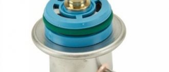
- Before measuring the pressure in the fuel rail to check the RTD, it is necessary to disconnect the vacuum hose coming from the intake manifold from it. The pressure should increase to 3.3 kg/cm2. a value of 3.0 atmospheres is also considered acceptable. If it does not change, or changes slightly, then, with a high degree of probability, the fuel pump in the fuel tank has failed.
- Finally, the pressure is checked with the return line turned off. To do this, use pliers to pinch the return hose running from the RTD to the fuel tank, through which excess gasoline is discharged. The pressure should increase to a maximum of 7.0 kg/cm2. A value of 6.0 atmospheres is considered acceptable, and anything lower indicates severe wear of the pump. Drop less than 4.0 kg/cm2. indicates a clogged fine filter or pipelines in this line.
The fuel system of a modern car is the most important line that feeds the internal combustion engine and ensures its performance. Its condition determines how efficiently and economically it will work, and sometimes the safety of the entire car depends.
Therefore, an important task for the motorist is constant vehicle prevention.