A high-quality color diagram of the electrical equipment of the domestic passenger car VAZ-21074 is provided to help auto electricians and service stations. Model 21074 is an improved modification of the VAZ-2107. The “seventy-four” is equipped with the same 1.6-liter engine, but the carburetor is replaced with an injector. Some elements of the circuit are installed not on all, but only on part of the produced cars of this model. At the end of the article, fuses and the circuits they protect are shown. Schemes are enlarged by clicking.
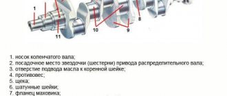
Electrical equipment VAZ-21074
- 1- block headlights;
- 2- side direction indicators;
- 3- rechargeable battery;
- 4- starter activation relay;
- 5- carburetor electro-pneumatic valve;
- 6- carburetor microswitch;
- 7- generator 37.3701;
- 8- gearmotors for headlight cleaners*;
- 9- fan motor activation sensor;
- 10- electric motor of the engine cooling system fan;
- 11- sound signals;
- 12- ignition distributor;
- 13- spark plugs;
- 14- starter VAZ-21074;
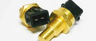
- 15- coolant temperature indicator sensor;
- 16- engine compartment lighting lamp;
- 17- low oil pressure indicator sensor;
- 18- low brake fluid level indicator sensor;
- 19- windshield wiper gearmotor;
- 20- carburetor electro-pneumatic valve control unit;
- 21- ignition coil;
- 22- electric motor of the headlight washer pump*;
- 23- electric motor of the windshield washer pump;
- 24- mounting block;
- 25- windshield wiper relay;
- 26- hazard warning and direction indicator relays;
- 27- brake light switch;
- 28- reversing light switch;
- 29- ignition relay;
- 30- ignition switch;
- 31- three-lever switch;
- 32- alarm switch;
- 33-plug socket for a portable lamp**;
- 34- heater fan switch;
- 35 - additional resistor of the heater electric motor;
- 36 - indicator lamp for turning on the heated rear window;
- 37 - indicator lamp for insufficient brake fluid level;
- 38 - signaling unit;
- 39- heater fan electric motor;
- 40 - glove box lighting lamp;
- 41 - lamp switch on the front door pillars;
- 42- switch for alarm lights of open front doors***;
- 43- alarm lights for open front doors***;
- 44- connecting block;
- 45- cigarette lighter;
- 46- watch VAZ-21074;
- 47- switch for instrument lighting lamps;
- 48- diode for checking the serviceability of the warning lamp for insufficient brake fluid level;
- 49 - fuel level indicator;
- 50 - fuel reserve indicator lamp;
- 51- speedometer;
- 52 - turn signal indicator lamp;
- 53- indicator lamp for closing the carburetor air damper;
- 54 - battery charging indicator lamp;
- 55- carburetor air damper closed warning switch;
- 56 - instrument cluster;
- 57- econometrician;
- 58- courtesy light switches on the rear door pillars;
- 59 - coolant temperature indicator;
- 60 - tachometer 21074;
- 61- parking brake indicator lamp;
- 62 - low oil pressure indicator lamp;
- 63- high beam indicator lamp;
- 64- indicator lamp for turning on external lighting;
- 65-voltmeter;
- 66- parking brake indicator switch;
- 67- switch for external lighting lamps;
- 68- rear window heating element switch with backlight;
- 69- switch for rear fog lights with on/off indicator*;
- 70 - fog light circuit fuse;
- 71- lampshade;
- 72 - rear lights VAZ 21074;
- 73 - level indicator and fuel reserve sensor;
- 74- pads for connecting to the rear window heating element*;
- 75 - license plate lights.
VAZ 21074 engine control system diagram
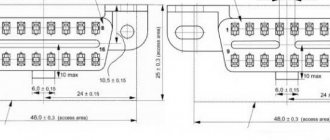
Wiring diagram of electrical connections of ECM VAZ 21074 - circuit elements. 1 – controller connector; 2 – mass air flow sensor; 3 – coolant temperature sensor; 4 – crankshaft position sensor; 5 – throttle position sensor; 6 – oxygen concentration sensor; 7 – speed sensor; 8 – ignition module; 9 – solenoid valve for purge of the adsorber; 10 – electric fan relay; 11 – electric fuel pump relay; 12 – main relay; 13 – fuse for the power circuit of the electric fuel pump relay: 14 – fuse for the power circuit of the main relay; 15 – fuse link; 16-fuse protecting the constant power supply circuit of the controller; 17 – diode; 18 – idle speed regulator; 19 – nozzles; X1 – diagnostic block; X2 – connection block to the vehicle electrical system.
Fuse box VAZ-21074 injector
- 1-Rear window heating relay
- 2-Relay for headlight cleaners and washers (if equipped)
- 3-relay or signal jumper (if there is no external relay)
- 4-relay or jumper for cooling fan
- 5-high beam relay
- 6-low beam relay
- F1-F17-Fuses
- 1 (8A) Rear lights (reversing light). Heater electric motor. Warning lamp and rear window heating relay.
- 2 (8A) Electric motors for windshield wiper and washer. Electric motors for headlight cleaners and washers. Windshield wiper relay. Wiper relay and
- headlight washer (contacts).
- 3 (8A) Reserve.
- 4 (8A) Reserve.
- 5 (16A) Rear window heating element and heating relay (contacts)
- 6 (8A) Cigarette lighter. Portable lamp socket. Watch. Front door open warning lamps
- 7 (16A) Sound signals and relay for turning on sound signals. Engine cooling fan electric motor and motor activation relay.
- 8 (8A) Direction indicators in hazard warning mode. Switch and relay-interrupter for direction indicators and hazard warning lights in emergency mode.
- 9 (8A) Generator voltage regulator.
- 10 (8A) Direction indicators in turn indication mode and the corresponding warning lamp. Fan motor activation relay (winding). Control devices. Battery charge indicator lamp. Indicator lamps for fuel reserve, oil pressure, parking brake and brake fluid level. Parking brake warning light relay. Carburetor pneumatic valve control system
- 11 (8A) Rear lights (brake lamps). Body interior lighting lamp.
- 12 (8A) Right headlight. Coil of the relay for turning on the headlight cleaners (with the high beams on)
- 13 (8A) Left headlight. Indicator lamp for turning on the high beam headlights.
- 14 (8A) Left headlight (side light). Right rear light (side light). License plate lights. Engine compartment lamp. Indicator lamp for turning on the side light.
- 15 (8A) Right headlight (side light). Left rear light (side light). Cigarette lighter lamp. Instrument lighting lamps. Glove compartment lamp
- 16 (8A) Right headlight (low beam). Coil of the relay for turning on the headlight cleaners.
- 17 (8A) Left headlight (low beam).
Electrical diagram VAZ-2107 carburetor
Electrical diagram of VAZ 2107, 21074 produced in 1988-2001 with generator 37.3701
- block headlights
- side direction indicators
- accumulator battery
- starter relay
- carburetor electro-pneumatic valve
- carburetor microswitch
- generator 37.3701
- gearmotors for headlight cleaners *
- Fan motor switch sensor
- engine cooling fan motor
- sound signals
- distributor
- spark plug
- starter
- coolant temperature gauge sensor
- engine compartment lamp
- low oil pressure warning sensor
- low brake fluid level indicator sensor
- windshield wiper motor
- carburetor electro-pneumatic valve control unit
- ignition coil
- headlight washer pump motor *
- windshield washer pump motor
- mounting block
- windshield wiper relay
- hazard warning and direction indicator relay
- brake light switch
- reverse light switch
- ignition relay
- ignition switch
- three lever switch
- hazard switch
- socket for portable lamp**
- heater fan switch
- additional resistor for the electric motor of the heater (stove)
- rear window heating indicator lamp
- low brake fluid level warning lamp
- signaling unit
- heater fan electric motor
- glove compartment lamp
- light switches on the front door pillars
- switches for warning lights of open front doors ***
- front door open warning lights ***
- connection block
- cigarette lighter
- watch
- instrument light switch
- diode for checking the serviceability of the low brake fluid level indicator lamp
- fuel level indicator
- fuel reserve indicator lamp
- speedometer
- turn signal indicator lamp
- carburetor choke indicator lamp
- battery charge indicator lamp
- carburetor choke warning switch
- instrument cluster
- econometrician
- light switches on the rear door pillars
- coolant temperature gauge
- tachometer
- parking brake indicator lamp ("handbrake")
- low oil pressure warning lamp
- high beam indicator lamp
- indicator lamp for turning on external lighting
- voltmeter
- parking brake indicator switch ("handbrake")
- outdoor light switch
- rear window heating switch with backlight
- rear fog light switch with on/off indicator *
- fog light circuit fuse
- lampshade ****
- tail lights
- level indicator and fuel reserve sensor
- connectors for connecting to the rear window heating element *
- license plate lights 2107
Wiring diagram VAZ-2107 carburetor - full view:
Review: Gear starter StartVolt VAZ-2101 - A powerful replacement for the standard classic starter.
View from the side of the box:
Another side surface of the package:
The next side shows the starter power, its starting speed, and the minimum temperature of its efficiency:
Starter power 1550W. significantly exceeds the power of the standard Zhiguli starter, which has a power of 1300W. The starter kit comes with a passport with a warranty card, but it all consists of advertising parts for the electrical equipment of the car manufactured by the StartVolt company. The photo shows a receipt pasted by the seller with the cost of this starter:
The starter itself in the box is carefully placed in a foam shock-absorbing cell:
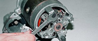
At the rear end of the starter you can see its power terminals and copper parts:
The starter itself is manufactured in China under license and under the control of a Russian company, it is compact and its weight is small, about 3 kg:
The working part of the starter is somewhat smaller than the similar part of a standard starter; the gear feed mechanism and the starter fastening itself are, of course, standard:
View of the starter itself from the other side:
I would like to note the fact that the 13 wrench nut on the upper terminal at the top right in the photo (the lower nut on the copper bolt) was loosely tightened, and we managed to tighten it well. When tightening this nut, the force may cause the black cage of the round insulator of the solenoid relay to turn slightly, from where the copper bolts come out. To prevent this from happening, you need to tighten the nut carefully, without excessive lateral forces, and hold the cage itself with your hands. If the clip still turns a little, you need to carefully return it to its place with your hands and force. In the working position, this clip is fixed with an internal lock, and you can feel this fixation with your hand. In the following photo you can evaluate the comparative dimensions of the new and old standard Zhiguli starter:
The difference, as they say, is visible to the naked eye. After installing the new starter, the car's engine was started. To be honest, I was delighted when the starter was working. The speed of the crankshaft at startup is such that it seems that the spark plugs have been pulled out of the engine, and cylinder compression has ceased to interfere with the operation of the starter. The startup sound has also changed dramatically. I also liked the fact that when the starter is turned on, the voltage drop in the on-board electrical network is relatively small. So far, the operation of this starter on the car brings true satisfaction. All that remains is to wait for the winter cold and check the confidence of starting the engine in the cold. I think such a starter will be able to do it.
This is interesting: How to disassemble a spark plug
Mounting block connection diagram
P1 — relay for turning on the heated rear window; P2 - relay for turning on the headlight cleaners and washer; P3 - relay for turning on sound signals; P4 - relay for switching on the electric motor of the engine cooling system fan; P5 - headlight high beam relay; P6 - low beam headlight relay; A - the order of conditional numbering of plugs in the mounting block blocks. The outer number with the letter “Ш” in the plug designation is the block number, and the inner number is the conventional number of the plug.
Types of starters
There are two main types of starters, which differ in design and efficiency:
- Gearless , also simple or classic. This is the first design in which the motor armature and bendix are placed on the same shaft;
- Gearbox . It differs from the classic one in that a gearbox with a planetary gear is installed on the armature shaft, which drives the bendix.
The classic unit has certain disadvantages, which at one time forced engineers to reconsider its design. The most important of them is low maximum power. As car engines grew in size, so did the need for more power to run them. To obtain it, it would be necessary to increase the size of the starter, and therefore its weight and cost.
Schemes of individual blocks of the seven
Power supply system
Power plant starting system
1 - starter; 2 - relay; 3 — ignition switch; 4 - battery
Ignition system
1 - generator; 2 — ignition switch; 3 - distributor; 4 - breaker; 5 — candles; 6 - coil; 7 - battery
Contactless ignition system
External and internal lighting
Windshield wipers and washers
1 — electric motors of the windshield wiper; 2 — washer motor; 3 — mounting block; 4 — ignition switch; 5 - washer switch
Cooling Fan
1 — fan electric motor; 2 - sensor; 3 — mounting block; 4 - ignition relay; 5 - ignition switch.
Starter repair
As you know, VAZ-2107 cars are equipped with both injectors and carburetors. In this regard, the sequence of actions and the repair work on the starter itself may differ slightly from each other. However, no matter what your car is, it is quite possible to solve this problem yourself.
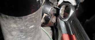
First of all, it is necessary to dismantle the starter. To do this, the car is installed above the inspection hole or raised on a lift. But first you should disconnect the negative terminal from the battery. Next, the procedure depends on what is installed on your car: carburetor or injector.
Wires for connecting electrical appliances
| Connection type | Section, mm 2 | Insulation color |
| Negative terminal of the battery - vehicle ground (body, engine) | 16 | Black |
| Starter positive terminal - battery | 16 | Red |
| Positive contact of the generator - plus battery | 6 | Black |
| Generator - black connector | 6 | Black |
| Terminal on the generator “30” – white MB block | 4 | Pink |
| Starter connector “50” – starter relay | 4 | Red |
| Starter Start Relay - Black Connector | 4 | Brown |
| Ignition switch relay - black connector | 4 | Blue |
| Ignition switch output “50” – blue connector | 4 | Red |
| Ignition switch connector “30” – green connector | 4 | Pink |
| Right headlight plug - ground | 2,5 | Black |
| Left headlight plug - blue connector | 2,5 | Green, gray |
| Generator output “15” – yellow connector | 2,5 | Orange |
| Right headlight connector - ground | 2,5 | Black |
| Left headlight connector - white connector | 2,5 | Green |
| Radiator fan - ground | 2,5 | Black |
| Radiator Fan - Red Connector | 2,5 | Blue |
| Ignition switch output “30/1” – ignition switch relay | 2,5 | Brown |
| Ignition switch contact “15” – single-pin connector | 2,5 | Blue |
| Right headlight - black connector | 2,5 | Grey |
| Ignition switch connector “INT” – black connector | 2,5 | Black |
| Six-pin block of the steering column switch - “ground” | 2,5 | Black |
| Two-pin block of the steering column switch - glove box illumination lamp | 1,5 | Black |
| Glove compartment light - cigarette lighter | 1,5 | Black |
| Cigarette lighter - blue block connector | 1,5 | Blue, red |
| Rear window defroster - white connector | 1,5 | Grey |
troubleshooting
In order to correctly determine where to start, you should think about what could be the reason that the starter does not work:
- If, after you turn the key in the ignition, the engine stubbornly refuses to start, you should check the light bulbs located on the instrument panel. If they burn weakly or go out completely, most likely the reason lies in a non-functioning battery. Or it may simply be discharged. We pick up a tester and check the battery capacity and voltage;
- if the battery is fully operational, you need to check what position the speed switch is in and move it to the “P” position;
- The next thing to figure out is whether the power from the ignition switch is getting directly to the starter.
There are two ways to do the last step.
Method 1. A wire made of copper with a cross-section of 2.5 mm is inserted into the open connector. One end goes to the starter and the other to the battery terminal. Thanks to this method, it is possible to simulate ignition.
Method 2: This verification method will require two people. One of them will turn the key in the ignition switch, while the second will touch the tip of the wire that comes from the unloading relay with a control probe. If the warning light comes on during this procedure, this indicates that there are no problems in the ignition switch, as well as in the relay.
Car wiring diagram
1 – radiator fan drive motor; 2 – relay and fuse block (mounting block); idle speed sensor; 4 – engine control unit; 5 – potentiometer; 6 – set of spark plugs; 7 – ignition control unit; 8 – electronic crankshaft sensor; 9 – electric fuel pump; 10 – tachometer 2107; 11 – lamp for monitoring the health of electronic systems; 12 – ignition system control relay; 13 – speed sensor; 14 – diagnostic connector; 15 – set of injectors; 16 – adsorber solenoid valve; 17, 18, 19 – fuse block protecting the injection system circuits; 21 – electronic fuel pump control relay; 22 – electronic relay for controlling the intake pipe heating system; 23 – intake pipe heating system; 24 – fuse protecting the heater circuit; 25 – electronic oxygen level sensor; 26 – cooling system temperature control sensor; 27 – electronic air damper sensor; 28 – air temperature sensor; 29 – pressure control sensor.
Fuse and relay diagram 2107
On newer “sevens” a block with 17 fuses and 6 relays is installed. VAZ 2107 fuses on the “new” unit protect the following electrical circuits and devices:
- Reversing lamps, heater fan, rear window defroster warning lamp and relay, rear wiper motor and rear washer pump.
- Electric motor for front wipers.
- Reserve socket.
- Reserve socket.
- Power supply for heated rear window.
- Clock, cigarette lighter, power socket “carrying”.
- Signal and radiator fan.
- Turn signal lamps in emergency mode.
- “Fog lights” and a relay that regulates the voltage of the on-board network.
- Instrument panel lamps.
- Brake light bulbs.
- Right high beam headlight.
- Left high beam headlight, high beam warning lamp.
- Side lights (rear right, front left), license plate and engine compartment lighting.
- Side lights (rear left, front right), glove compartment and cigarette lighter lamps.
- Low beam (right lamp).
- Low beam (left lamp).
The block relays perform the following functions:
- Heated rear window relay.
- Headlight cleaner and washer relay.
- Signal relay.
- Cooling system electric fan relay.
- High beam relay.
- Low beam relay.
The fuse block of the VAZ 2107 (injector) is no different from the block on the carburetor “seven”. Injection models are simply equipped with an additional relay and fuse box installed in the cabin under the glove compartment. The block includes three relays - the “main” relay, the fuel pump relay and the fan relay.
Diagnosis of faults and disassembly of the mechanism
The starter, removed from the engine compartment, must be cleaned of dirt and traces of technical fluids. The procedure for disassembling the mechanism is as follows:
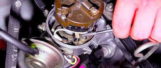
- We remove the solenoid relay from the starter housing and, having unscrewed the tightening screws, disassemble it into its component parts. During the inspection, special attention is paid to brass contact groups, the burning of which can lead to failure of the mechanism.
- We remove the cover of the device and check the condition of the brush assembly. Significant wear on the tracks and wear of carbon parts is a common cause of starter failure.
- The integrity of the rotor winding is checked using a multimeter set to resistance measurement mode.
- The overrunning clutch is checked by hand; a working device allows only one-way rotation.
After establishing the cause of the failure of the electric starter, you should take care of purchasing the necessary spare parts.
Modifications of the VAZ-2107 car
VAZ-2107 . Basic version of the sedan, with an 8-valve carburetor VAZ-2103 engine, 1.5 liters.
VAZ-2107-20 . The same VAZ-2107, but with a 1.5-liter VAZ-2104 injection engine that meets the Euro-2 environmental standard.
VAZ-2107-71 . The car for the Chinese market was equipped with a VAZ-21034 engine, with a volume of 1.4 liters and a power of 66 horsepower, specially tuned for A-76 gasoline. The pistons were taken from a VAZ-2108.
VAZ-21070 . Modification of a car with an 8-valve, carburetor VAZ-2103 engine, volume 1.5 liters.
VAZ-21072 . Modification with an 8-valve carburetor VAZ-2105 engine, volume 1.3 liters.
VAZ-21073 . An export modification for the European market, which was equipped with a 1.7-liter injection engine with a capacity of 84 horsepower. The engine of this car had a catalytic converter that satisfied environmental protection requirements.
VAZ-21074 . Modification with an 8-valve, carburetor VAZ-2106 engine, volume 1.6 liters.
VAZ-21074-20 . Modification with a 1.6-liter VAZ-21067-10 injection engine, which complies with the Euro-2 environmental standard
VAZ-21074-30 . Like the previous model, but with a VAZ-21067-20 engine, which meets the Euro-3 environmental standard
VAZ-210740 . Modification produced in 2010, equipped with a VAZ-21067 injection engine with a catalyst. Engine capacity is 1.6 liters, power is 72.7 horsepower.
VAZ-21076 . Export modification with a VAZ-2103 carburetor engine.
VAZ-21077 . Export modification with right-hand drive for the UK market. The car was equipped with a VAZ-2105 carburetor engine with a volume of 1.3 liters.
VAZ-21078 . Another export modification for the UK, but with a 1.6-liter VAZ-2106 carburetor engine
VAZ-121079 . The modification, developed specifically for the needs of the Ministry of Internal Affairs and the KGB, was equipped with a powerful VAZ-413 rotary piston engine with a volume of 1.3 liters and a power of 140 horsepower.
VAZ-2107 ZNG . The car is equipped with an 8-valve, fuel-injected VAZ-21213 engine with a volume of 1.7 liters.
How does the starter start the engine?
Let's take a closer look at the principle of operation of the starter. After closing the contacts, the current flows to the winding of the traction relay. At this time, the anchor moves and extends the bendix. The gear of the latter is connected to the flywheel ring. When the armature reaches its final position, the contacts close, allowing current to flow to the starter motor winding. The device begins to rotate and the car starts.
The Bendix returns to its original position as soon as the flywheel begins to rotate at a higher speed than the starter shaft. And the supply of electrical energy to the device stops when the key returns to the first position. A gear starter is also installed on the VAZ 2107, in this case the current flow pattern is slightly different; it reaches the armature through a gear drive. Thanks to this, power is significantly increased. This is not the only difference that the gear mechanism has, but we won’t talk about that now.