01/26/2022 8,014 Video and media devices
Author: Ivan Baranov
Recently, more and more of our compatriots are paying attention to the arrangement of speaker systems in their cars. Today, there are many solutions to ensure high-quality sound from car radios. From this material you can find out what the ISO connector of the radio is and what its pinout is.
[Hide]
Standards 1DIN and 2DIN
The differences between them are the height of the radios. The number 2 in the designation of the 2DIN standard indicates that the height of a double-DIN receiver is 2 times greater than a device made according to the 1DIN standard. The latest radios are now the most popular and widespread. Installation of double-din radios is not possible in every car, since an appropriate seat must be provided on the front panel.
All car radios are divided into two types: with a proprietary connector, most often made in the form of a plug, and located on the rear wall, and with a universal ISO connector. In the first case, you should purchase a proprietary connector for the radio, the pinout of which matches the desired model. If the machine has an ISO socket, then the other end of the proprietary cable should also have an ISO plug. In the second case, the radio is connected directly to the ISO socket located in the car.
When replacing the radio with another one, you should look at the back wall and determine which block is located there. After this, you can decide whether to purchase a proprietary plug or you can connect the device to the machine through an already installed ISO socket. The pinout of the car radio connector is carried out according to the ISO 10487 standard.
Classification of car radios by size
Car head units on the market differ in functionality, sound parameters and installation dimensions.
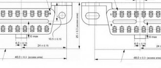
Developed by German manufacturers, the standard for car head units DIN 75490 was adopted in 1984 as international ISO 7736. It defined the standard mounting hole size for a car radio (1-DIN) as 180 x 50 mm. This size is the 1 DIN size. DIN stands for Deutsches Institut fur Normung - German Institute for Standardization. The abbreviation DIN stands for German standard.
Igor Syroedov
https://steer.ru/node/29859
Unification of installation dimensions expands the possibilities of using various radios in cars of different manufacturers and models. Currently, all radios are produced in accordance with the requirements of the international standard ISO 7736, but motorists prefer to refer to the similar international German standard DIN 75490.
All radios are produced in accordance with the requirements of the international standard ISO 7736, similar to the German DIN 75490
Usually there is enough free space behind the car console, so the standard regulates only the width and height of the radio, without limiting the depth. There are two formats: 1 DIN (178 x 50 mm) and 2 DIN (178 x 100 mm).
There are two radio size formats: 1 DIN (178 x 50 mm) and 2 DIN (178 x 100 mm)
In practice, the seat may be slightly wider and higher. In this case, to mask the cracks, decorative transition frames are used, which can be found on sale for almost any car model.
Decorative transition frames are used to mask the gaps between the radio and the seat
Adapter frames are also used when it is necessary to install a 1 DIN radio in a 2 DIN slot. The reverse procedure - installing a 100 mm high radio in a 50 mm opening - is impossible without significant modification of the console.
Video: choosing a radio by size
ISO pinout
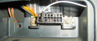
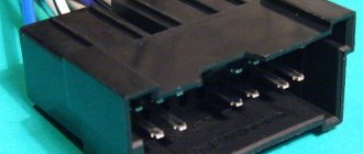
Many new radios increasingly use a Euro connector. It is a rectangular sixteen-pin plug consisting of one or two equal parts. An ISO plug is installed on the car, allowing you to connect any car radio that has the appropriate connector. The ISO pinout does not depend on the radio model equipped with such a connector.
Upper power connector A
It is used to supply current from the vehicle's on-board network, as well as to remove power from an active antenna or amplifier, to mute the sound and supply a backlight control signal. According to the standard, wires are marked by color:
- yellow - direct connection to the vehicle’s battery; it also supplies power to the receiver’s RAM, which provides storage of settings specified by the user;
- red - it supplies the main power;
- black is ground, the negative pole connected to the GU body;
- blue with a white stripe - when the car player is turned on, 12 V is supplied to the active antenna amplifier or the remote control controller of the car audio power amplifier;
- orange - a signal is sent to it from the vehicle’s side light switch to control the backlighting of the keys and display;
- brown - used to mute the sound, for example, while talking on the phone.
It is worth considering that two power supply systems are used. In the first case, the yellow and red wires on the pinout are connected together. The power supply to the radio does not depend on the position of the ignition key.
If you leave the car player on without a protection timer, the car battery may quickly drain.
The second system involves connecting the red wire through the ignition switch, and the yellow wire directly to the on-board network. Thanks to this, the power supply to the radio is connected to the position of the key. When the ignition is off, you can remove or insert the CD. It also keeps the audio system's built-in clock running and saves settings such as sound settings and radio channels.
The pinout of the ISO connector of the radio, intended for power supply, is carried out as follows. Pins 1, 2 and 3 are reserved and are used by some head units to enable additional functions. Pin 4 is connected to the yellow wire, and pin 5 is connected to the blue/white wire. An orange wire is connected to pin 6. Pin 7 is connected to the red wire, and pin 8 is connected to the black wire. This connector is often painted brown.
Bottom speaker connector B
It is used to supply amplified sound from the car player to the speakers. The wires through which alternating current directly flows from the microcircuit are solidly colored, and the wires connected to ground have black stripes. Color marking is carried out as follows:
- the white wire connects to the left front speaker;
- the gray wire connects to the right front speaker;
- the green wire connects to the left rear speaker;
- The purple wire connects to the right rear speaker.
Is everything working correctly?
- After connecting all the wires, do not put the device back into the panel. Check the power first. Turn the radio on and off. Set a couple of settings and reboot the device. If they are not lost, proceed to the next step.
- Turn the volume up to 75% and listen to the sound from the speakers. It should be smooth without strong wheezing sounds or other noises. If possible, listen to each side and each speaker separately. It happens that the phases of the wires are confused and the speakers play in antiphase. You can hear it right away.
- Check the radio. Signal reception quality.
If everything is in order, put the car radio back in place and listen to music. Ready.
Pinout diagrams for radio tape recorders from popular manufacturers
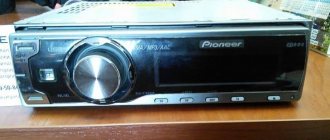
Wiring of linear outputs on a standard radio can be done using two RCA connectors. This option is the most common, since power amplifiers have the same sockets. The pinout of connectors for Pioneer car radios contains from 10 to 20 contacts. Their purpose depends on the model of the multimedia device. For example, in the KEH series, the first pin is the antenna control, the second pin is the voltage from the ignition switch, etc. The speakers are connected to pins 3, 4, 5, 6, 8, 9, 10 and 11.
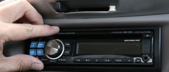
Many motorists are faced with the need to replace the head unit. The process requires a radio pinout and a guide for connecting the audio system.
Pinout of a standard Euro connector
The Euro connector is a standard plug for many modern devices. An ISO plug is installed on the machine, thanks to which it becomes possible to connect any model of radio with the appropriate connector.
Standards 1DIN and 2DIN
The difference between the standards lies in the size of the devices: a 2-din device is 2 times higher than a 1-din device.
The most common are 1-DIN radios, because Installation of higher devices due to the lack of a seat of appropriate size on the front panel of the car is not possible in every car.
There are 2 types of radio tape recorders:
- With proprietary connector. You need to choose a product whose pinout matches the desired car.
- With universal connector. The device connects directly to the ISO socket provided in the car.
Pinout is carried out according to ISO 10487 standard.
Upper power connector A
The connector serves as a connector between sources and consumers of electricity from the on-board network.
Plugs 1, 2, 3, 6 are rarely used in radio circuits of the lower and middle price segments. The elements are used when connecting additional options in higher quality player models. Wire colors may vary.
You should understand the purpose of the contacts:
- ANT. Used with a retractable antenna.
- Remote. Designed for connecting external amplifiers. Thanks to it, you can increase the number of mounted speakers, which is necessary in the interiors of large cars.
- Illumination. Adjusts the brightness of the player screen (the higher the driving speed, the less intense the backlight, so as not to distract the driver).
- Mute. Adjusts the sound of the device.
- A4. Turns the audio system on and off.
This connection scheme allows you to protect the battery from discharge, because turning on the system is possible only when you turn the ignition key, while the acoustic cascades consume electricity even when turned off.
The pinout of the ISO connector of the radio (European) looks like this:
- Connector A5 (blue) is for the antenna. If the permissible current value (300 µA) is exceeded, both the amplifier stages and the entire head unit may break.
- Wire A7 (red) is intended to power the head unit. When it is disabled, the settings are returned to factory settings. Voltage - 12 V.
- Cable A8 (black). Responsible for connecting the speaker system to the car.
To protect the audio system, the wires must be equipped with a fusible link. If interruptions occur in the operation of the player, you should place a capacitor between connectors A7 and A8, which will act as a filter, smoothing out fluctuations in the electrical circuit.
Bottom speaker connector B
The speakers are connected through it as follows:
- Rear right + (purple).
- Rear right - (black and purple).
- Front right + (gray).
- Front left - (black and gray).
- Front left + (white).
- Front left - (black and white).
- Rear left + (green).
- Rear left - (black and green).
Most devices are designed for 4 channels; 8 wires are used for this (2 pieces per speaker).
The sound quality of the system depends on the “flattening”. If you mix up the connectors, the device will not fail, but the radio will not work correctly.
Audio system elements should be connected with cables with a cross-section of 1.5 mm or more. Thicker wires are used on power lines.
How to make your own exit
The vehicle owner can independently install or replace the plug:
- Purchase an ISO connector from a radio store that matches the plug on the head unit housing. If a bundle of wires is installed on the radio, then purchase a block suitable for switching with the mating part on the car wiring.
- Using a test device, determine the cables responsible for supplying voltage to the radio power supply. The wires have an increased cross-section and are protected with red and black insulation. When installing the plug on the radio, you should briefly apply 12 V voltage to the found cables, which will make sure that the device is working.
- Separate the speaker wires, determining the direction of wiring from the electrical diagram of the machine. When connecting speakers, it is prohibited to connect the negative wire to a common line or connect it to the car body. Devices connected in this way operate with overload and do not provide high-quality sound transmission.
- Among the remaining wires, find the cable responsible for the operation of the antenna.
- Distribute the cables among the plug contacts according to their intended purpose. The new connector has special rods to which the bare ends of the wires are attached. A special crimping tool is used for connection, ensuring reliable contact.
- Connect the wiring harnesses and check the functionality of the head unit and acoustics in various playback modes.
It is possible to purchase a plug with already installed wires, removed from a wrecked car or a faulty radio. After determining the purpose, the cables are connected using crimp tubes. The joint is protected with insulating tape or heat shrink tubing. Excess cable length is collected into coils, which are then secured with plastic clamps. The installed harness must not have contact with the rear cover of the radio, which is used as a radiator for the amplifier.
Performing the work requires a minimum of tools and skills. If the car owner is not confident in his own abilities, it is recommended to contact a service center that installs acoustic equipment.
ISO is used as the generally accepted European standard for connecting car radios. The pinout of the radio is carried out in accordance with it.
Pinouts for various brands of cars and radios
The wiring of the linear outputs on the standard radio depends on the make of the car and the head unit.
Before pinouting the connectors of the car radio, you must read the information presented on the cover of the device and in the instructions for it.
Toyota
For a standard plug: 1 - A+, 2 - GND, 3 - BAT+, 4 - backlight, 5 - antenna adjustment, 9-16 - speakers (RR+, RR-, RF+, RF-, LF+, LF-, LR+, LR -).
Universal connector for most models: 1 - ANT, 3 - linear output LR, 4 - GND linear outputs, 5 - linear output RR, 6 - CD in LCH, 7 - CD in GND, 8 - CD in RCH, 9 - CD reset , 10 — CD clock out, 11 — CD DSPL select, 12 — CD data out, 13 — CD clock in, 14 — CD data in, 16 — A+, 17 — GND, 18 — ANT GND, 22-27 and 29- 30 — speakers (LF-, LR+, RF-, RR+, LF+, LR-, RF+, RR-), 28 — CD mute, 31 — ANT CONT, 32 — CD ACC CONT, 33 — AMP CONT, 34 — B UP .
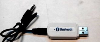
Adapters for different connectors
The elements are designed to connect the car radio to the car's electrical network using various plugs. Often, adapters are equipped with ISO connectors on one side, and on the other, a non-standard proprietary connector suitable for a particular car model.
Using such elements, you can mount speaker systems with Euro connectors instead of devices with original plugs, and there is no need to re-solder the conductors or any other intervention in the machine’s electrical network. On sale you can find products with 2 non-standard plugs.
Sometimes the car is not equipped with connectors, then you need to connect the plug suitable for the radio to the wires in the car. This is done both by twisting and soldering. A terminal block is also used for this purpose; additional insulation is not needed in this case. When twisting and soldering, you will have to use cambrics or heat-shrink tubing to ensure safe use of the device.
Adapters are used to connect:
The advantage of using the elements is that there is no interference with standard wiring: the user does not have to solder or cut wires.
On devices with the option of control from the steering wheel of the car, a button adapter is provided - another type of adapter. It is a special device with which you can replace the standard audio system with other equipment.
Power connection
Connecting the power supply is the stage at which most mistakes are made when connecting the radio.
To connect power to the radio, it is better to use a separate wiring to the battery, and the wires should have a cross-section of 2-4 sq. mm.
To obtain clean playback after installation, it is better to connect the black and yellow wires to the battery. Install an additional 10-20 A fuse on the yellow wire. The red wire is connected to the ignition circuit.
As a rule, the red and yellow wires are connected together, so the radio operates regardless of the ignition being turned off. But this option has a caveat - the radio will drain the battery, because will remain in sleep mode all the time after shutdown. To eliminate the possibility of the battery being discharged due to this nuance, a separate shutdown button is additionally placed on the red wire, thanks to which the power will turn off automatically when the car is parked for a long time.